Creating 3D Isometric view of various structural elements in AutoCAD
Q1
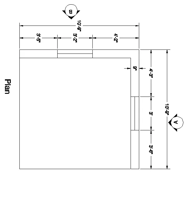
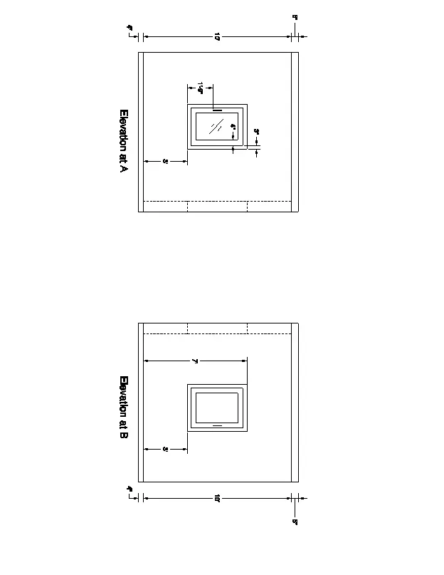
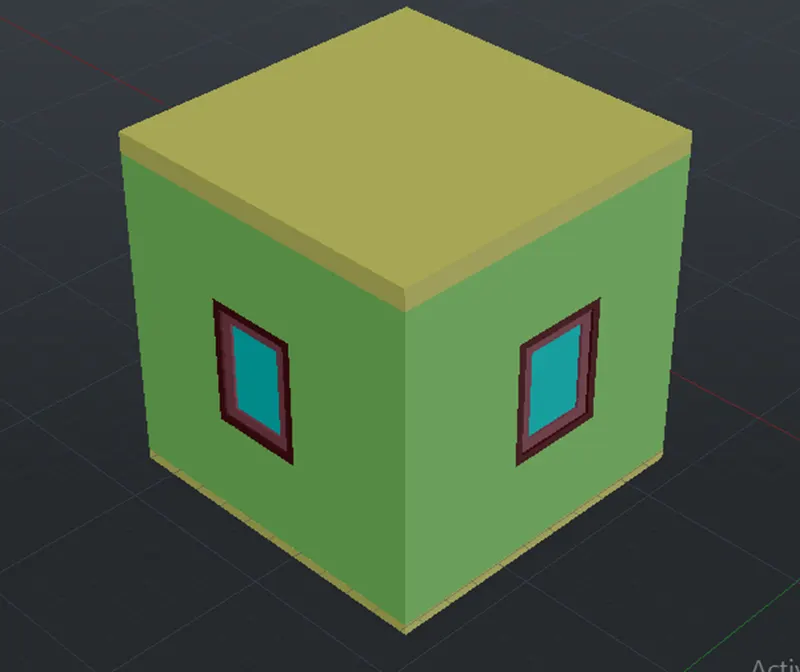
AIM : To create a 3D Isometric View of the building with plan and elevation given.
PROCEDURE :
STEP 1 :
Open AutoCAD application and go to settings and change the User interface to 3D modelling
STEP 2 :
Type unit or UN in the command box and press enter
Set type of unit as engineering and precision as 0'0"
In Insertion scale set unit as inches
STEP 3 :
Type dimension style manager or D in the command box and press enter
Modify primary units as engineering and precision as 0'0"
STEP 4 :
Set the view to top view and using the line command and offset command draw the plan as shown in figure and give the dimensions
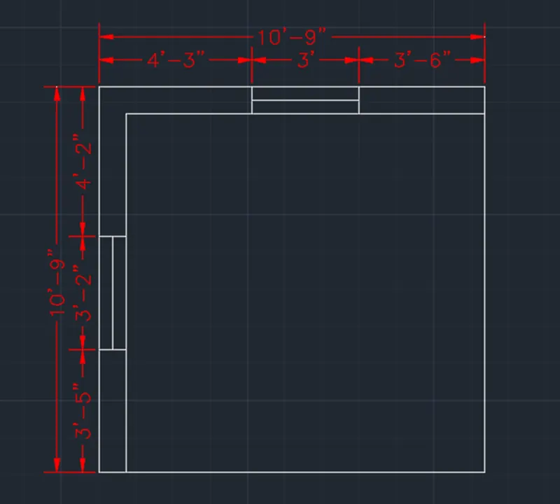
STEP 5 :
Create Boundaries and extrude the walls
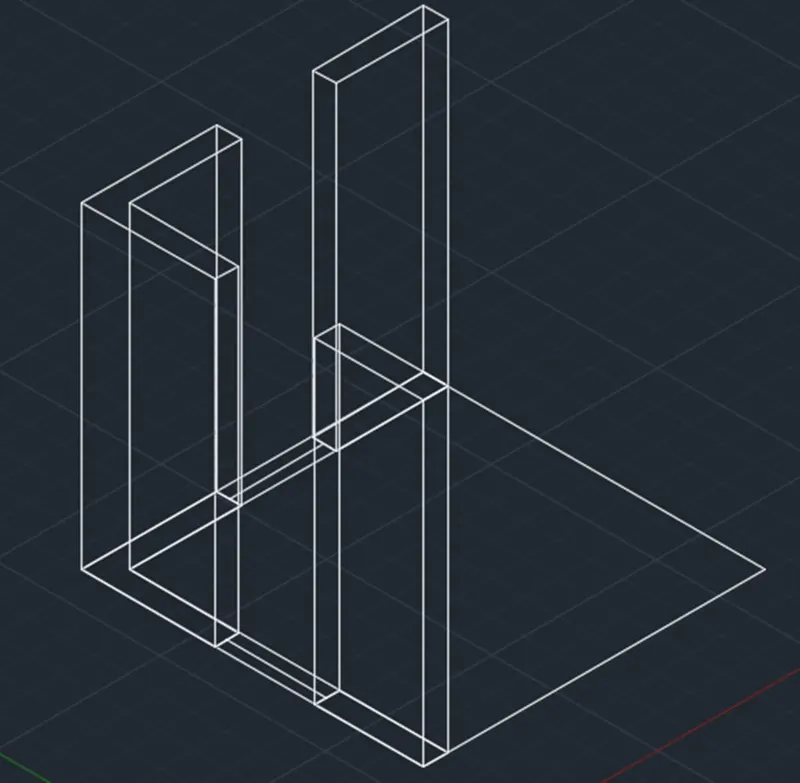
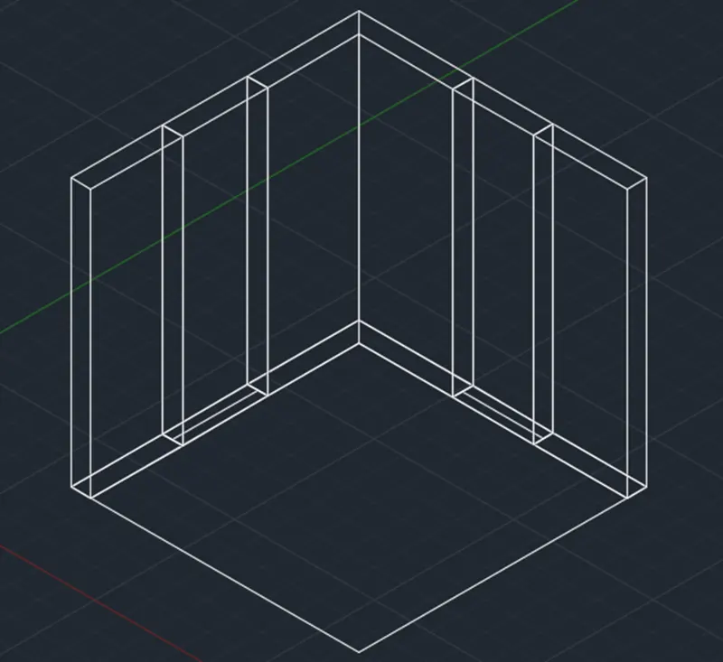
STEP 6 :
Make the walls single component using the union command
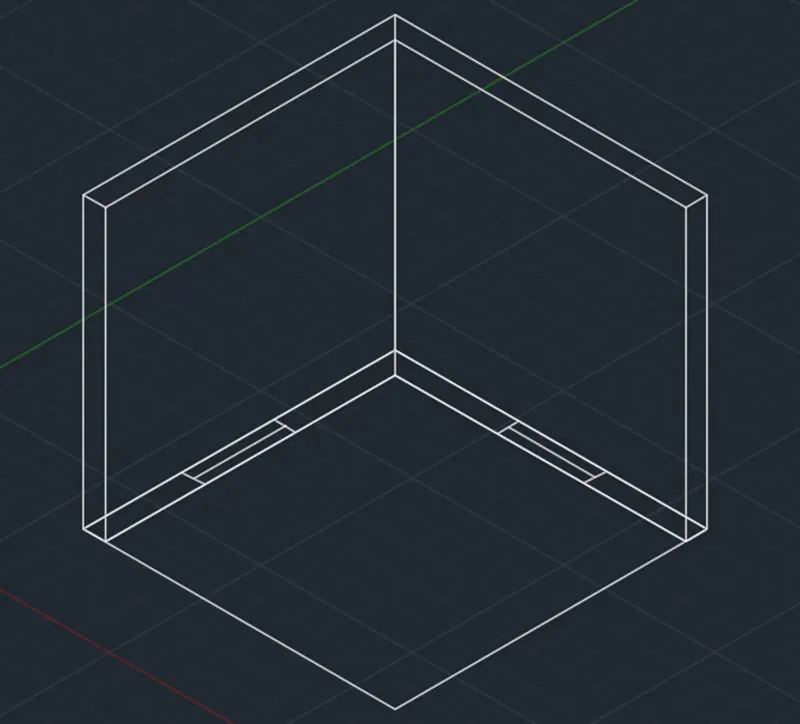
STEP 7 :
Using Subtract command make the window opening on the walls.
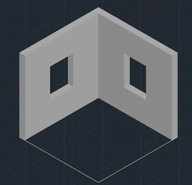
STEP 8 :
Draw rectangle on bootom and top of the wall region it and extrude it.
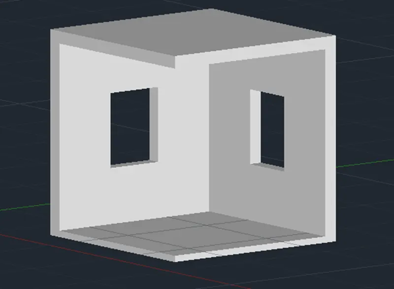
STEP 10 :
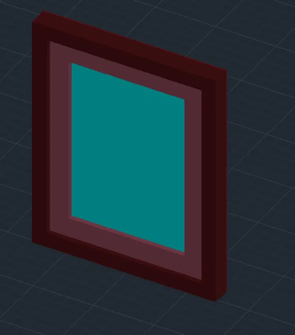
Draw window by using the line command region it and extrude it so that window of given size is drawn
STEP 11 :
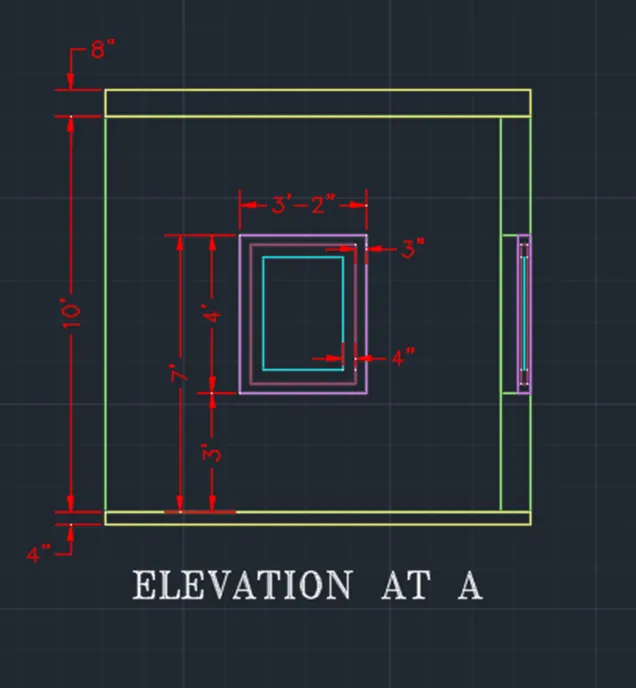
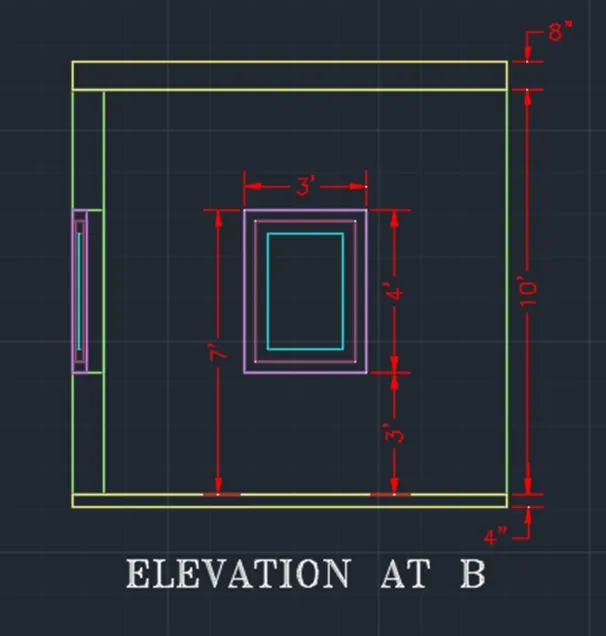
By changing the views elevation at A and elevation at B and give the dimensions
RESULT :
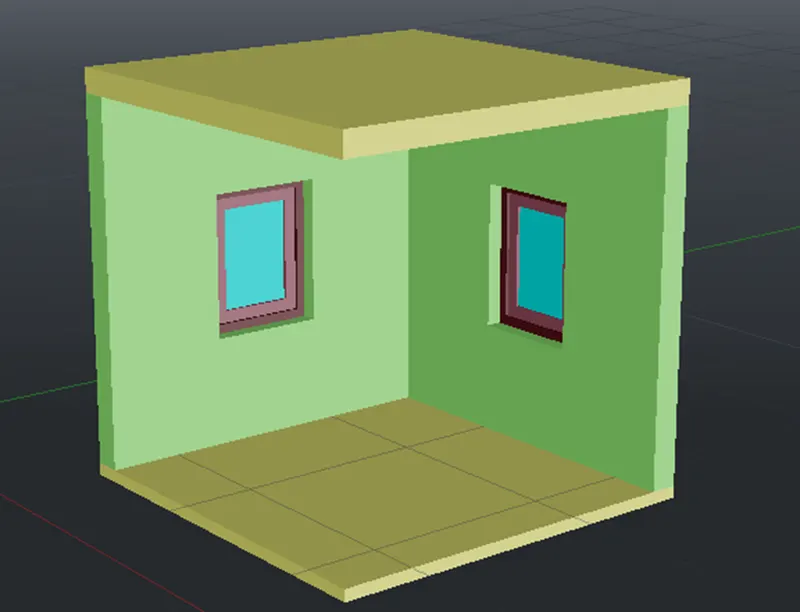
The given figure is drawn using necessary tools in AutoCAD 3D Modelling
Q2.
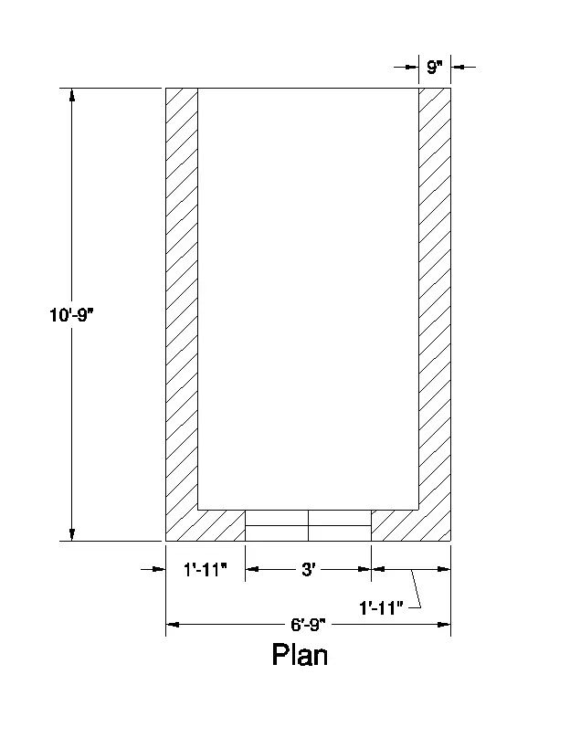
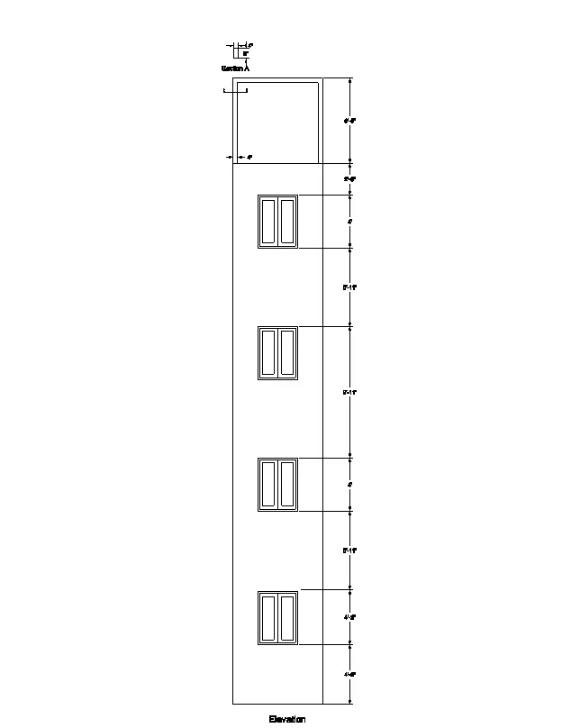
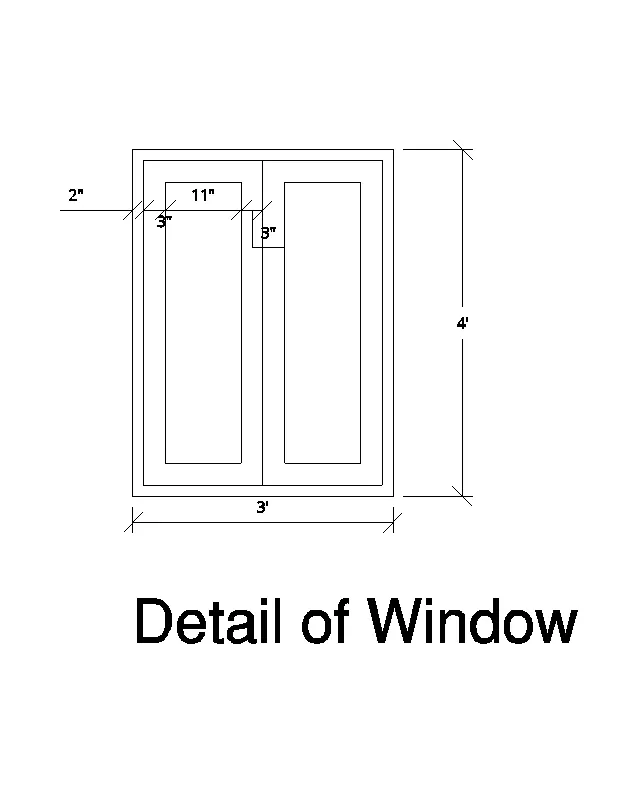
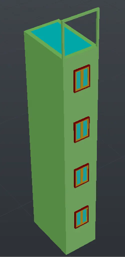
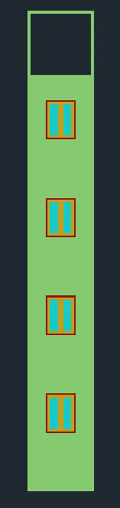
AIM : To create the 3D View of the Building Façade as given in the plan and elevation. Also, see the detail of the window.
PROCEDURE :
STEP 1 :
Open AutoCAD application and go to settings and change the User interface to 3D modelling
STEP 2 :
Type unit or UN in the command box and press enter
Set type of unit as engineering and precision as 0'0"
In Insertion scale set unit as inches
STEP 3 :
Type dimension style manager or D in the command box and press enter
Modify primary units as engineering and precision as 0'0"
STEP 4 :
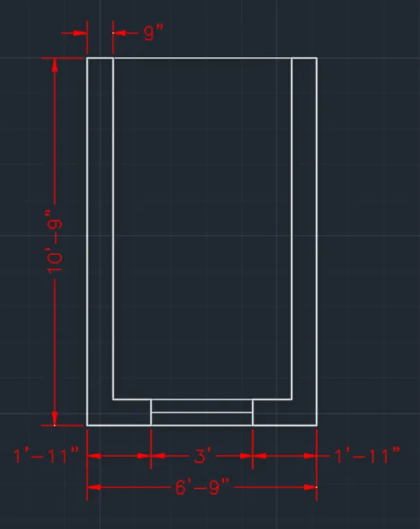
Set the view to top view and using the line command and offset command draw the plan as shown in figure and give the dimensions
STEP 5 :
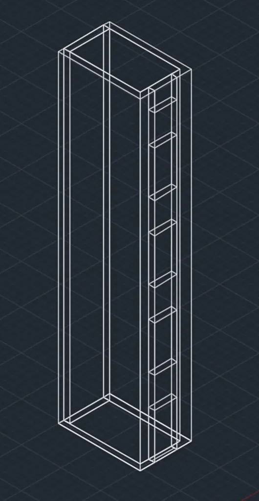
Create Boundaries and extrude the walls
Using Subtract command make the window opening on the walls.
STEP 6 :
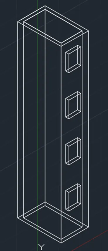
Make the walls single component using the union command
STEP 7 :
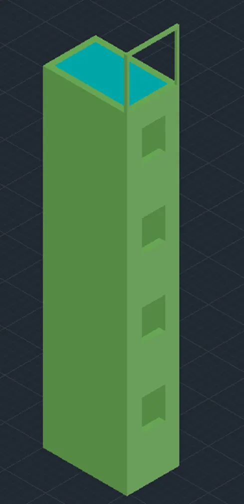
Using line command draw the upper portion of the building and region it and extrude it
STEP 8:
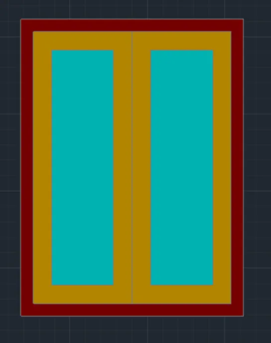
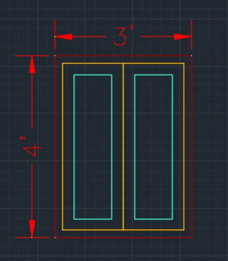
Draw window by using the line command region it and extrude it so that window of given size is drawn
RESULT :
The given figure is drawn using necessary tools in AutoCAD 3D Modelling
Q3.
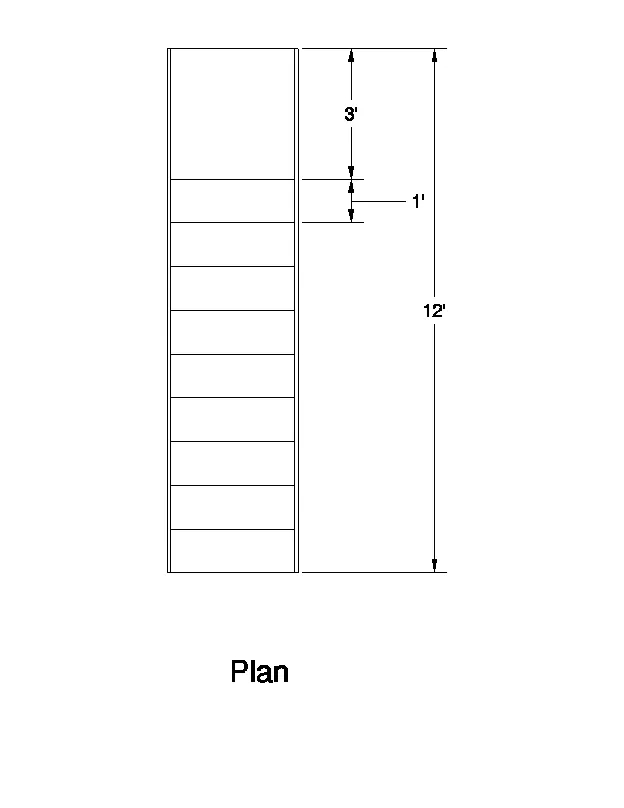
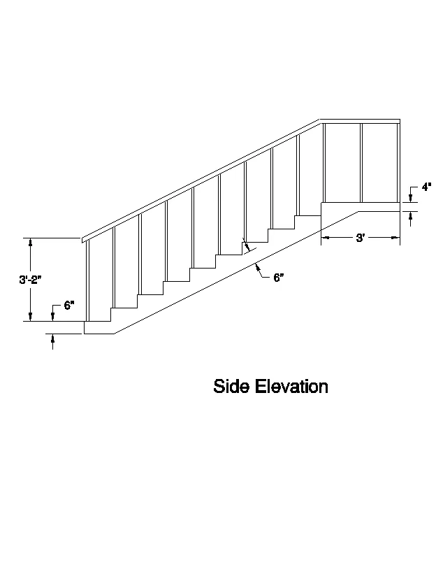
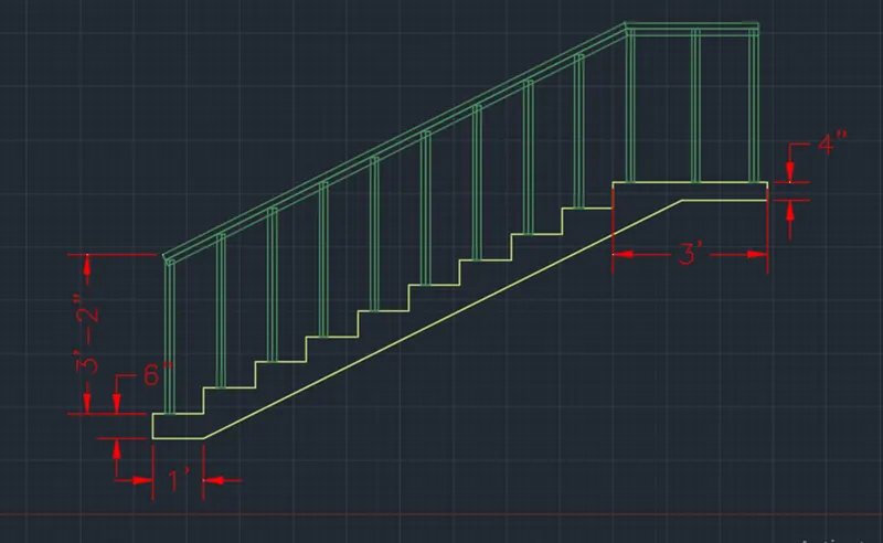
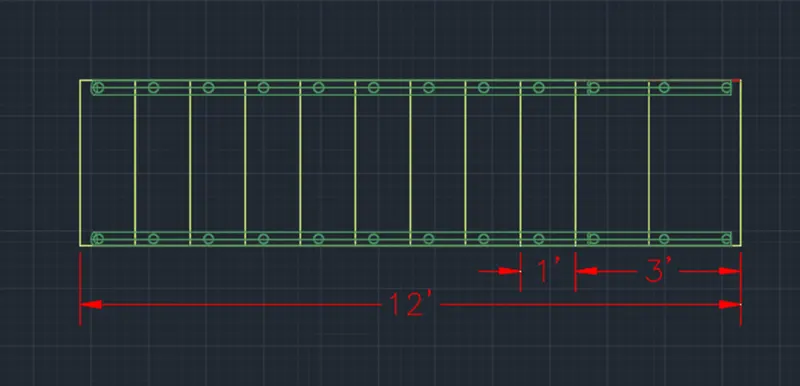
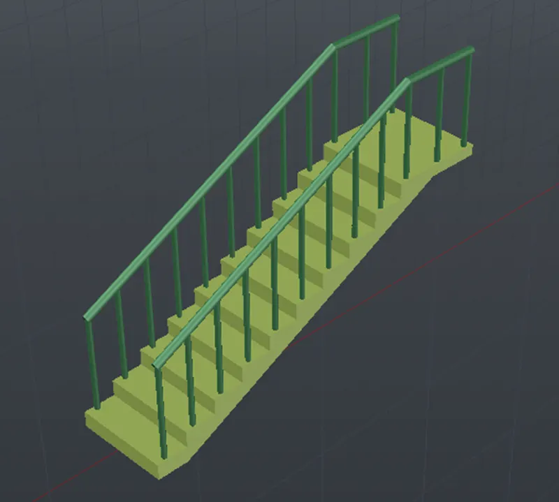
AIM : To create the ismoteric 3d view of a stair with railing as shown in the plan and elevation. Assume the size of the balustrades and the hand rails.
PROCEDURE :
STEP 1 :
Open AutoCAD application and go to settings and change the User interface to 3D modelling
STEP 2 :
Type unit or UN in the command box and press enter
Set type of unit as engineering and precision as 0'0"
In Insertion scale set unit as inches
STEP 3 :
Type dimension style manager or D in the command box and press enter
Modify primary units as engineering and precision as 0'0"
STEP 4 :
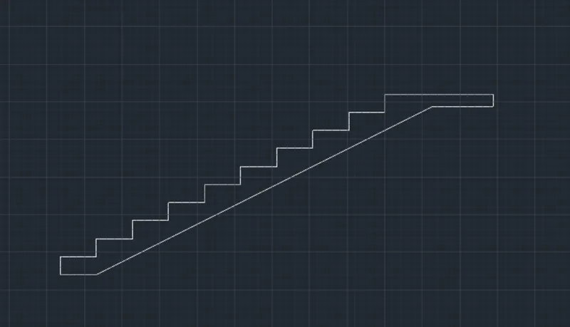
Set view to the front view and draw the staircase as shown in figure.
STEP 5 :
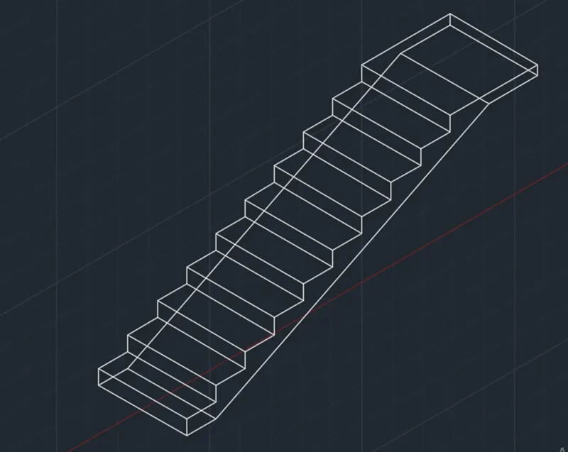
Make boundary of the staircase and extrude it for 3'
STEP 6 :
Create railings as per the given figure using circle command and sweep caommand
RESULT :
The given figure is drawn using necessary tools in AutoCAD 3D Modelling
Q4.
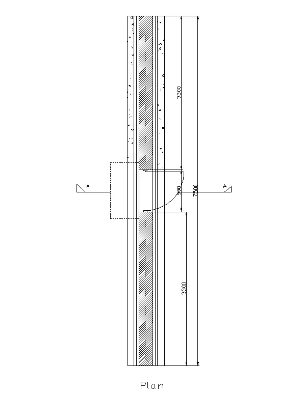
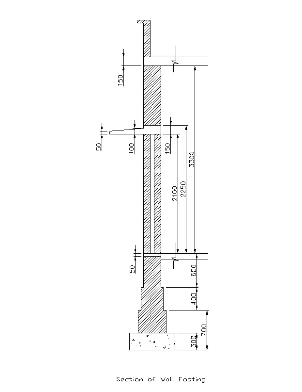
AIM : To create the 3D view of a Wall with spread footing . Create the Door opening only. Assume the size of the parpaet and the coping. See the plans and elevation for the details. Also, create a rendered view of the model with materials as of your choice.
PROCEDURE :
STEP 1 :
Open AutoCAD application and go to settings and change the User interface to 3D modelling
STEP 2 :
Type unit or UN in the command box and press enter
Set type of unit as decimal and precision as 0
In Insertion scale set unit as millimetre
STEP 3 :
Type dimension style manager or D in the command box and press enter
Modify primary units as millimetre and precision as 0
STEP 4 :
Set view to the front view and draw the spread footing as shown in figure.
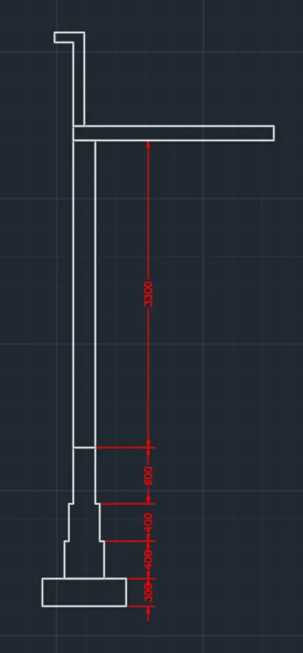
STEP 5 :
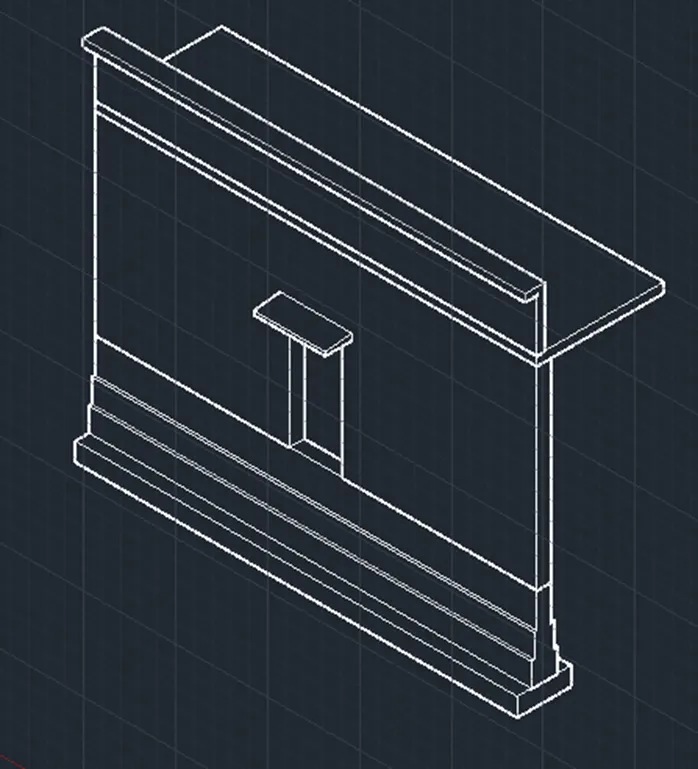
Make boundary of the spread footing and extrude it for 7500mm and create a opening of door and subtract it by usinf subtract command and create a chejja as shown in figure.
STEP 6 :
The given figure is drawn using necessary tools in AutoCAD 3D Modelling
STEP 7 :
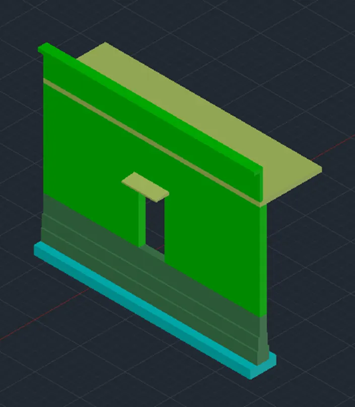
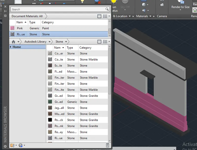
Give material to the spead footing drawn
STEP 8 :
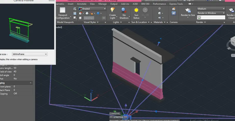
Set camera
STEP 9 :
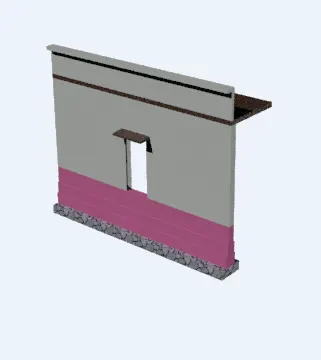
Render the image
RESULT :
The given figure is drawn using necessary tools in AutoCAD 3D Modelling