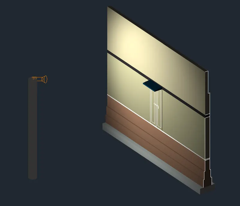
Creating 3D Isometric view of various structural elements in AutoCAD
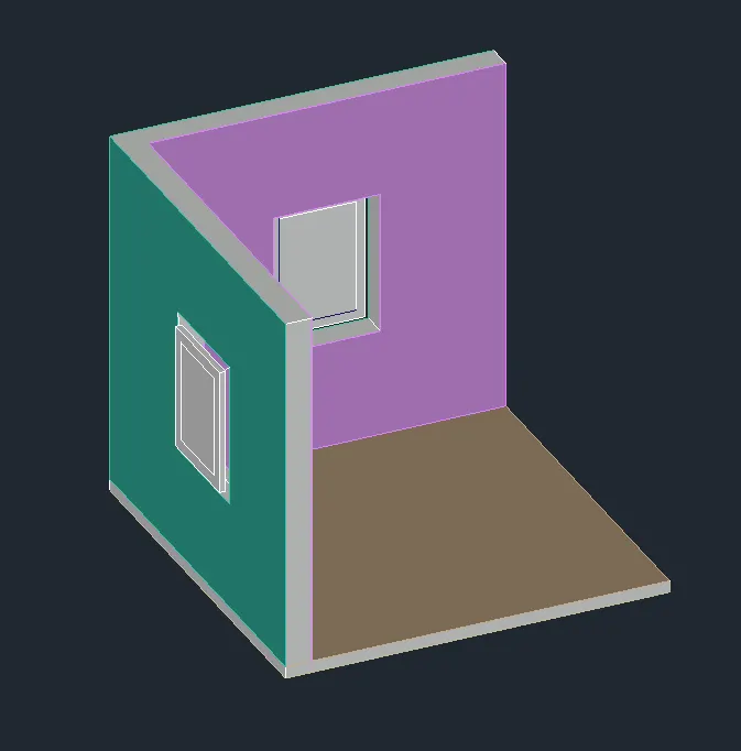
1. Creating a 3D-Elevation of a Room Plan with Pre-defined Dimensions and Two Window Designs on Two Faces of the room.
STEPWISE PROCEDURE:
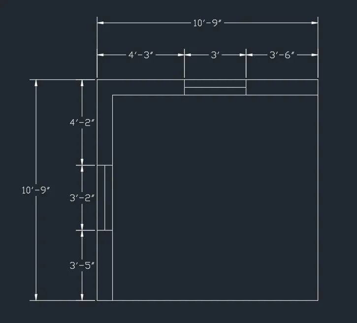
- Create the plan view of the room with a standard room size
- Use the "Rectangle" command and select the dimensions option to give them out to out length and breadth of the room as 10'-9".
- Explode the rectangle and use the offset command to draw a 9" thick wall on two sides of the room.
- Again use the rectangle command to place windows as per the geometry of the room.
- Use dimension to notify the room size in relation to the window placement.
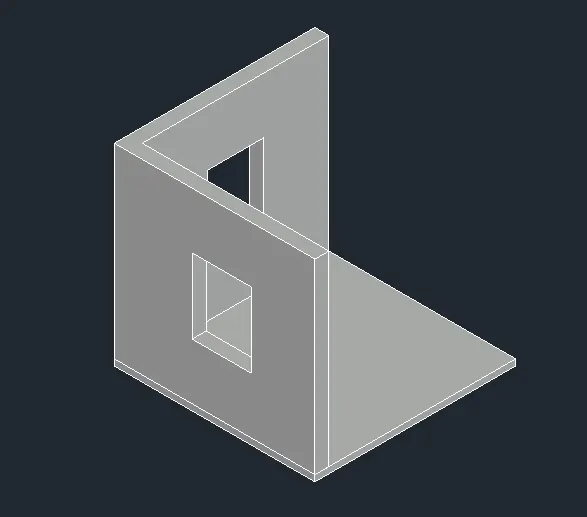
- Draw the overall 3d layout of the room
- Invoke the view cube and click on the home icon to go into the 3d workspace.
- Make a region out of the room by using the "region" command.
- Then, invoke the extrude command and select the region to extrude.
- Put the total floor height to extrude as 10'.
- Precisely place the windows into the 3d model by using move and copy commands.
- After locating the windows accurately on both walls, subtract the opening by using the subtract command.
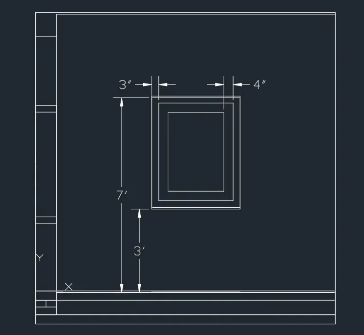
- Design the window frame for both walls.
- Enter "UCS" in the command line and set the UCS onto the window frame.
- Create a rectangular frame of the same size as that of the window.
- Give the internal offsets of 3 and four inches in steps to complete the design.
- Shade the model and color the faces
- Click on the Home icon to return to the 3d workspace.
- Enter UCS in the command line and select the world option to bring the UCS back to its original position.
- Use the "SOLIDEDIT" command then "F" then "L" to color the faces with different coloring options and finalize the model.
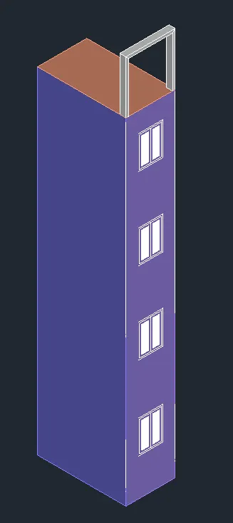
2. Creating the 3D Model of a Building Facade with Four Floors and Pre-defined Elevation height. Also, Design the Window Frame and Allot all the Windows Precisely into the 3D Facade.
STEPWISE PROCEDURE:
- Draw the Face Top view in the 2d-wireframe
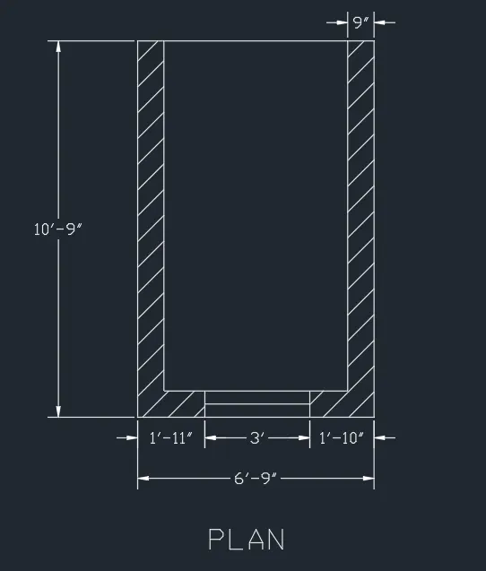
- Use the "RECTANGLE" command and use the dimensions option to input its length and breadth as 10'-9" and 6'-9" respectively.
- Explode the rectangle and create the 9 inch thick external walls on three visible sides of the facade.
- Draw a 3' wide window and locate it in the center of the front wall.
- Use the dimension tool to explain the plan with window placement.
- Design the Window elevation
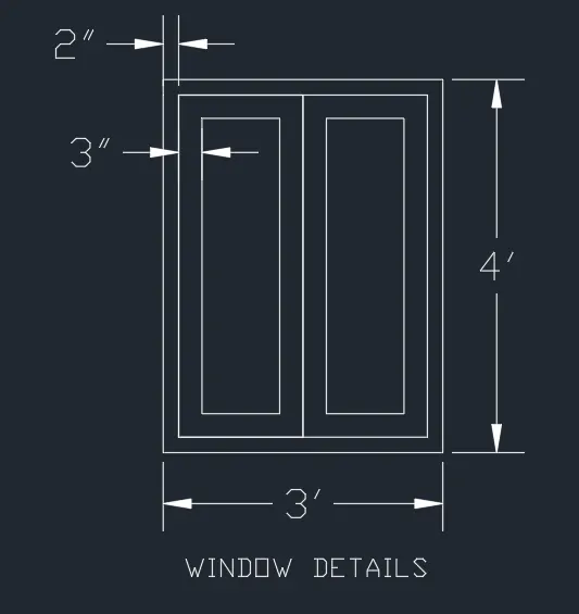
- Draw a rectangle of size 3' x 4'.
- Take an offset of 2 inches to create another rectangle within the rectangle.
- Divide the internal rectangle into two parts.
- Take an offset of 3 inches from the first division.
- Make the mirror image and create another rectangle inside the second division.
- Give dimensions to explain the design.
- Create the front elevation of the building facade
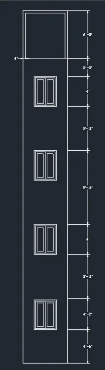
- Use the line command to create the elevation at ground level.
- Take the "OFFSET" command and start creating each floor level as per the building height.
- Use the "COPY" command to locate the previously designed window on each floor.
- Use rectangle command to create the Architectural ornament at the terrace.
- Design the 3d model of the facade
- Click on the home icon from the view cube to go into the 3d modeling workspace.
- Invoke the "ROTATE3D" command and select the 2d elevation.
- Specify the rotation axis and give the rotation angle of 90 degrees.
- Create the region from the rotated front elevation.
- Invoke the extrude command and give the suitable length to transform the model into the 3d facade.
- Use "SOLIDEDIT>F>>L" to color the facade and choose the appropriate coloring options.
- Use the hatch command to give a different look to the windows in 3d.
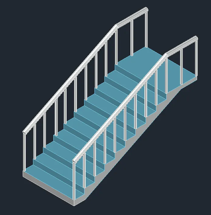
3. Creating a 3D Model of the Typical Staircase often Adopted in the R.C.C Buildings.
STEPWISE PROCEDURE:
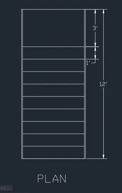
- Create the top view plan of the staircase
- Create a rectangle of the size 12' x 6'.
- Create a landing 3 feet long from the top face and locate the first riser.
- Use the tread of length 1' and create 10 treads using the offset command and complete the plan.
- Draw the side elevation for the staircase
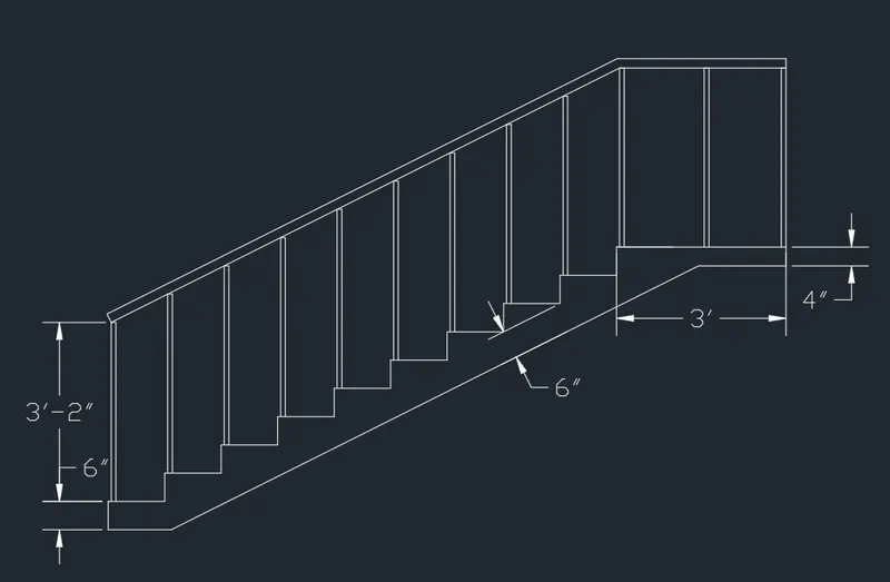
- Create the riser of 6" height and attach the same with the tread of 1' length.
- Make ten copies of the same riser and tread one above the other.
- Create the landing as specified in the plan.
- Create the waist slab of 6" thickness by using the line and offset commands.
- Create a railing of 3'-2" height and attach the same with the handrail.
- Create the 3d isometric view of the staircase
- Click on the HOME icon within the view cube to go into the 3d modeling workspace.
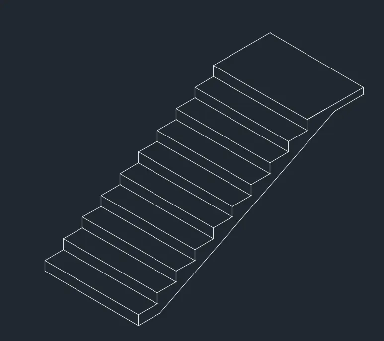
- Create a region from the staircase side elevation.
- Use the "ROTATE3D" command and specify the rotation axis along with the trad position.
- After rotating the staircase elevation and specify the extrusion length as 6' that is equal to the width of the landing.
- Create the 3d railing and color the staircase surface to make it look distinct
- Create a vertical line along the XZ plane of height 3'-2".
- Create a circle anywhere in the workspace of a suitable diameter.
- Use the sweep command and extract the circle into the circular handrail.
- Copy the same in the full flight and on the landing as well.
- Use the mirror command to create the same railing along the other side of the staircase.
- Now, use the solidedit tool to color the staircase surface to make it look distinct.
4. Creating the 3D Model of a Spread Footing Section with a Door Opening Midway along the Wall Section. Also generating the rendered view of the final drawing.
STEPWISE PROCEDURE:
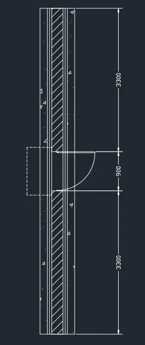
- Create the plan of spread footing section
- Use the line and offset commands to prepare the top view layout of the footing with the wall in the central portion.
- Create a door opening in the middle portion of the section within the wall thickness.
- Use the hatch command to differentiate between the footing and wall section.
- Give dimensions to explain the entire figure.
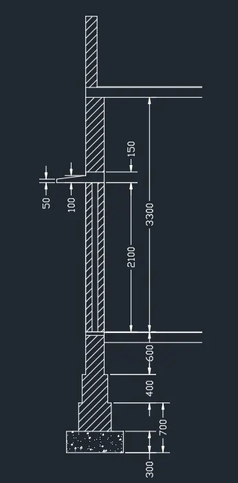
- Create the sectional elevation of the footing
- Use the industry-standard P.C.C bed size and footing dimensions to complete the substructure section.
- Create a floor of heigh 3300mm with the wall previously planned in the top view.
- Give 150mm slab thickness and design a parapet wall over it.
- Create the door opening section inside the wall.
- Place the roof over the door with 150mm concrete thickness.
- Hatch the section as per the masonry and concrete bed.
- Use dimensions to explain the section.
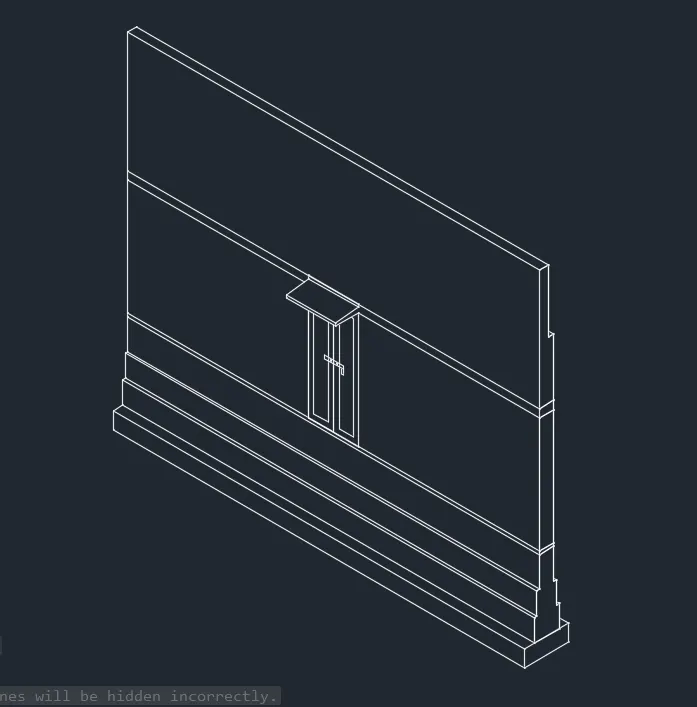
- Create the 3D isometric view of the footing section
- Click on the HOME icon located near the view cube to go into the 3d modeling workspace.
- Create the region out of the footing section.
- Use the rotate3d command and select the sectional view to rotate.
- Specify the rotation axis and give the rotation angle as 90.
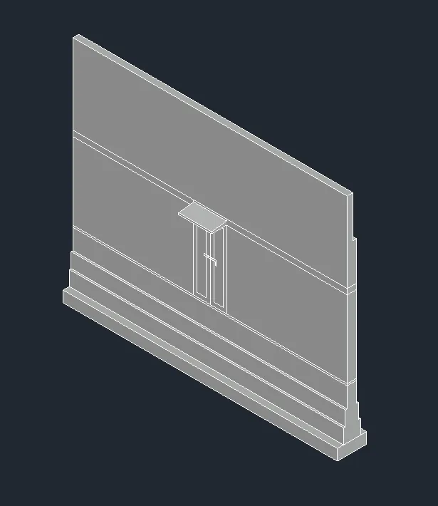
- Use the extrude command to extrude the section up to the length as mentioned in the plan.
- Type in hide in the command line and generate the 3d isometric.
- Also, type shade to view the shaded version of the drawing.
- Assign the material properties to the 3d model
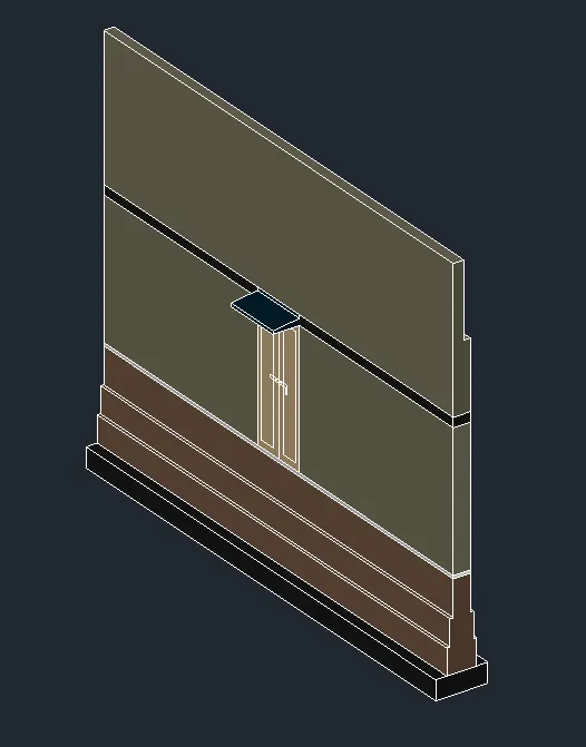
- Type in "RMAT" in the command line, a dialogue box with all the material listings will be displayed.
- Choose the materials from the given list according to the structure that is footing, wall, door, etc., and bring them into the upper column.
- Select the faces in the model one by one and assign them the material as per the property.
- Create the lighting effect and generate the rendered view of the 3d model
- Using the circle and extrude command, create a light pole of 5000mm height near the section.
- Go to visualization and click on the create light option.
- Choose the spotlight and place it over the pole created near the section.
- Direct the trajectory of the spotlight falling onto the object.
- Set up all the settings within the light that is falloff angle, highlight angle, intensity factor, lamp value, etc.
- Type in "RR" into the command panel to generate the 3d rendered view of the section.