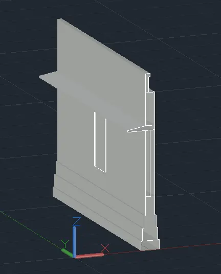
Creating 3D Isometric view of various structural elements in AutoCAD
Q1
AIM:-to create the plan and elevation of the building in 3D
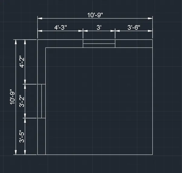
step 1:- to create a plan in 2D as per the given dimensions
- take a rectangle command
- specify the first point
- specify the next point as (10'9", 10'9")
- then take an offset command
- specify the offset distance as 9"
- create an offset of the rectangle
- then draw the window as per the given dimensions
step 2:- To create an elevation of the building
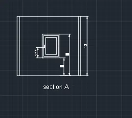
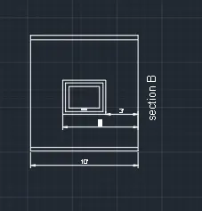
- take a line command
- create an elevation of the building with a height of 10'
- then create an elevation of the window with the single panel
- the window should be created at the sill level of 3'
step 3:- to create an isometric view of the building with the elevation of 10'
- change the drafting view to the isometric view
- take an extrude command
- select the walls of the building
- specify the extrude distance as 10'
- then subtract the object to create the opening for the window
- then rotate the elevation showing the elevation of the window taking a 3DROTATE COMMAND
- then place the elevation of the window at the opening created in the wall
- then the required image is created
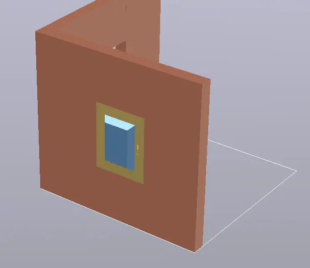
Q2
AIM:- To create an elevation of the building in 3D
step 1:-create a plan of the given figure as per the given dimension with a window opening
- take a line command
- specify the first point
- specify the next point as @10'9"
- specify the next point as @6'9"<0
- specify the next point as @10'9"<90
- then select c to close the rectangle
- take an offset command
- specify the offset distance as 9"
- select the object to be offsetted
- take a line command
- draw the window with the width of 3'
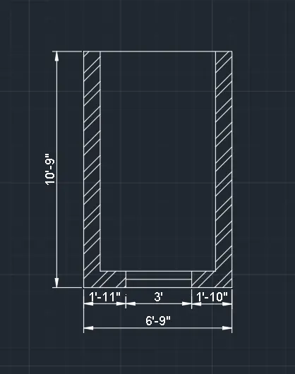
step 2:- to create a block showing the elevation of the window
- take a rectangle command
- specify the first point
- specify the next point as 3' x 4'
- then take an offset command
- select the object
- specify the offset distance as 3"
- then draw the rectangle showing the elevation of window panels as per the given dimensions
- then take a block command'
- select the objects
- Click on create a new block
- then the block of window elevation is created
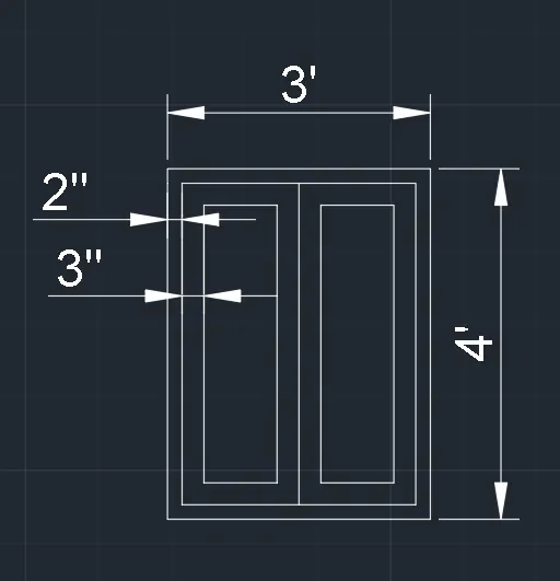
step 3:- To create an elevation of the room up to 4 stories
- change the view of the drawing to an isometric view
- take an extrude command'
- select the walls of the room
- extrude the walls up to the height of 10'
- subtract the object to create an opening for the window
- then select the block showing the elevation of the window
- take 3drotate command
- specify the rotation axis
- then copy the elevation of the window and place it over the opening created in the wall
- then take an extrude command'
- select the boundaries of the window and extrude to differentiate between the wall and window showing the sill level
- then select the total object
- take a copy command
- then copy the image to show the elevation of 4 stories
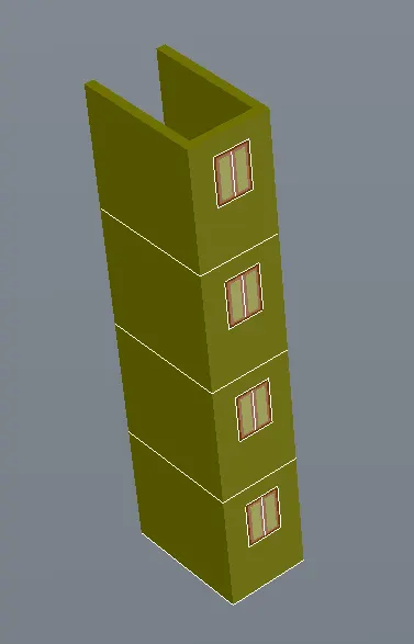
Q3
AIM:- To create the staircase in isometric view with a railing
- firstly change the drafting setting to 3d modeling
- then take a line command
- specify the first point and create a section of the staircase as per the given dimensions
- tread=1'
- rise=6"
- width of the step is given as 3'
- then take a extrude command
- select the section if the section
- specify the extrude distance as 3'
- change the view to the shaded
- create a railing of height 3'2"
- then the required image is obtained
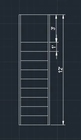
- PLAN OF THE STAIRCASE
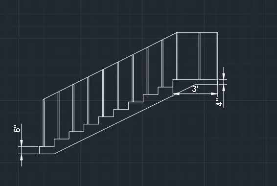
- SECTION OF THE STAIRCASE
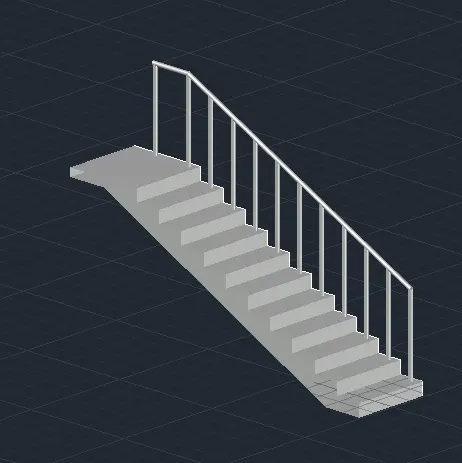
- SECTION OF THE STAIRCASE IN 3D VIEW
Q4
AIM:- to draw the section of the wall with lintel projection and door opening in 3D
- firstly change the drafting setting to 3dmodelling
- take a line command
- specify the first point and draw the section of the wall showing details of stepped footing, door, and the lintel as per the given dimensions
- then take a extrude command
- select the objects to be extruded
- specify the extrude distance as 7500
- then create an opening for the door
- draw the boundary of the door
- then subtract the shaded region of the door
- then the required realistic image of the door is created