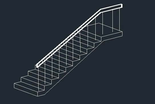
Creating 3D Isometric view of various structural elements in AutoCAD
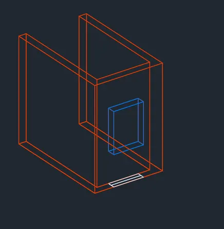
a1) aim - to create 3d isometric view of building
procedure - 1.create layers for the wall and windows
2. draw the line plan in XY plane according to layers allotted.
3. use boundary command on walls
4. mark them as region
5. use extrude command to give a height of 10'
6. only the wall layers will be extruded.
7. create a rectangle in place of the window, region it and make it extrude to a height of 10' till and then use union command
8.extrude the bottom rectangle to a height of 3' and then 4' to give window height
9. subtract the windown from the figure.
10. draw the window frames.
result - 1. elevation at A
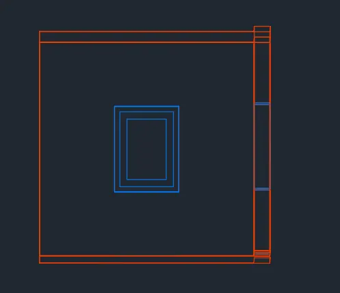
elevation at B
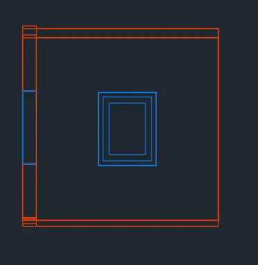
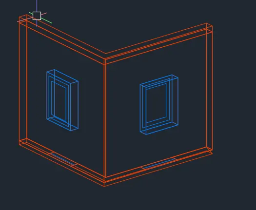
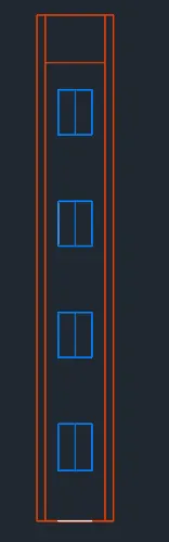
A2) to create a 3d view of building facade
procedure - 1. create the plan in the xy plane according to layers
2. mark it as a region and give the boundaries
3. extrude the wall and window to the suitable height
4. since the window have to be given separate distance they will ahve to be created seperately
5. create separate windows according to the distance betweeen them.
result -
single storey view
A3) aim - to create isometric 3d view of stairs
result -