Creating 3D Isometric view of various structural elements in AutoCAD
Name: Allan Bryan Jayson Cruz
Course: Master’s Certification Program in High-Rise Building Design & Analysis
Date: December 2, 2021
Challenge 12_ Creating 3D Isometric view of various structural elements inAutoCAD
********************************************************
1. Aim & Introduction
***************
Aim
This challenge aims to let the student utilize the tools in AutoCAD to create a 3D sketch. It aims to help the student familiarize with the different 3D commands present in the AutoCAD software. It also aims to help the student visualize 3D objects from 2D sketches.
Introduction
The AutoCAD software provides different tools. The tools used in this challenge is as described below:
Line - creates line object.
Polyline - creates connected line object.
Rectangle - creates rectangle object.
Circle - create circle object.
Trim - Cut unwanted lines or shapes with the provided cutting edges.
Extend - Extend lines to opposite corners.
Move - Move objects to particular locations.
Copy - Copy objects to particular locations.
Rotate - Rotate selected objects to a particular angle with respect to base point.
Array - Copy an object in a set path linearly or polarly.
Join – Joins separated line objects into one object. Line to polyline.
Dimlinear (DLI) - Provides vertical or horizontal linear/straight dimensions.
Dimaligned (DAL) - Provides aligned dimensions.
Dimangular (DAN) – Provides angular dimensions.
Quickdimension (QDIM) – Provides quick dimension of a geometry.
Leader - Creates an arrowhead line.
Layers - Provide identification of line or object groups by their properties.
Units - Open "Drawing Units" window to specify the drawings units.
Dimstyle - Open "Dimension Style Manager" window to modify the dimension properties.
Hatch - Provides hatching pattern in a given object or internal point.
Layer - Open the layer tab which manages the line properties in a drawing.
********************************************************
2. Sketch and Procedure
***************
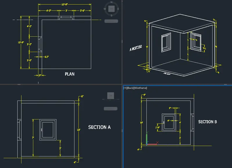
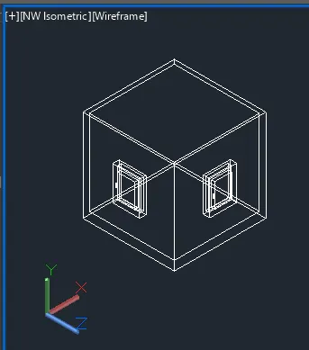
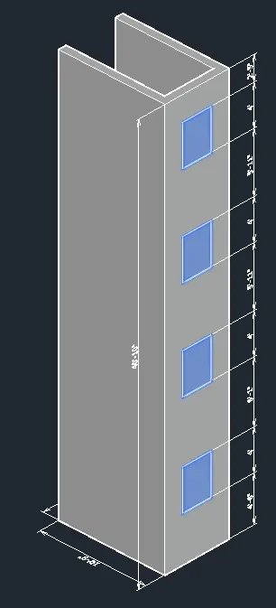
A. Create a 3D Isometric View of the building with plan and elevation given.
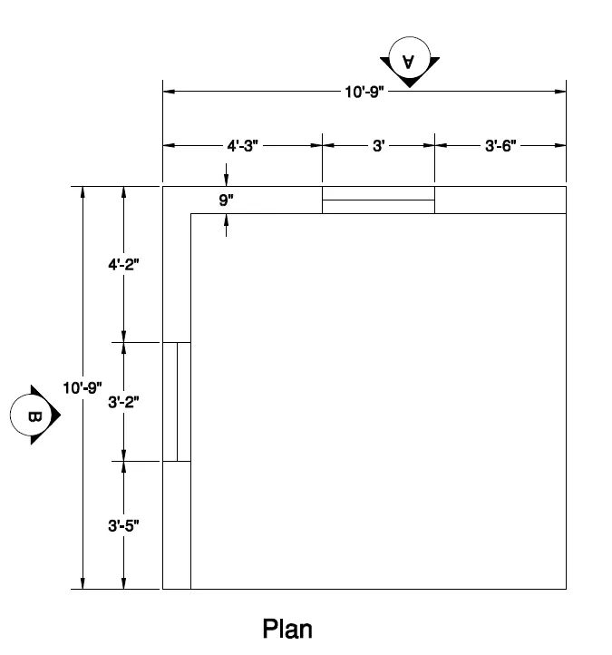
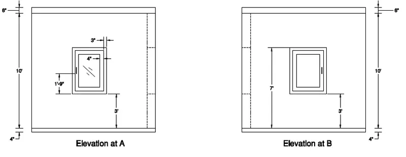
PROCEDURE:
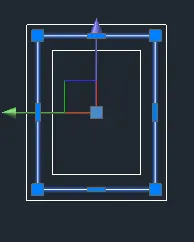
- Draw the 2D plan.
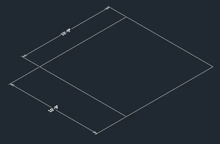
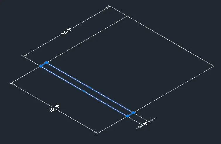
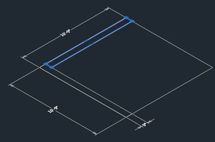
- Trim and join the 2 rectangles.
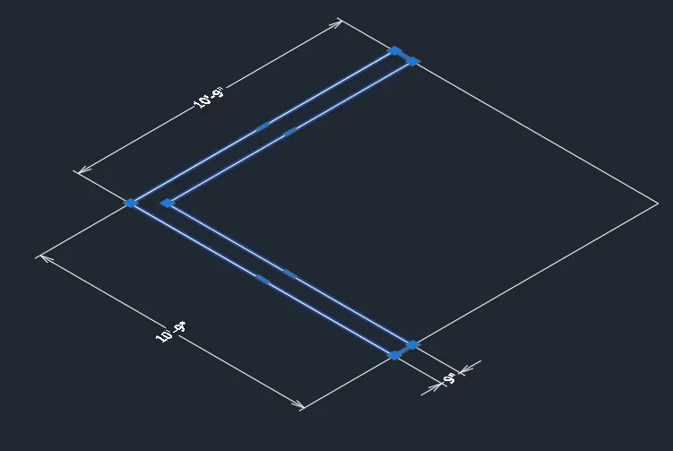
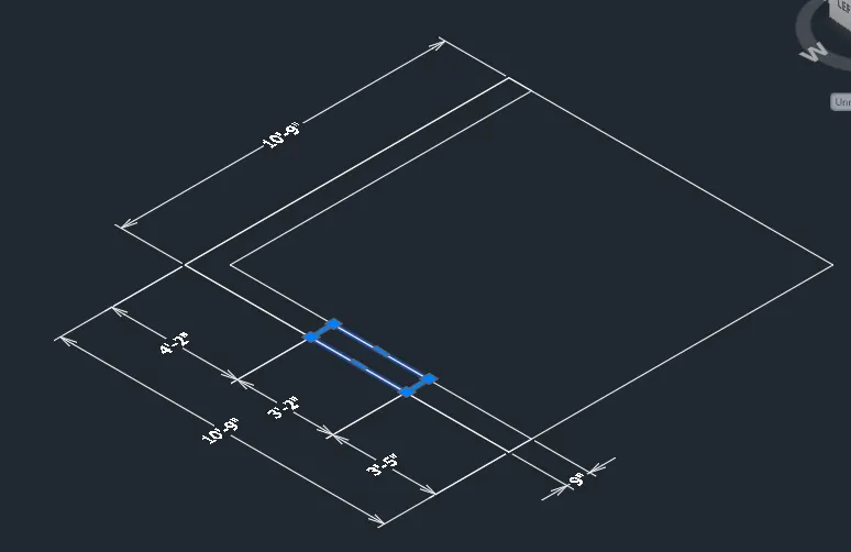
- You can use the Top View for better view.
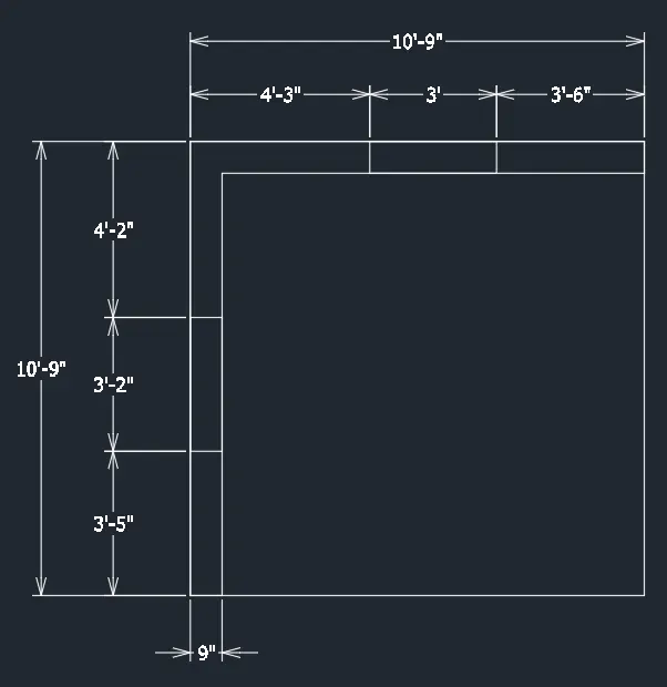
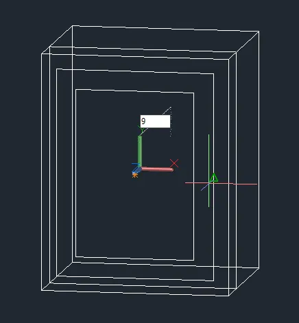
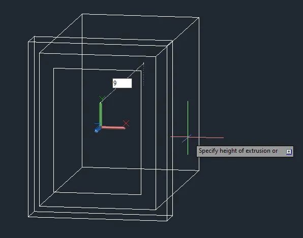
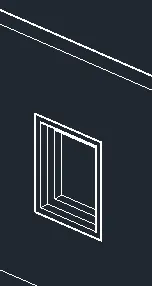
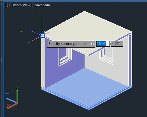
- Extrude and change the elevation.
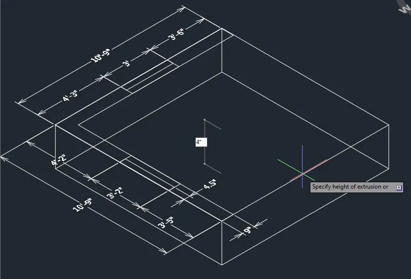
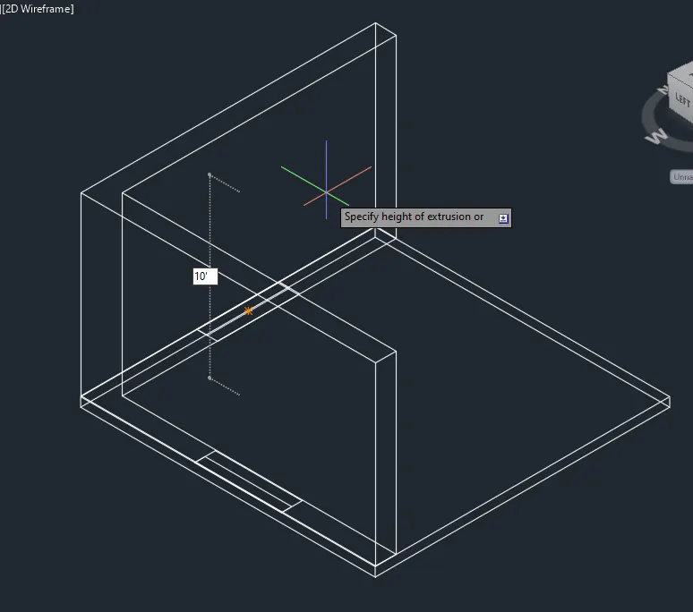
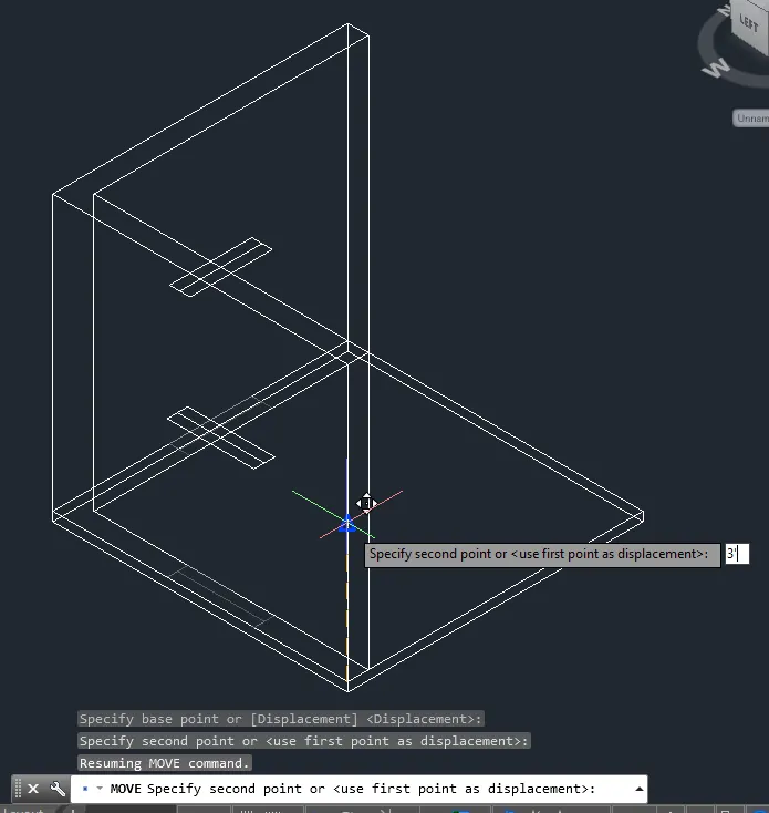
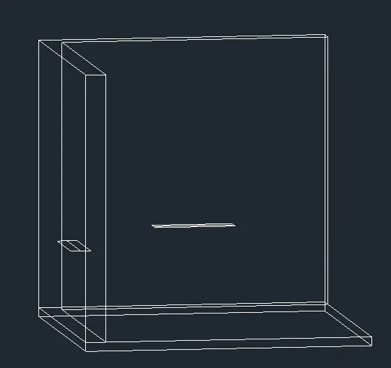
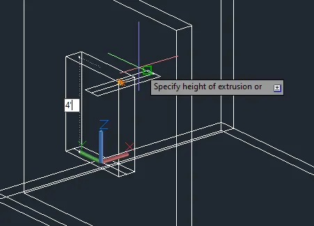
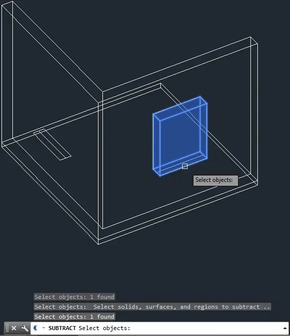
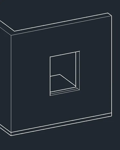
- Go to left view and add the window. Extrude afterwards.
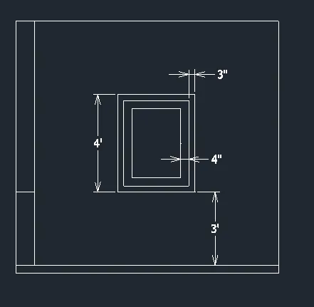
- Extrude and Trim.
- Do the same procedure again.
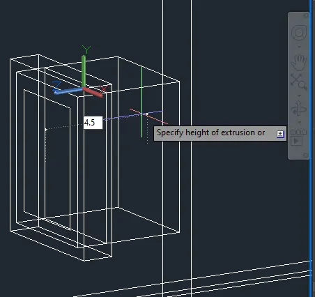
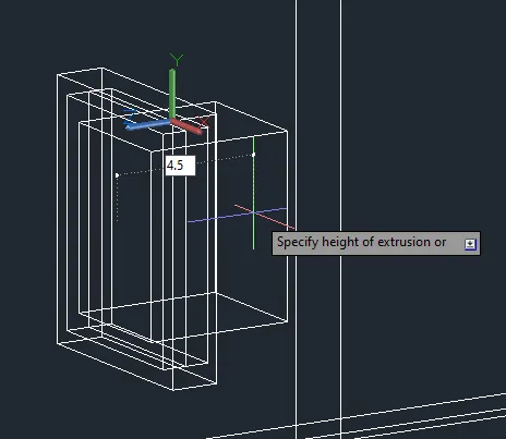
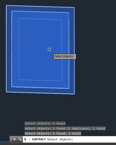
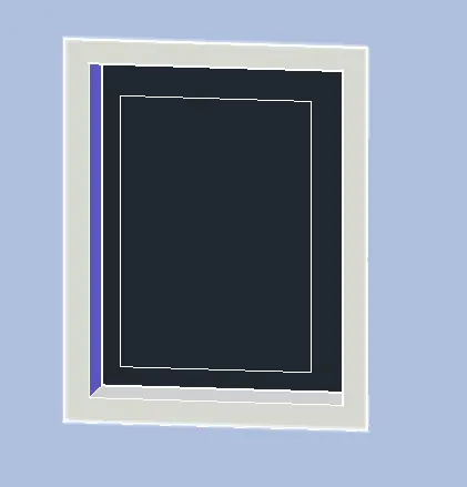
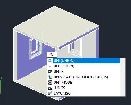
- Then subtract.
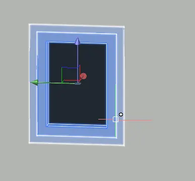
- Add 3D face for the window glass.
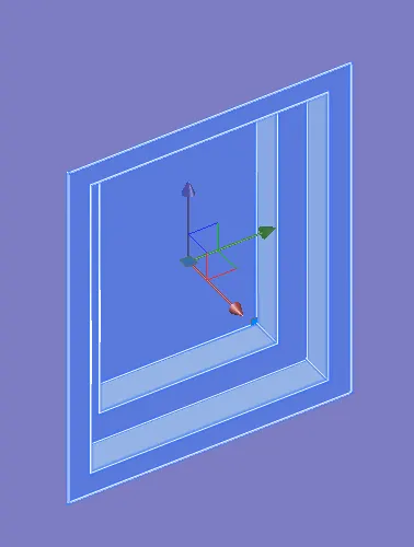
- Do the same for the other window.
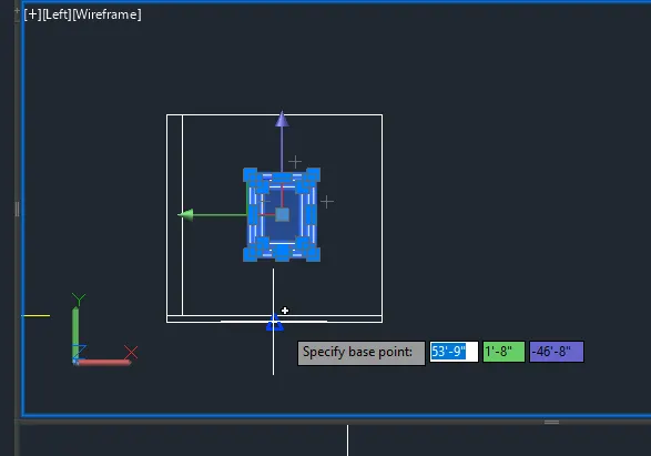
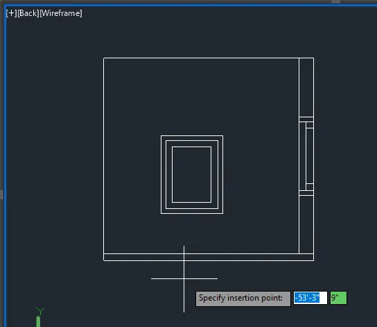
- Subtract.
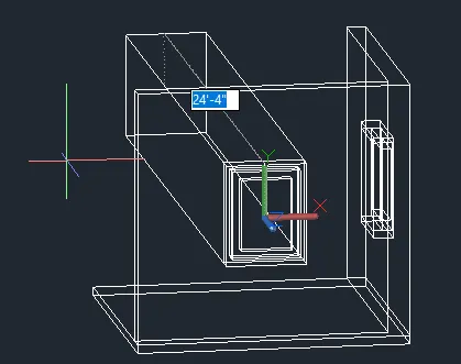
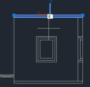
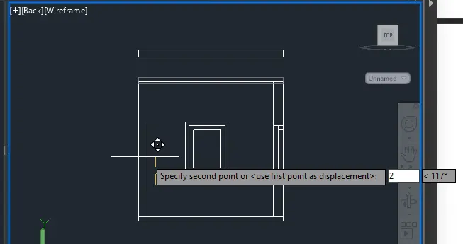
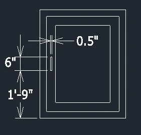
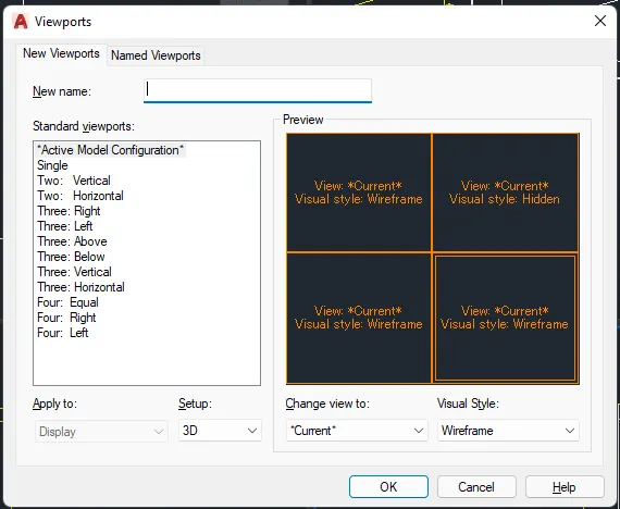
- Add dimension to finish.
FINAL PRODUCT:
***************
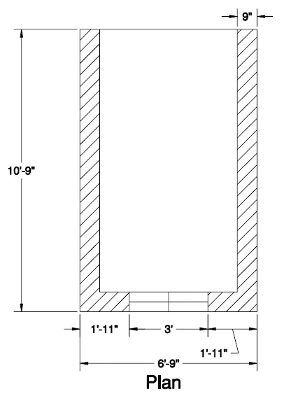
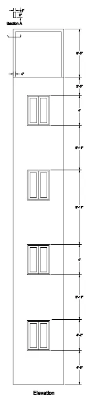
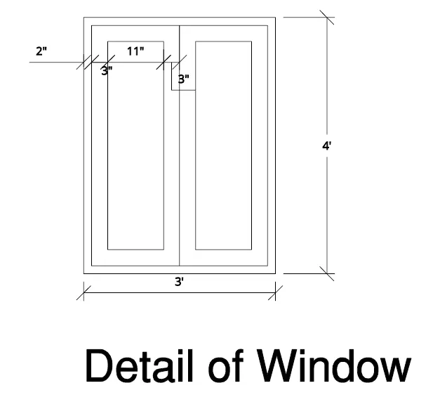
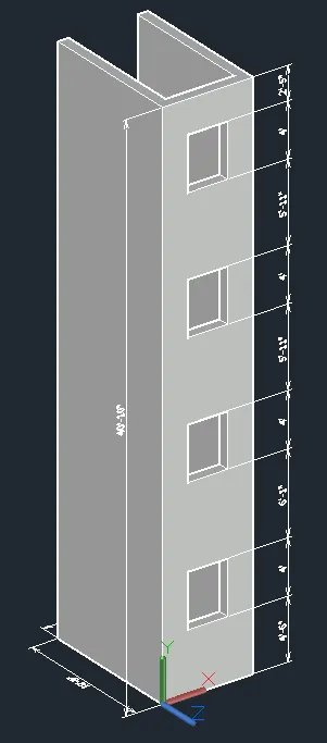
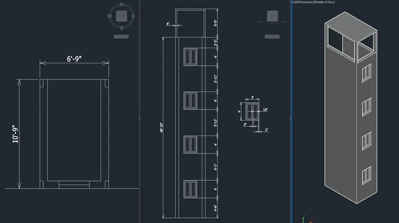
B. Create the 3D View of the Building Façade as given in the plan and elevation. Also, see the detail of the window.
PROCEDURE:
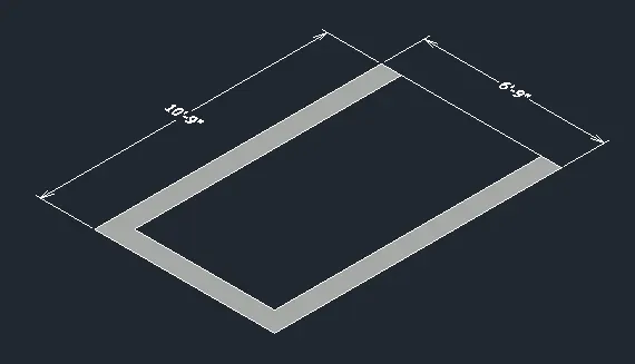
- Create 2D plan.
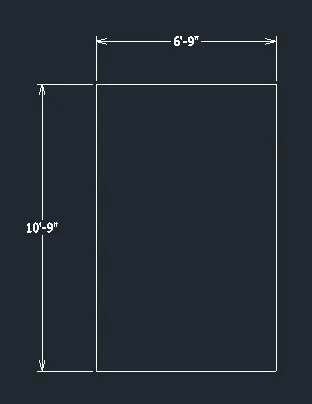
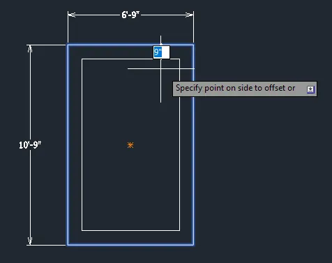
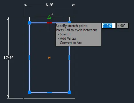
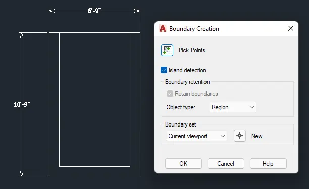
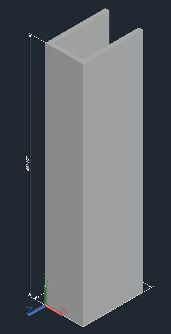
- Extrude.
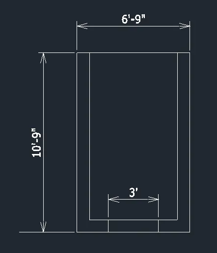
- Go to the plan and draw the window opening.
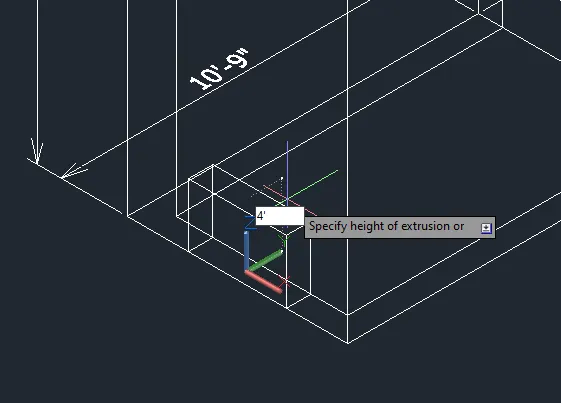
- Move to the correct location.
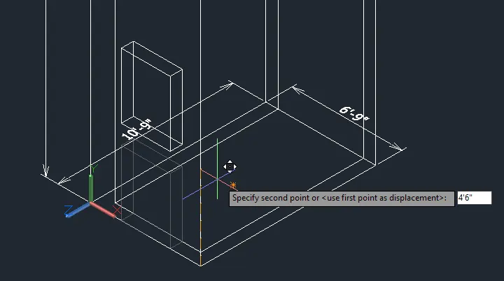
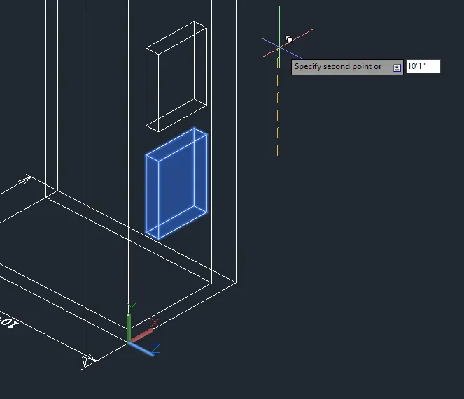
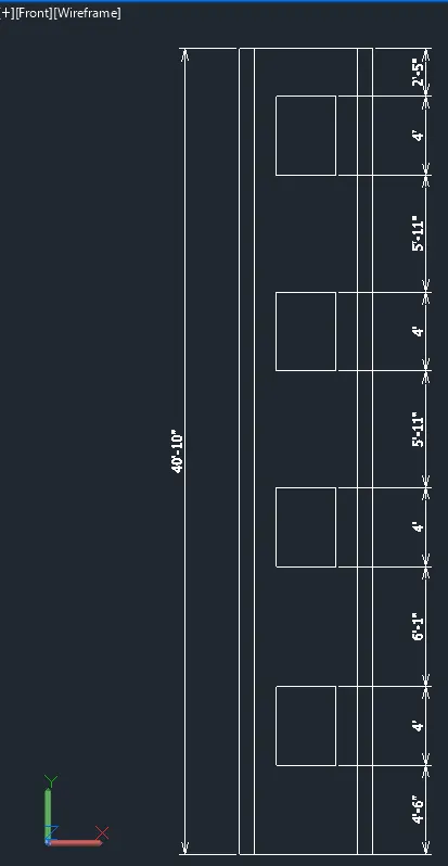
- Subtract the solids.
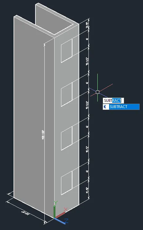
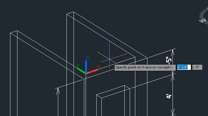
- Create the top part.
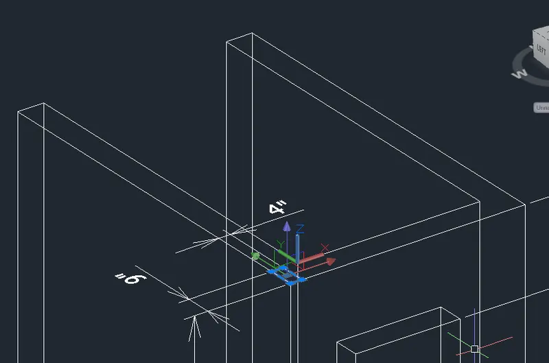
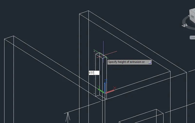
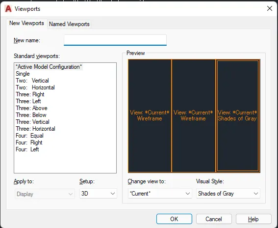
- Copy to 4 sides.
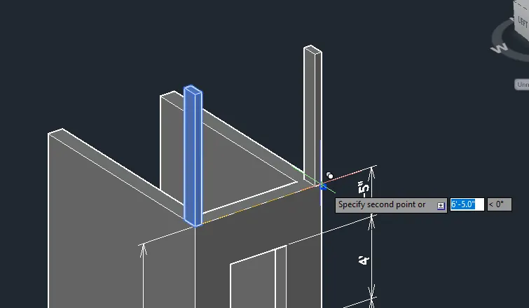
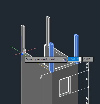
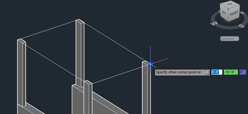
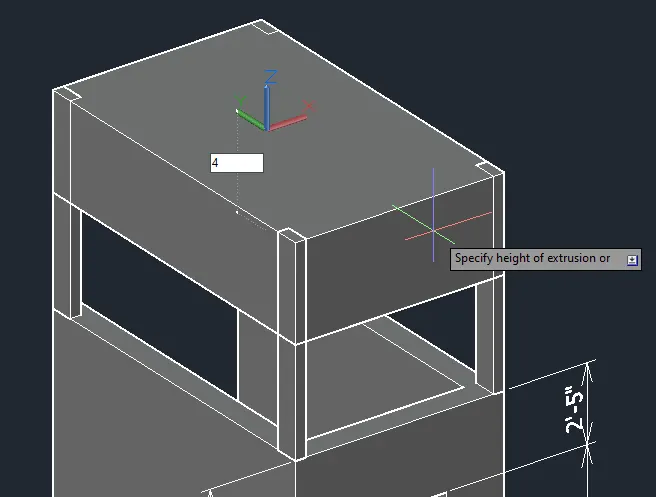
- Then union them all together.
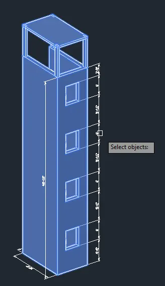
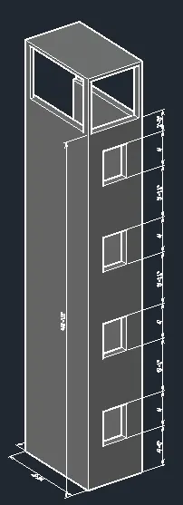
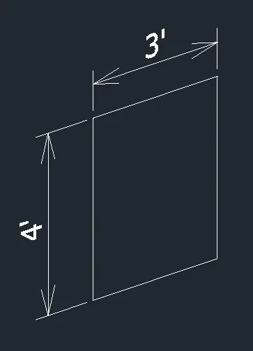
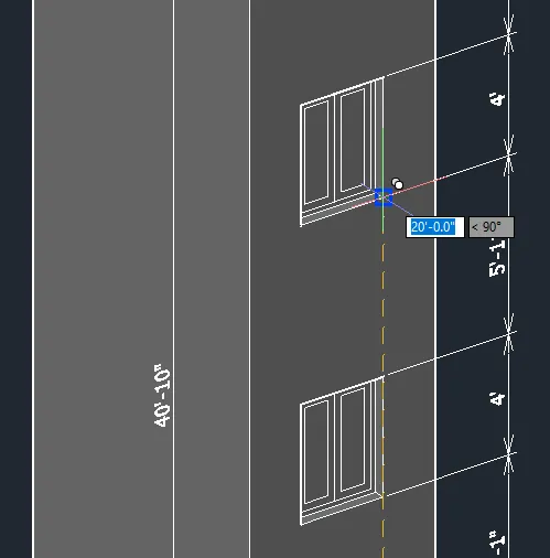
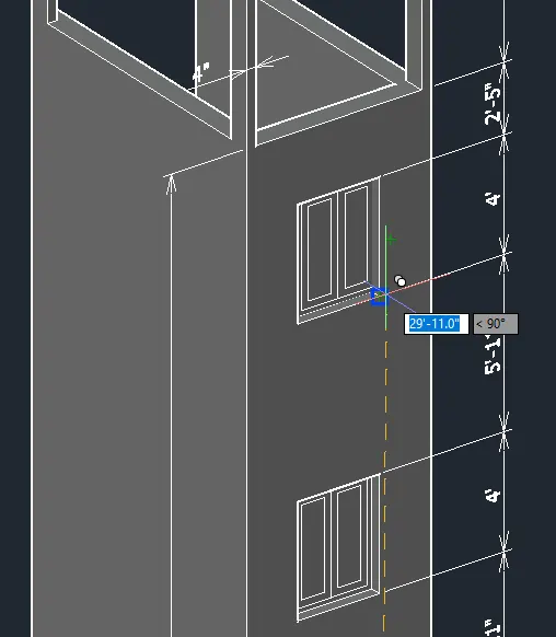
- Go to front view and draw the window detail in 2D.
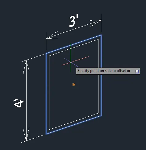
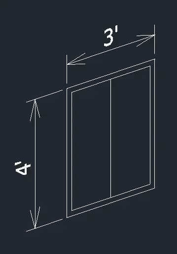
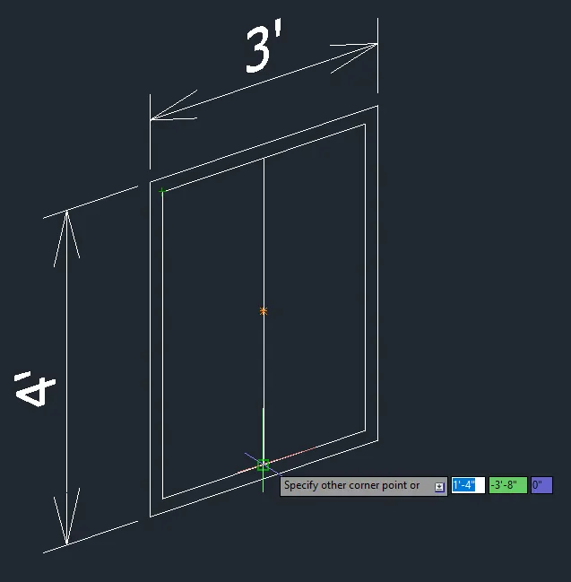
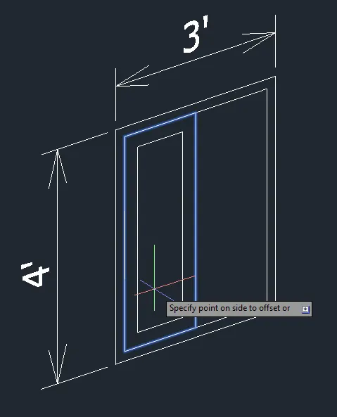
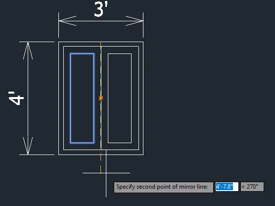
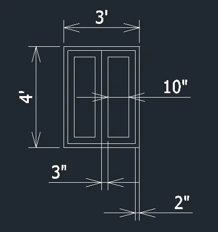
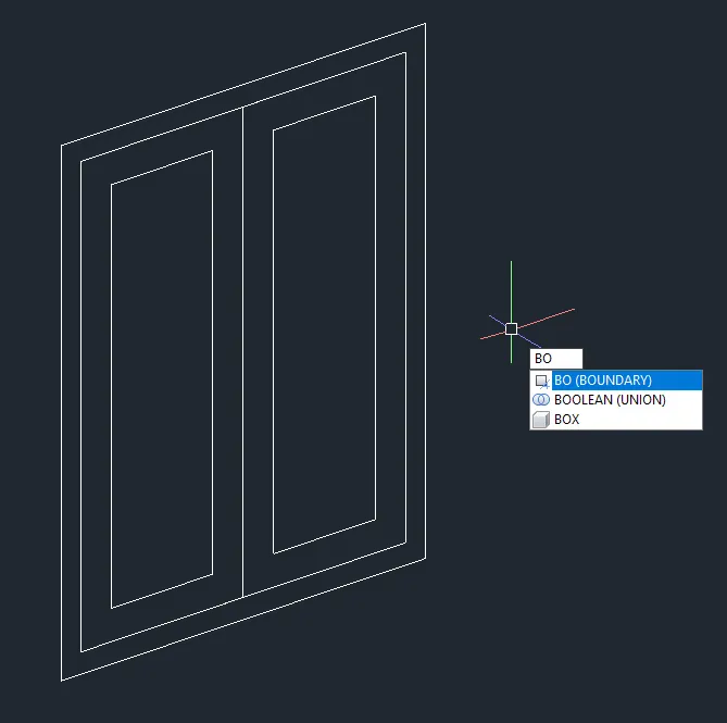
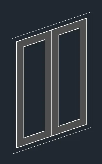
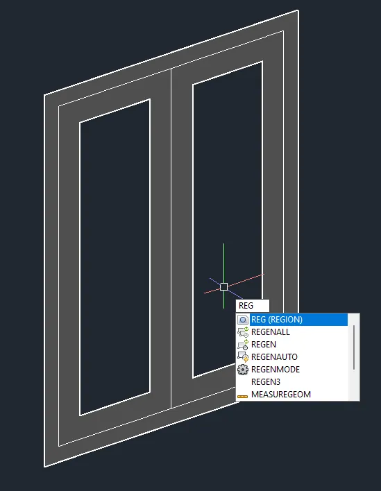
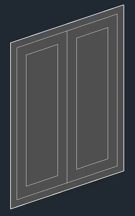
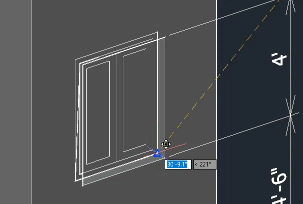
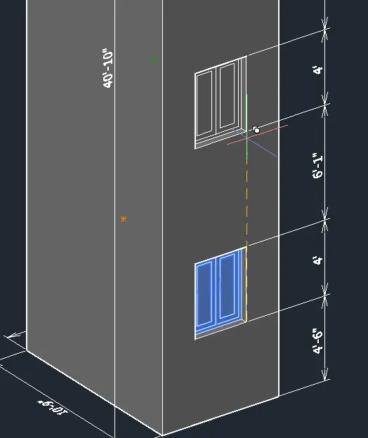
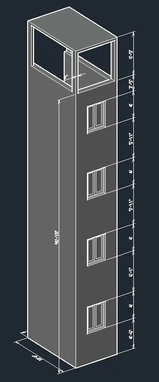
FINAL PRODUCT:
***************
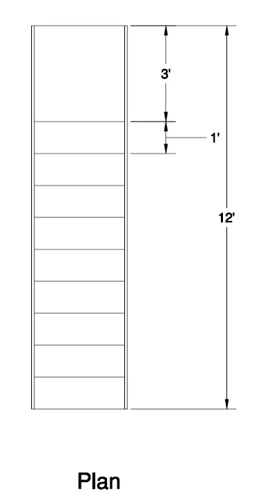
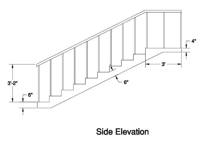
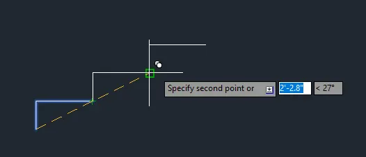
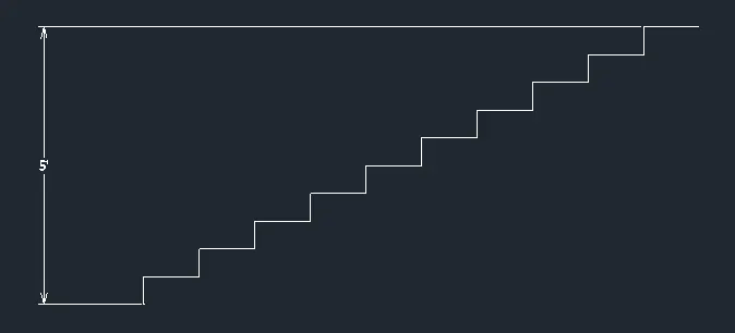
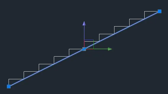
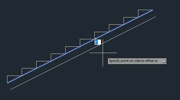
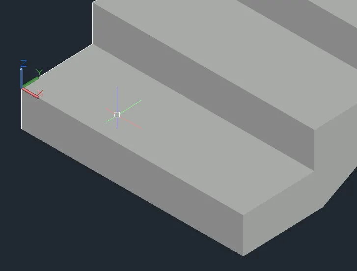
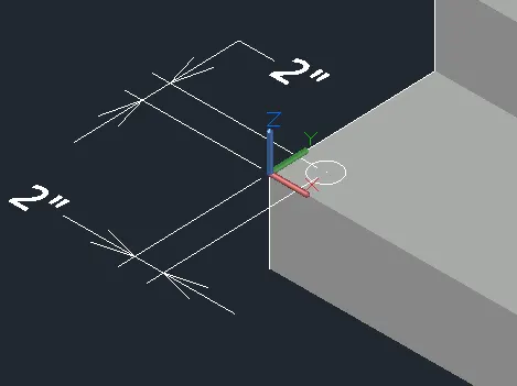
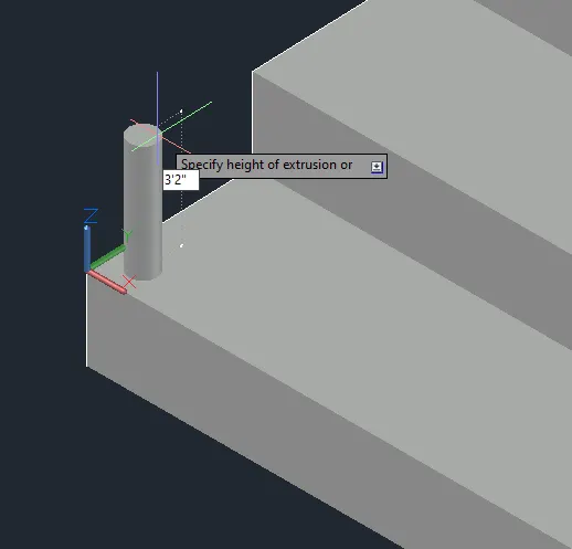
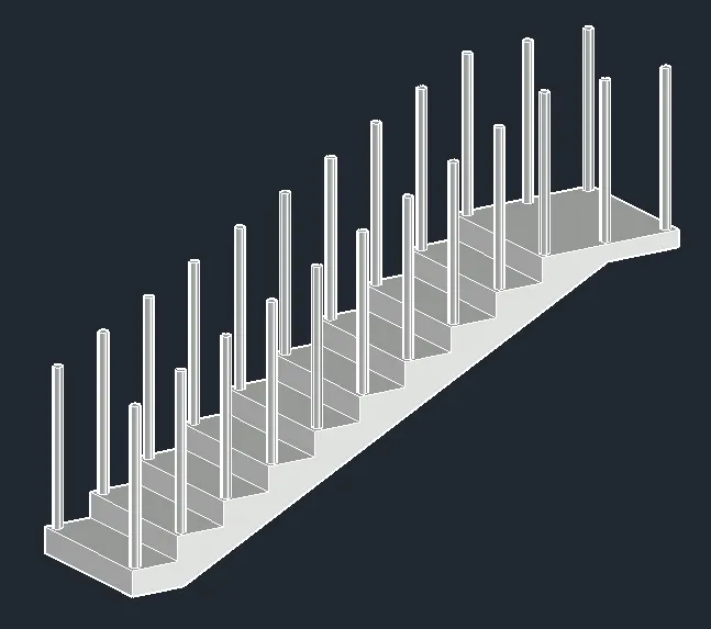
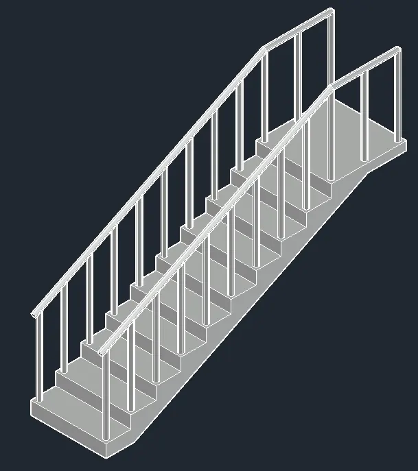
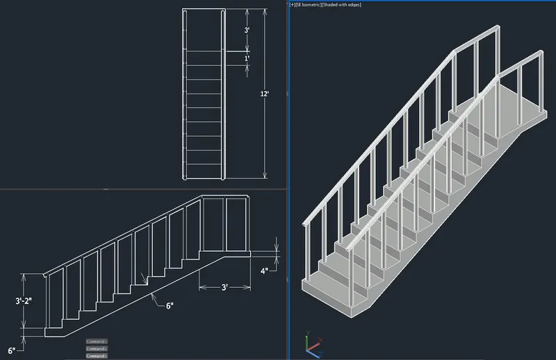
C. Create the isometric 3d view of a stair with railing as shown in the plan and elevation. Assume the size of the balustrades and the handrails.
PROCEDURE:
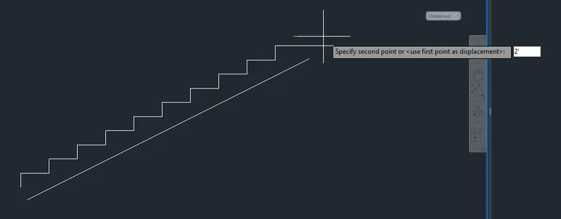
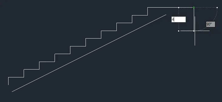
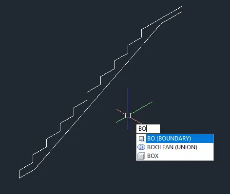
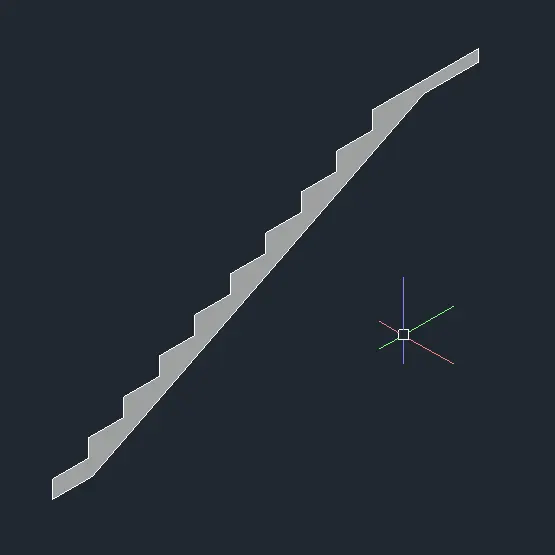
- Create the 2D right side view.
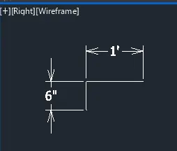
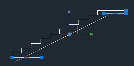
- Fillet with radius 0.
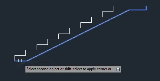

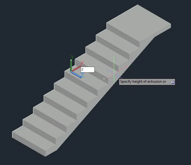
- Go to isometric view and extrude.
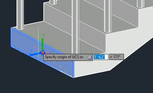
- Draw the handrail.
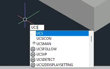
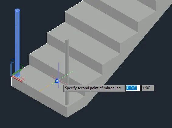
- Copy the handrail.
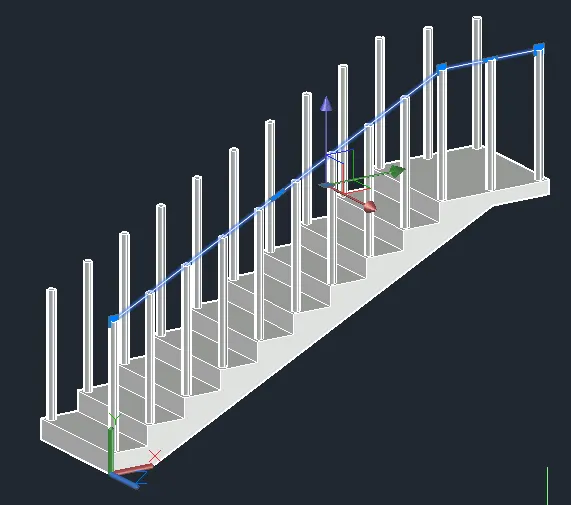
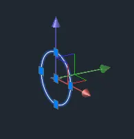
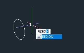
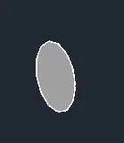
- Sweep the region along the path.
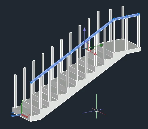
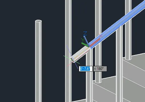
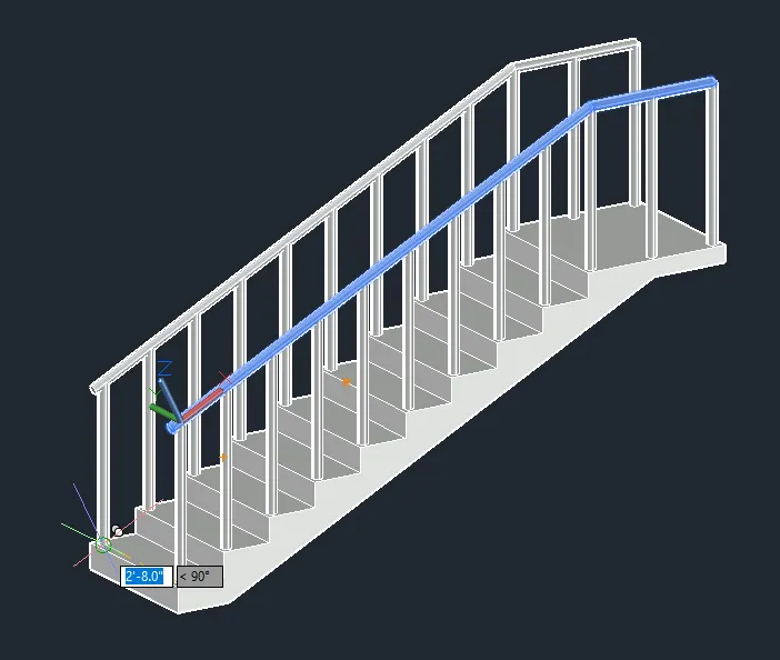
- Add dimensions and finish.
FINAL PRODUCT:
***************
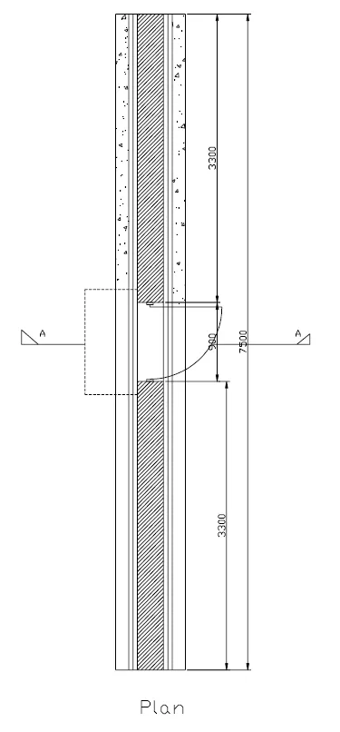
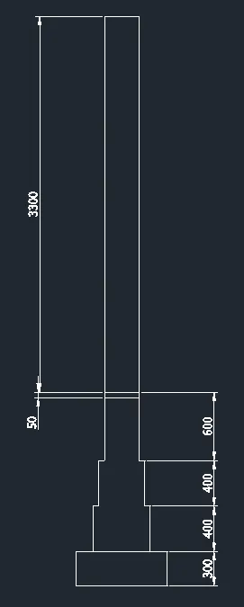
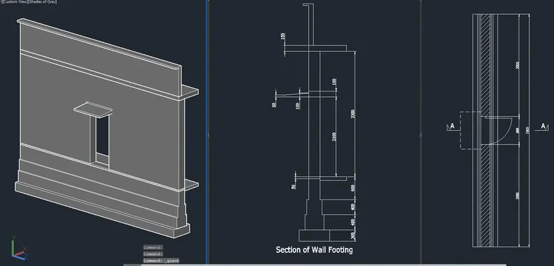
D. Create the 3D view of a Wall with spread footing. Create the Door opening only. Assume the size of the parapet and the coping. See the plans and elevation for the details. Also, create a rendered view of the model with materials as of your choice.
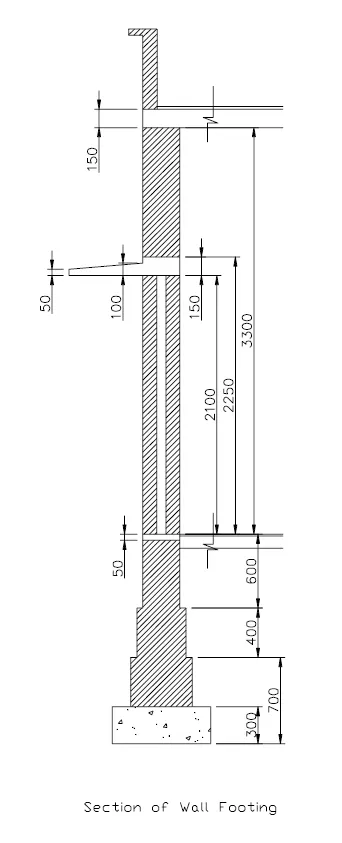
PROCEDURE:
- Proceed with the 2D plan.
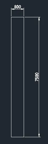
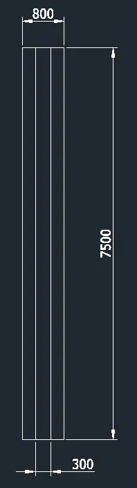
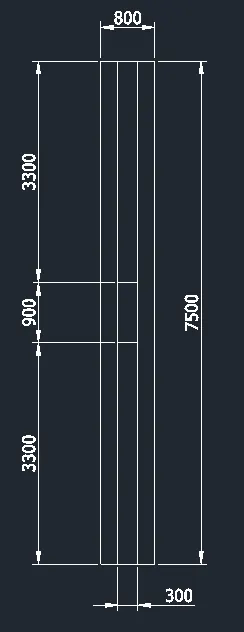
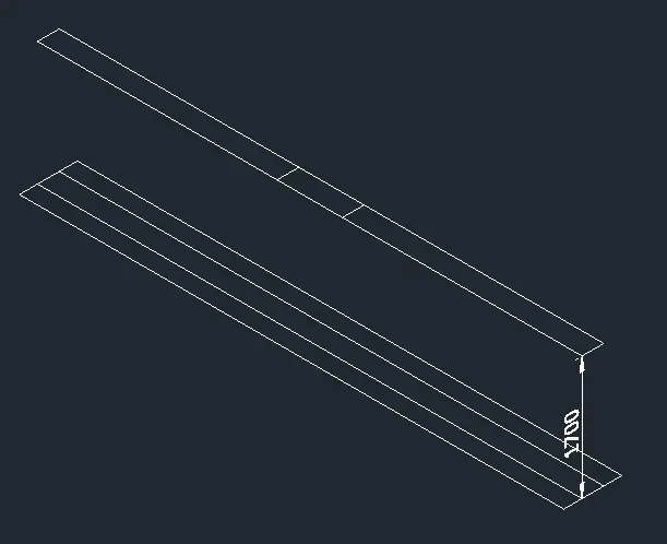
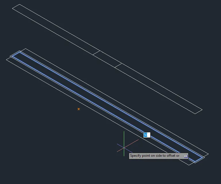
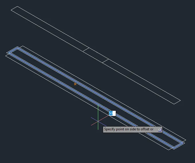
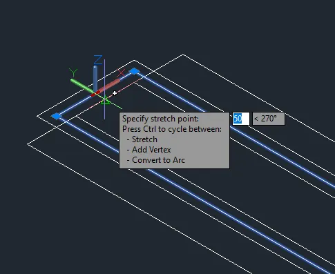
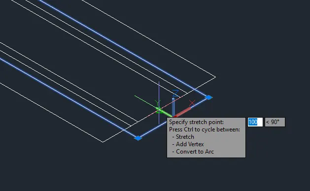
- Change the elevations.
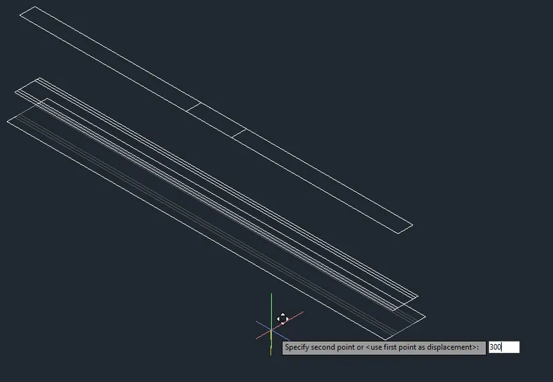
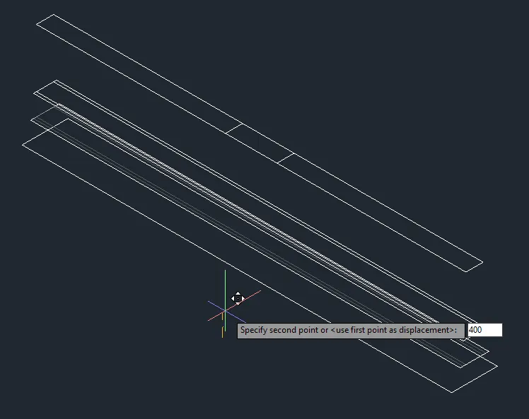
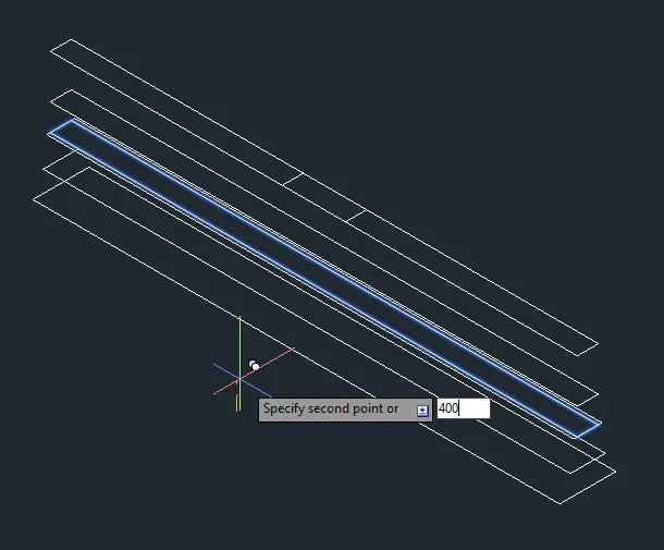
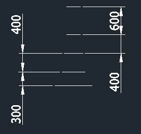
- Extrude.
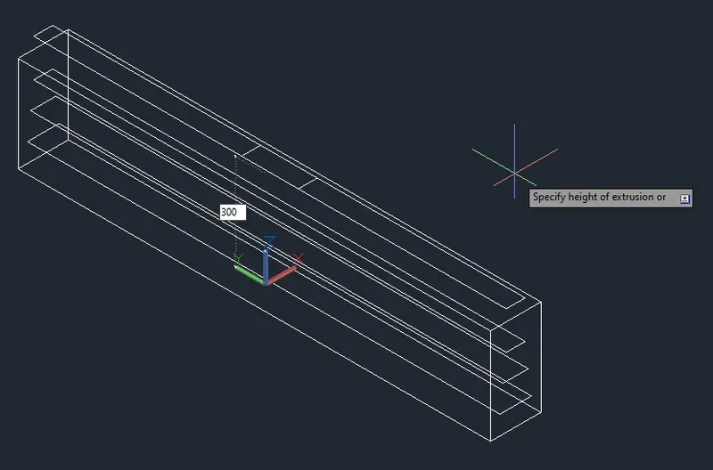
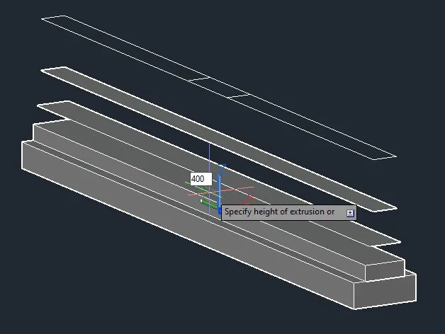
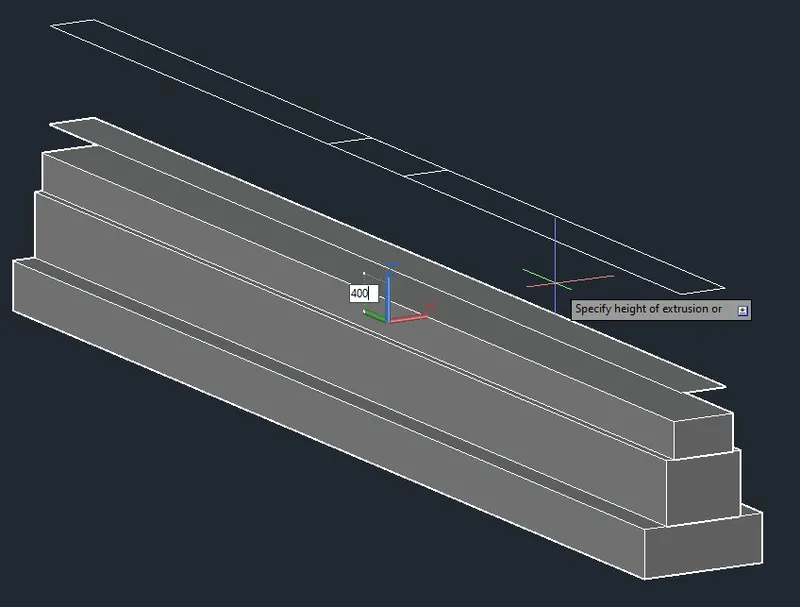
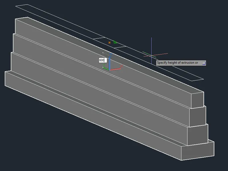
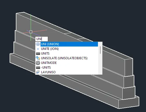
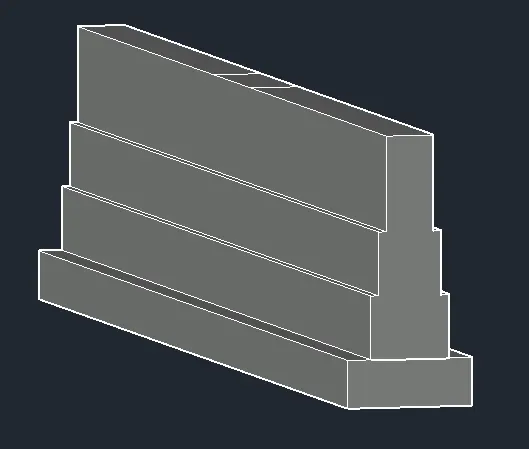
- Go to front view.
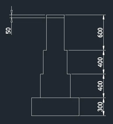
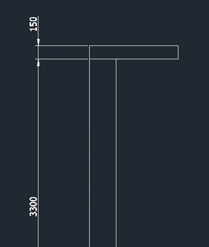
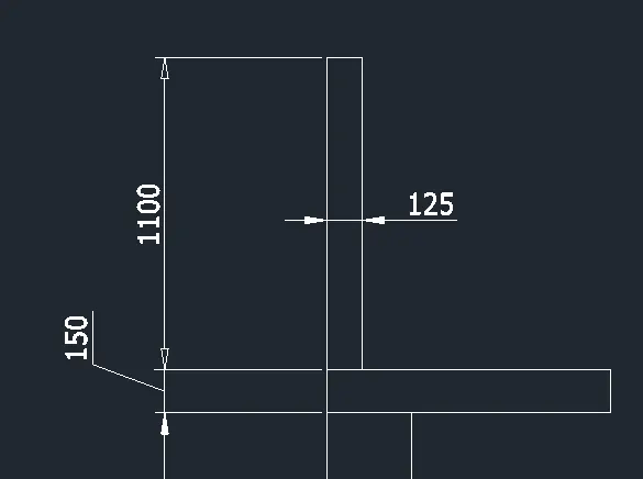
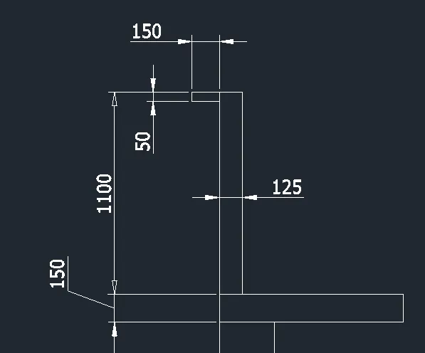
- Trim and join.
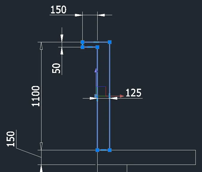
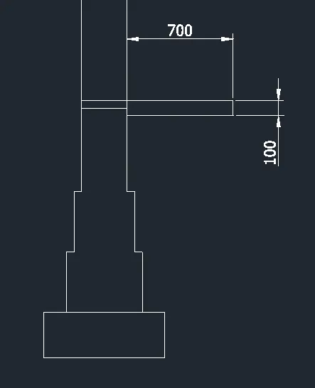
- Sketch the canopy.
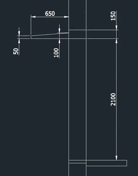
- Extrude.
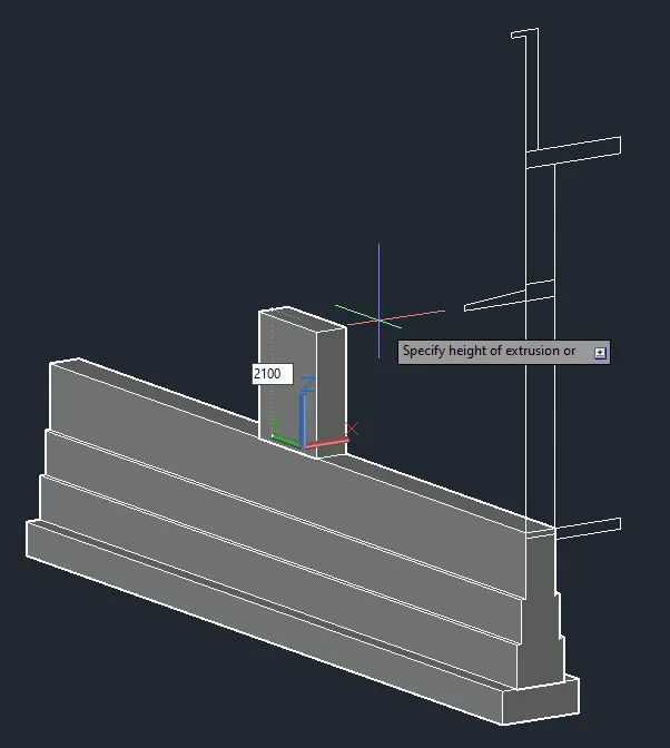
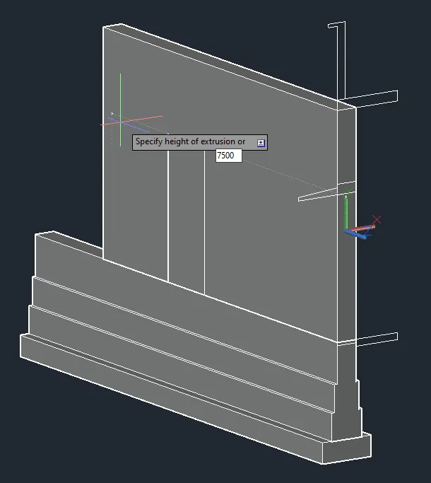
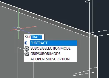
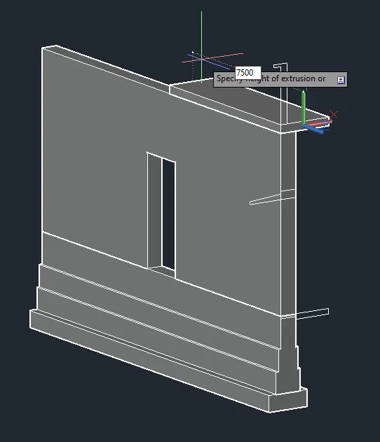
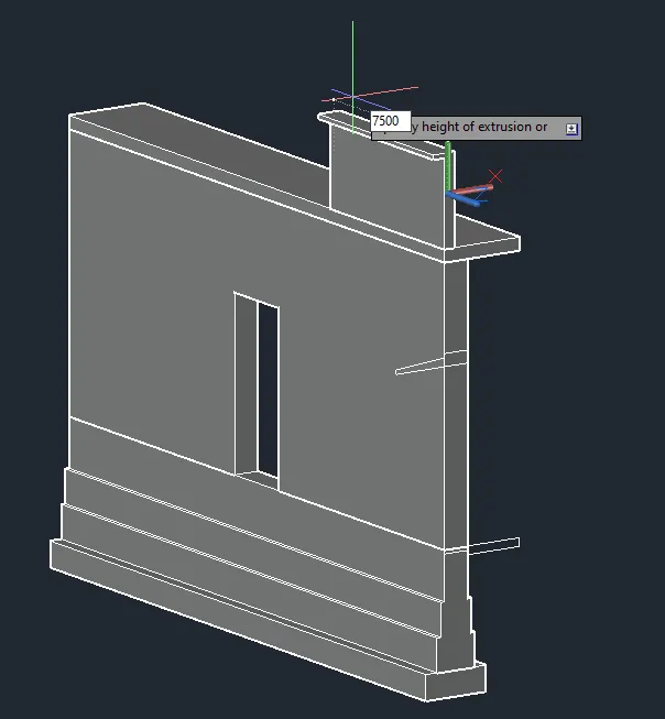
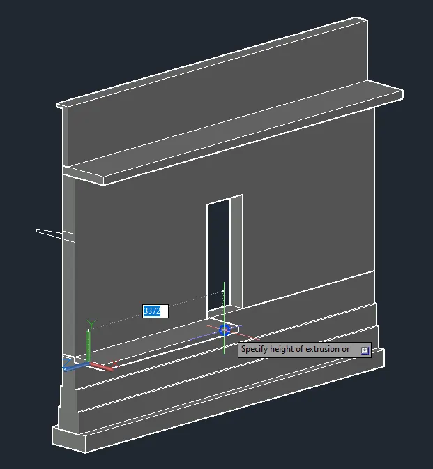
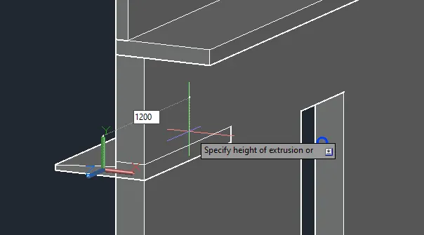
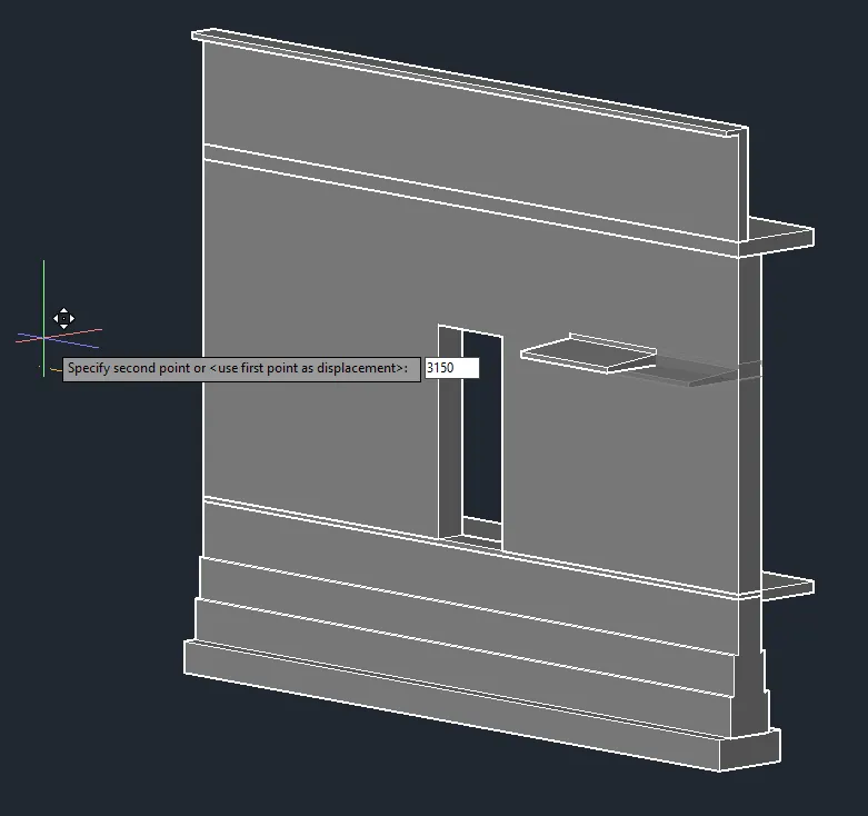
- Create views.
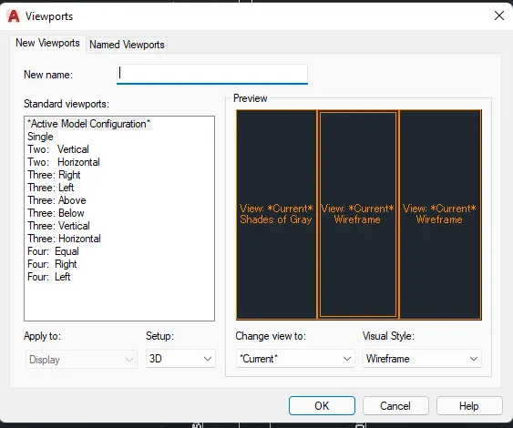
FINAL PRODUCT:
********************************************************
3. Conclusion
***************
The AutoCAD software allows 3D sketches where solid objects or 3D surfaces are present. By using the 3D function of the AutoCAD software, one can illustrate or convert a 2D sketch into a 3D illustration.
With AutoCAD, you can also visualize your sketches into 3D. The AutoCAD software allows the creating of views scuh as top view, front view, and perspective view.