Creating 3D Isometric view of various structural elements in AutoCAD
AIM -
To create a 3D isometric view of the given building with plan and elevation.
INTRODUCTION:-
- An isometric drawing is a 3D representation of an object, room, building or design on a 2D surface.
- One of the defining characteristics of an isometric drawing, compared to other types of 3D representation, is that the final image is not distorted.
- This is due to the fact that the foreshortening of the axes is equal.
- In an isometric drawing, the object appears as if it is being viewed from above from one corner, with the axes being set out from this corner point.
- Isometric drawings begin with one vertical line along which two points are defined.
- Any lines set out from these points should be constructed at an angle of 30 degrees.
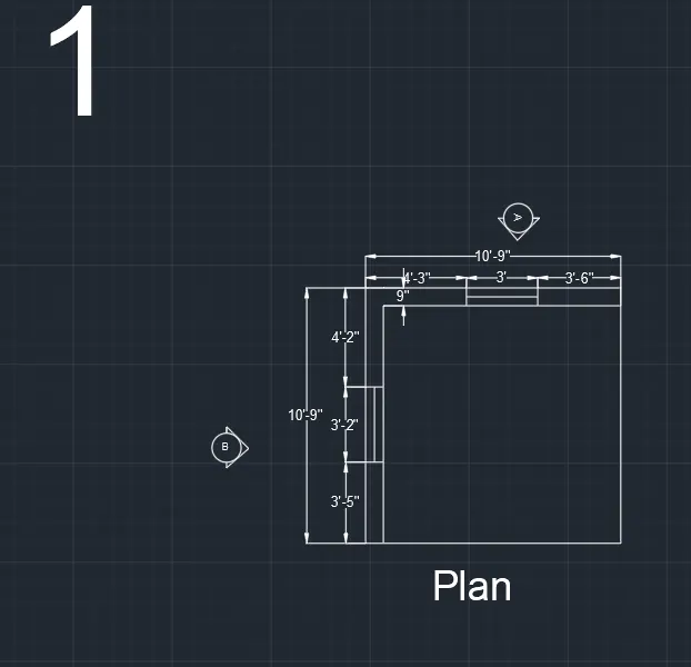
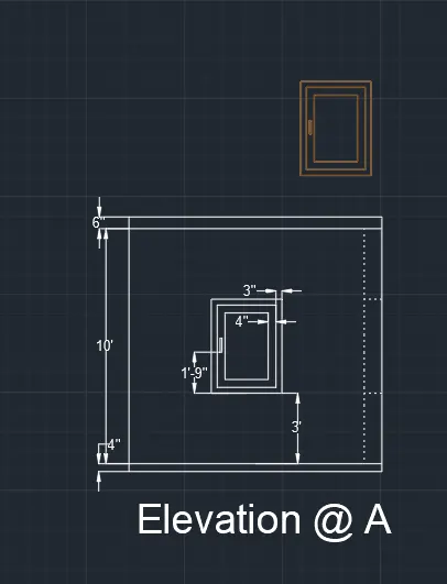
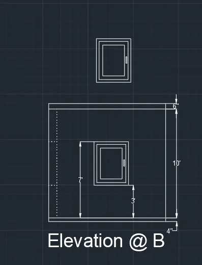
- A plan view of wall of two elevation views of windows on both sides are given and they are to be converted into a 3D model. 2 window openings on both sides are given with details regarding the frame dimensions, mullion dimensions and handle height. The thickness of bottom floor and top roof are also given as 4” and 6” respectively. The height of floor is given as 10’. Height of window from the floor is 3’.
COMMANDS USED:-
- Line command
- Rectangle command
- UCS command
- Dimlinear command
- Region command
- Extrude command
- Substract command
- Box command
- Units command
- Dimstyle command
- 3Dface command
- 3Dorbit command
- Hide command
- Explode command
- Move command
- Copy command
- Dist command
- Solidedit command
- Union command
- Boundary command
- 3D mirror command
- 3D rotate command
- Erase command
PROCEDURE:-
- Open AutoCAD
- In Startup settings start from scratch select Imperial (Feet and Inches)
- Open grid and snap settings
- Change snap and grid spacing to 1’
- Change major line every grid line to 10
- Turnoff adaptive grid
- Type ‘un’ in command box and press enter
- Change units’ type to decimal and precision to 1’1/16” and insertion scale to inches
- Change the workspace setting of AutoCAD from ‘drafting and annotation’ to ‘3D Modeling’
- Open Layer properties and create new layers by clicking on new layer or right click on any layer and select new layer to create new layer
- Layers are created as follows.
- Change the current layer to 3D_Wall
- Create a rectangle of dimensions 10’9”X10’9” at any point on the screen
- Offset the rectangle to inside to distance of 9” as wall thickness
2.Create the 3D View of the Building Façade as given in the plan and elevation.
INTRODUCTION:-
- An isometric drawing is a 3D representation of an object, room, building or design on a 2D surface.
- One of the defining characteristics of an isometric drawing, compared to other types of 3D representation, is that the final image is not distorted.
- This is due to the fact that the foreshortening of the axes is equal.
- In an isometric drawing, the object appears as if it is being viewed from above from one corner, with the axes being set out from this corner point.
- Isometric drawings begin with one vertical line along which two points are defined.
- Any lines set out from these points should be constructed at an angle of 30 degrees.
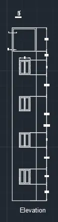
- A plan view of wall of two elevation views of windows on both sides are given and they are to be converted into a 3D model. 2 window openings on both sides are given with details regarding the frame dimensions, mullion dimensions and handle height. The thickness of bottom floor and top roof are also given as 4” and 6” respectively. The height of floor is given as 10’. Height of window from the floor is 3’.
COMMANDS USED:-
- Line command
- Rectangle command
- UCS command
- Dimlinear command
- Region command
- Extrude command
- Substract command
- Box command
- Units command
- Dimstyle command
- 3Dface command
- 3Dorbit command
- Hide command
- Explode command
- Move command
- Copy command
- Dist command
- Solidedit command
- Union command
- Boundary command
- 3D mirror command
- 3D rotate command
- Erase command
PROCEDURE:-
- Open AutoCAD
- In Startup settings start from scratch select Imperial (Feet and Inches)
- Open grid and snap settings
- Change snap and grid spacing to 1’
- Change major line every grid line to 10
- Turnoff adaptive grid
- Type ‘un’ in command box and press enter
- Change units’ type to decimal and precision to 1’1/16” and insertion scale to inches
- Change the workspace setting of AutoCAD from ‘drafting and annotation’ to ‘3D Modeling’
- Open Layer properties and create new layers by clicking on new layer or right click on any layer and select new layer to create new layer
- Layers are created as follows.
- Change the current layer to 3D_Wall
- Create a rectangle of dimensions 10’9”X10’9” at any point on the screen
- Offset the rectangle to inside to distance of 9” as wall thickness