Creation of Multiple viewports, Scaling the drawing and setting in Template in AutoCad
1. LAYOUT OF THE PLAN AND SECTION A
https://web.autocad.com/acad/me/sid/shares/drawings/82f6231c-fd27-45a1-a9af-cc8e05cd38c1/editor
PROCEDURE-
Type xref in command box and press enter
- Click on ‘Attachement’.Keep scale as 1.
- Click on insertion point as specify on screen.
- Click on okay and specify the point of insertion.
- Right click on the layout tab.
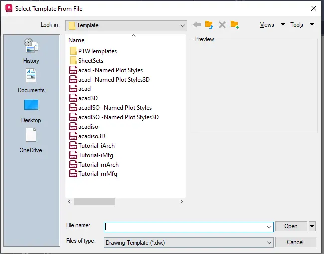
- Click on ‘From template’.
- From pop up click on ‘Tutorial-mArch’.
- Right click on layout and click on rename and type ‘Floor Plan-Section AA’
Go to model tab
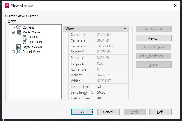
- Type ‘v’ and press enter.
- Click on new.
- Type name as ‘Floor Plan’.
- Click on define window.
- Select the Floor Plan.
- Click on new.
- Type name as ‘Section AA’.
- Click on define window.
- Select the Section view
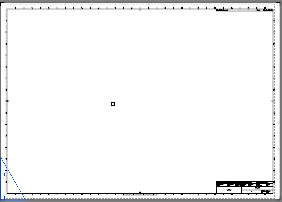
Go to Paper space or ps.
- Type mv in command box and click on object in command box.\
- Select the object to viewport as first rectangle drawn
Go to model space or ms.
- Type v and press enter.
- Select the Floor Plan view created and click on set current and click okay.
- Change the scale to 1:50 and pan the figure to adjust
Go to paper space or ps.
- Type mv in command box and click on object in command box.
- Select the object to viewport as second rectangle drawn.
Go to model space or ms.
- Type v and press enter.
- Select the Section AA view created and click on set current and click okay.
- Change the scale to 1:50/2% and pan the figure to adjust
Go to paper space or ps.
- Select the two viewports created and go to properties.
- Change the display locked to ‘YES’
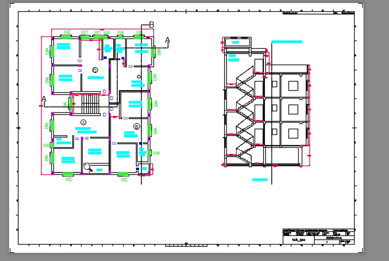
RESULT-
LINK- https://web.autocad.com/acad/me/sid/shares/drawings/82f6231c-fd27-45a1-a9af-cc8e05cd38c1/editor
2. CREATE A LAYOUT OF THE KITCHEN
https://web.autocad.com/acad/me/sid/shares/drawings/e32bbf15-c3fb-47b2-99fb-3a27f4602102/editor
PROCEDURE-
Creating Layout
Go to layout tab and delete the current viewports available
- Right click on the layout tab
- Click on rename and type ‘Kitchen Layout A4’
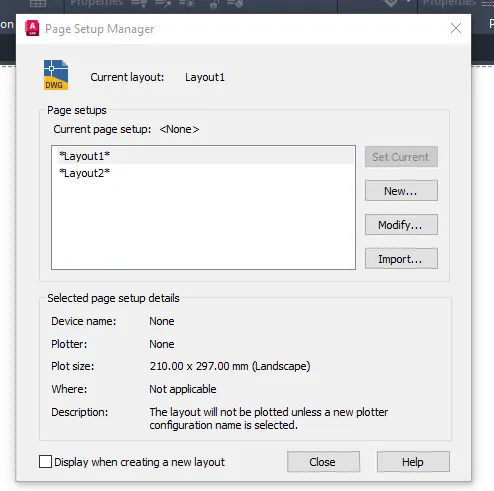
- Go to Page setup manager
- Click on new
- Set name as A4
- Change printer to AutoCAD PDF
- Set paper size as ISO full bleed A4
- Change plot area to ‘Layout’
- Click okay
Creating Views
- Go to model tab
- Type ‘v’ and press enter
- Click on new
- Type name as ‘Below contour plan’
- Click on define window
- Select the below contour plan view
- Click on new
- Type name as ‘Above contour plan’
- Click on define window
- Select the above contour plan view
Creating Viewport views
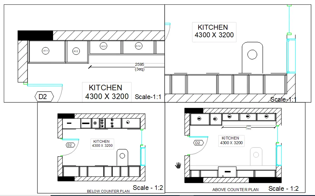
- Go to model space in layout
- Click inside of bottom left viewport
- Type v and press enter
- Click on ‘Above contour plan’ and click on set current
- Change the scale to 1:2
- Click inside of bottom bottom viewport
- Type v and press enter
- Click on ‘Below contour plan’ and click on set current
RESULT-
LINK-https://web.autocad.com/acad/me/sid/shares/drawings/e32bbf15-c3fb-47b2-99fb-3a27f4602102/editor
3.CREATE A LAYOUT OF THE SECTION OF INDUSTRY (CHALLENGES-9)
https://web.autocad.com/acad/me/sid/shares/drawings/b6995439-3790-4ab0-b9b6-8b916f7452f6/editor
PROCEDURE-
Go to layout tab and delete the current viewports available
- Right click on the layout tab
- Click on rename and type ‘Industrial Building layout’
- Go to Page setup manager
- Click on new
- Set name as A4
- Change printer to AutoCAD PDF
- Set paper size as ISO full bleed A4
- Change plot area to ‘Layout’
- Click okay
- Go to model tab
Type ‘v’ and press enter
- Click on new
- Type name as ‘Industrial Building’
- Click on define window
- Select the entire drawing to fit
- Click on new
- Type name as ‘Manhole’
- Click on define window
- Select the area around the manhole
- Click on new
- Type name as ‘Duct and sprinkler’
- Click on define window
- Select the area around the middle sprinkler and right duct
Plotting
Type plot and press enter or select plot from the menu bar
- Set name as Industrial_Building_Layout
- Change printer to AutoCAD PDF
- Set paper size as ISO full bleed A4.
- Change plot area to ‘Layout’
- Change plot style table to ‘monochrome.ctb’
- Check the preview for adjustments
- Click ok to plot
- Select the path and set name
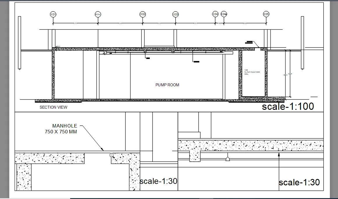
RESULT-
LINK- https://web.autocad.com/acad/me/sid/shares/drawings/b6995439-3790-4ab0-b9b6-8b916f7452f6/editor