Creating 3D Isometric view of various structural elements in AutoCAD
1. Create a 3D Isometric View of the building with plan and elevation given.
AIM:
To create a 3D Isometric View of the building with plan and elevation.
USED TOOLS:
LINE
RECTANGLE
OFFSET
LAYERS
EXTRUDE
3DROTATE
3DORBIT
SUBTRACT
MATERIAL ASSIGNING
VIEW
DIMENSIONS
TEXT
PROCEDURE:
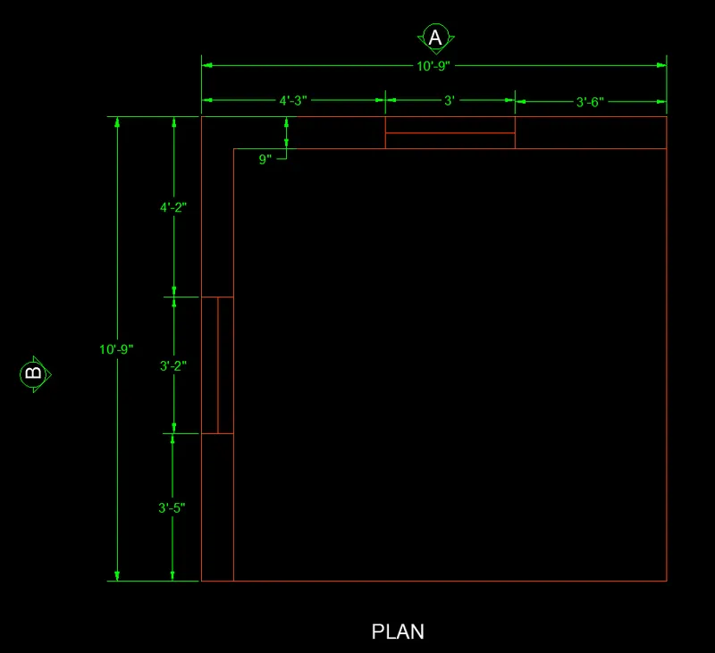
Creating the plan with a dimension of 10'-9" X 10'-9"
Explode the plan and offset the wall at two sides with a 9" thickness
Create the window with 3' X 9" width at Elevation A side, and 3'-2" X 9" width at Elevation B side
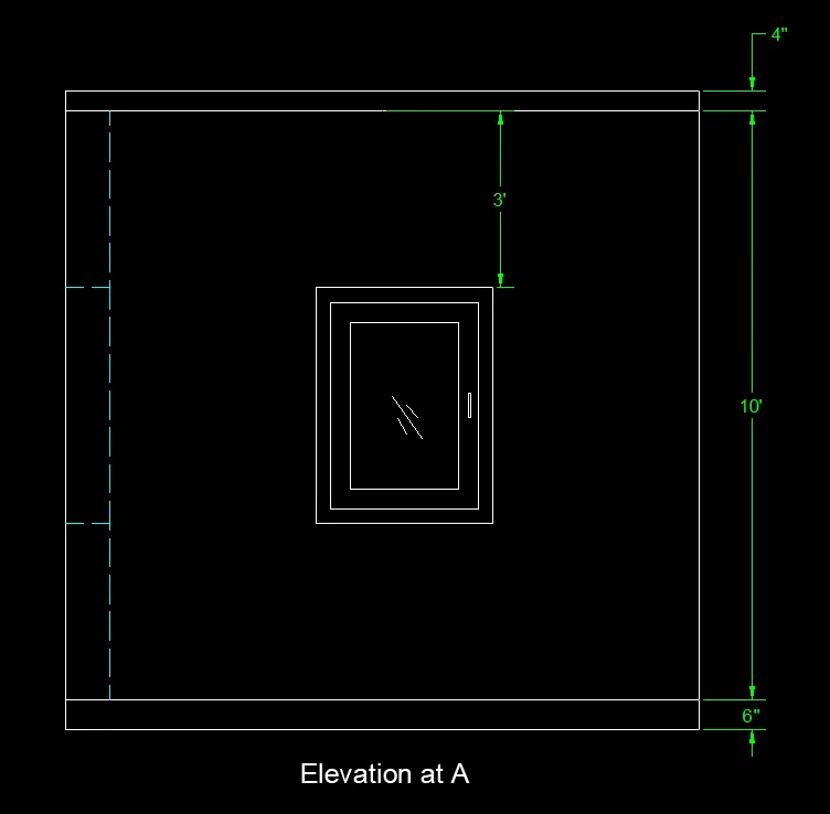
Creating the ELEVATION-A
Extending the lines from the plan with Xline Tool
Draw one horizontal line 10'-9" perpendicular to the Xline
Offset the line 6" for the slab, 10' for building height & 4" for substructure
Draw a window:
offset a 3' line from top and bottom then create one rectangle with 4'X3'
Offset the rectangle 3" inside again offset 4".
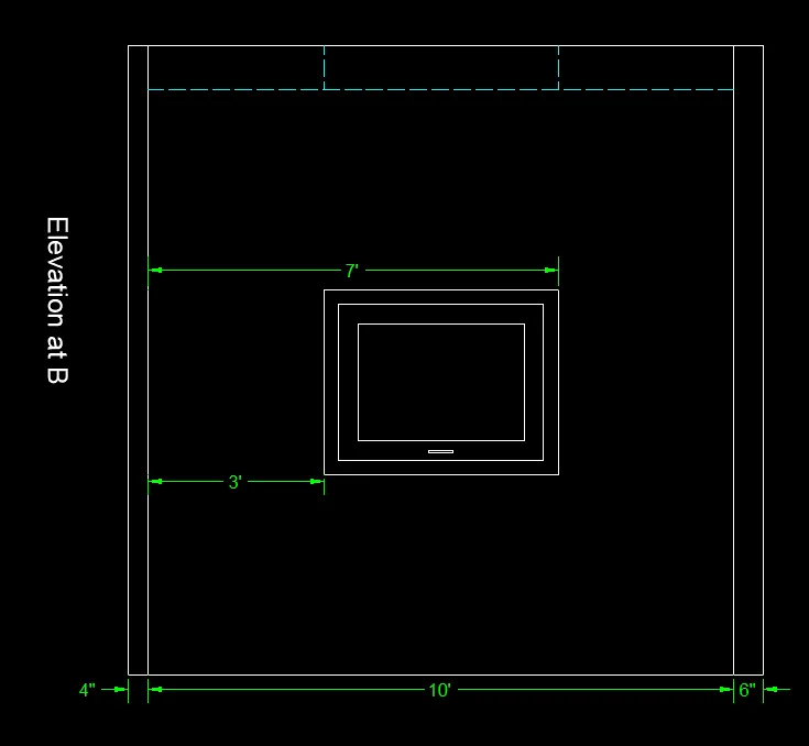
Creating the ELEVATION-B
Extending the lines from the plan with Xline Tool
Draw one vertical line 10'-9" perpendicular to the Xline
Offset the line 6" for the slab, 10' for building height & 4" for substructure
Draw a window:
offset a 3' line from top and bottom then create one rectangle with 4'X3'-2"
Offset the rectangle 3" inside again offset 4".
CREATING THE 3D ISOMETRIC VIEW:
Change the view cube direction from Top to the S-W direction.
BOUNDARY CREATION:
COMMAND: BO>
Select the boundary line of the walls for creating the Region of the object
EXTRUDE:
COMMAND: EXT>
Extrude the walls up to 10' height.
Extrude the 4" flooring at the downside.
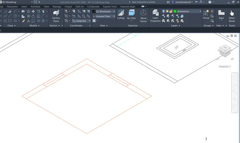
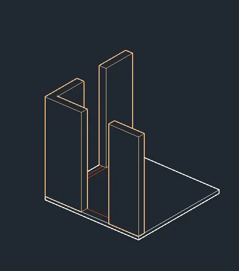
ISOMETRIC VIEW EXTRUDING OBJECT
Set the UCS at the top face of the window and Extrude the wall up to 3' height>
Then Set the UCS at the top face of the wall and create one rectangle with the size of the window.
Extrude the rectangle with a 3' downwards.
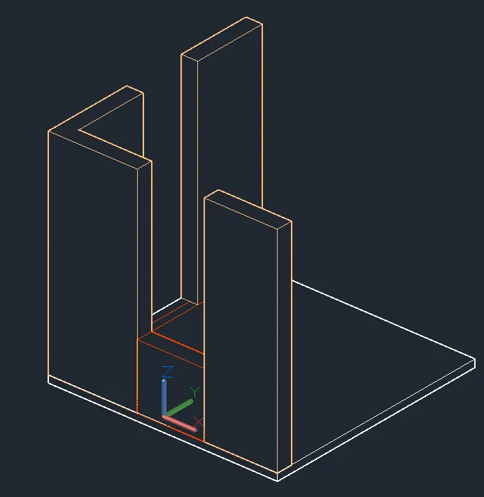
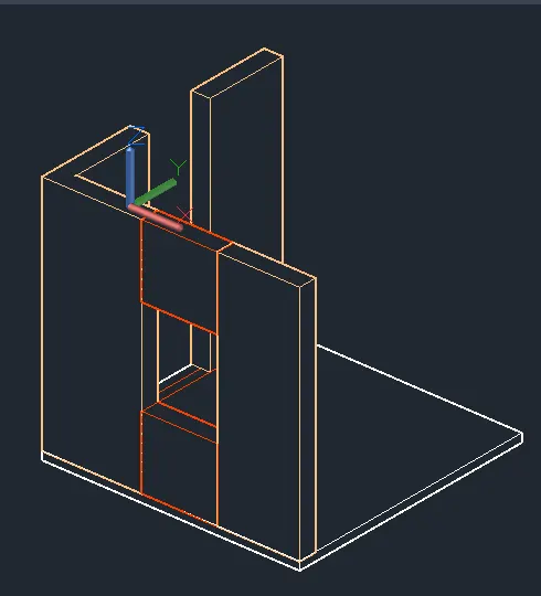
WALL UP TO SILL LEVEL WALL ABOVE WINDOW HEAD
UNION:
Union makes the two different regions into a single region.
Command: UNI>
Select the objects which one is makes union.
3D ROTATE:
Rotating the 2D elevation into a 3D and copying the object and place at 3D Object.
Command: 3DR>
select the base point and select the Axis of rotation then specify the angle of rotation.
Then copied that object and placed it in a 3D wall.
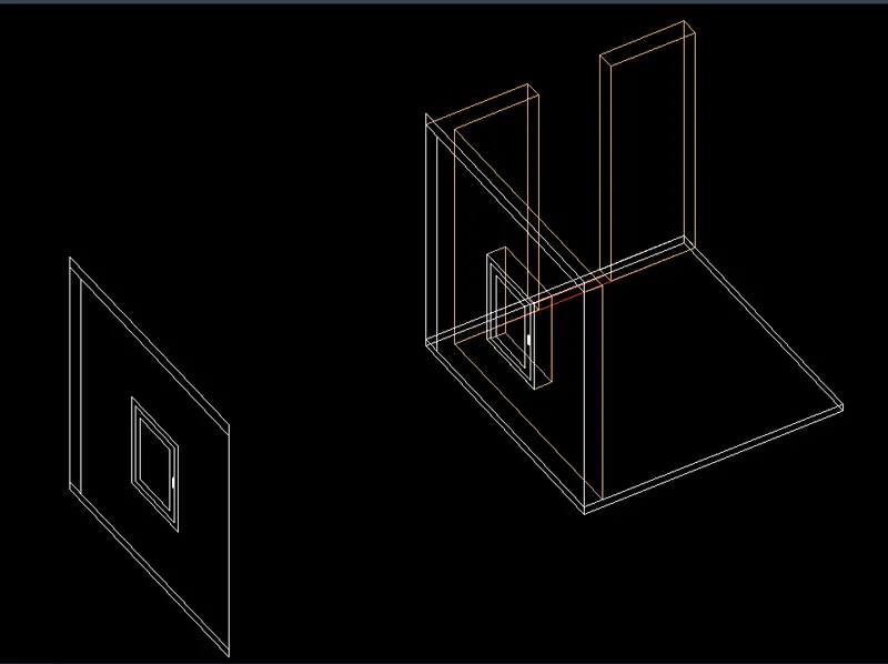
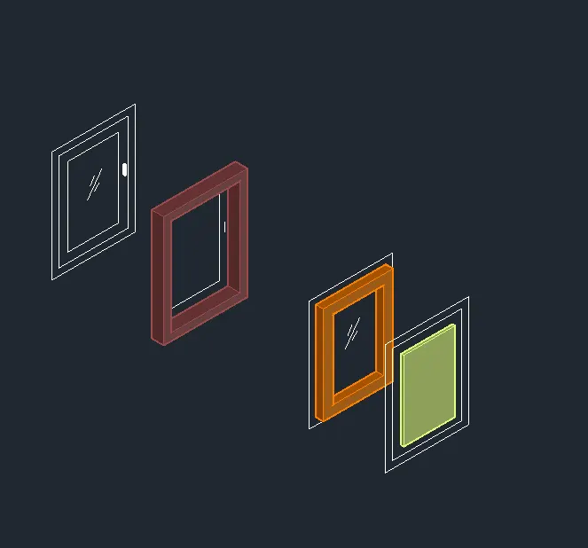
Creating the 3D window FRAME:
EXtrude the Frame 5" thickness and extrude the mullion with 5" thickness
Subtract:
Command: sub>
select the frame press enter, then select the mullion press enter>
The frame will be created.
Creating the 3D window Mullion:
EXtrude the Mullion 3" thickness and extrude the panel with 3" thickness
Subtract:
Command: sub>
select the Mullion press enter, then select the panel press enter>
The mullion will be created.
Creating the 3D window PANEL:
EXtrude the panel 0.5" thickness.
Copied the 3D window frames and Placed them at their places.
Assigning Selected material to Object:
Invoking the tool:
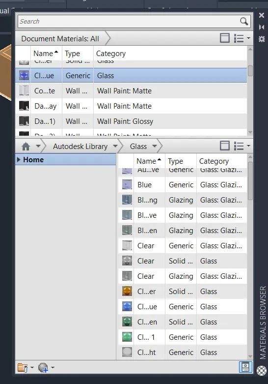
Visualization > material > material browser
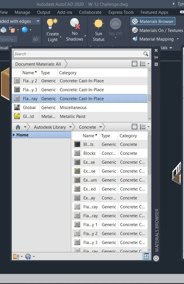
select the Materials from the AutoDesk library and send them up in the document material by selecting the arrow symbol.
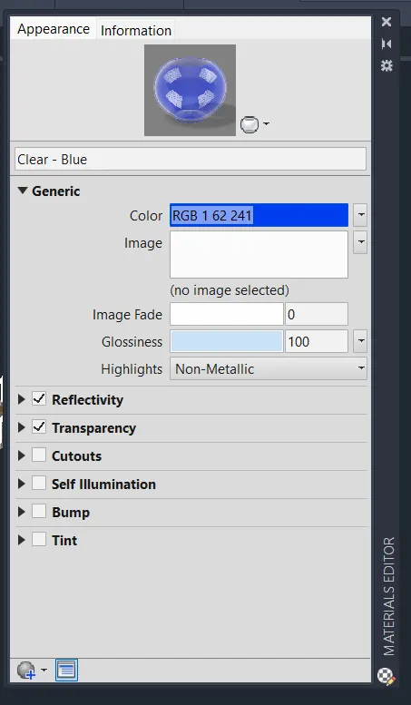
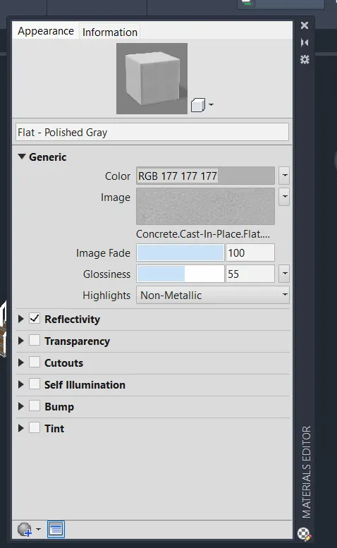
Duble click the selected material, Appearance information dialogue box will open, here we can edit the color, Finishing, application, etc.,
Assigning the material to the object:
select the object to assign material
select the material which one is assigning and right-click the mouse then select the "Assign to selection"
Change the visual style for better looking.
RESULT:
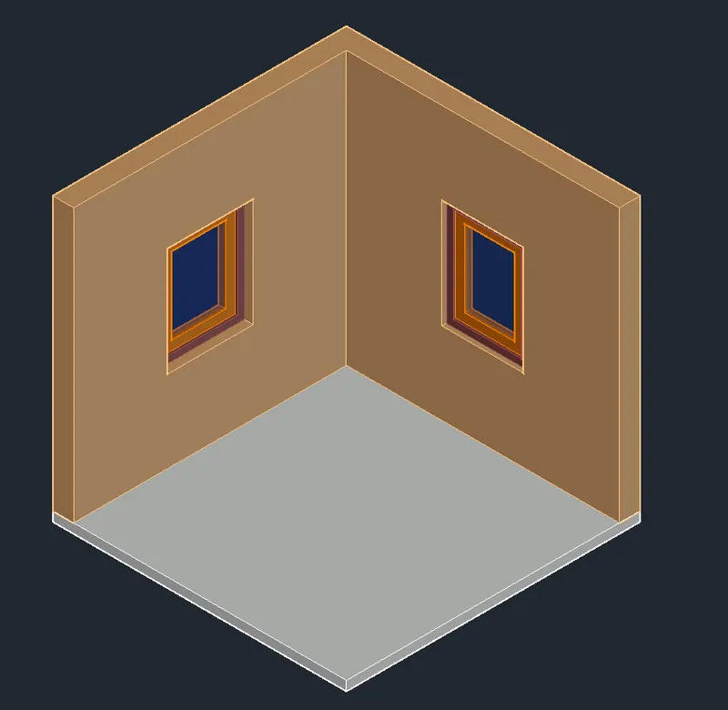
Creating the 3D Isometric view of the Building with Plan, Elevation, other Commands, and Tools.
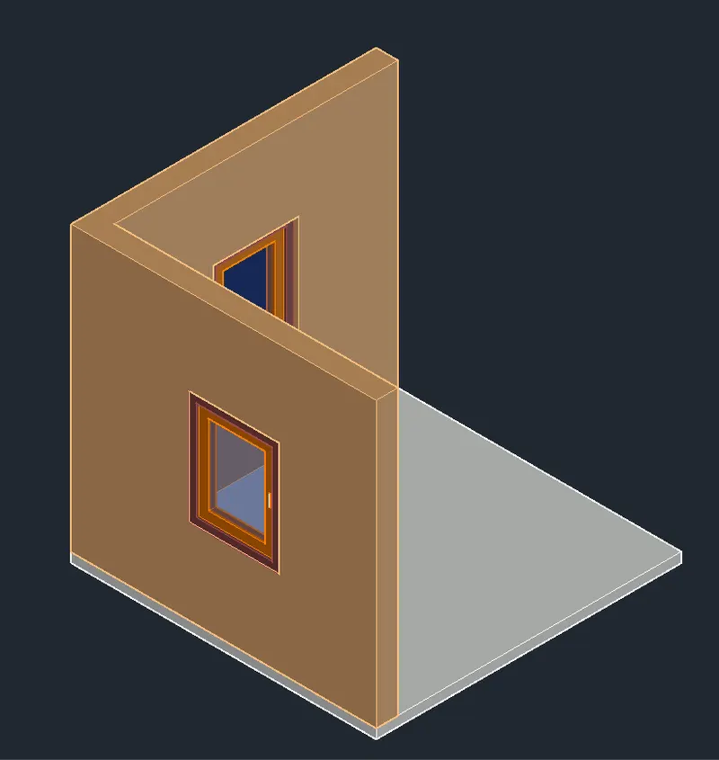
S-W DIRECTION
S-E DIRECTION
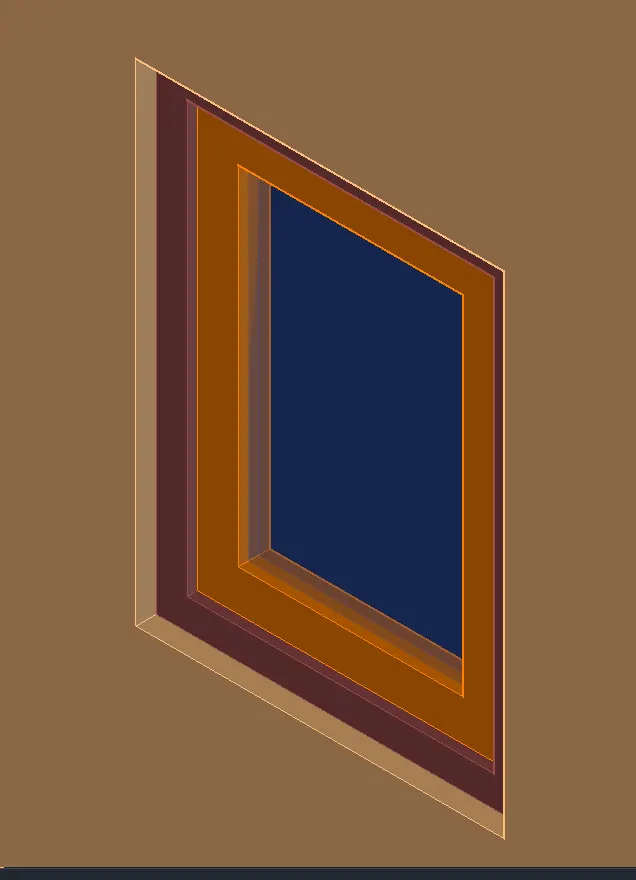
WINDOW
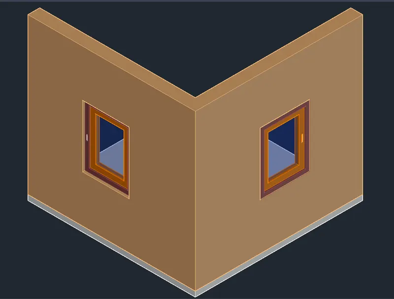
N-W DIRECTION
2. Create the 3D View of the Building Façade as given in the plan and elevation. Also, see the detail of the window.
AIM:
To create the 3D View of the Building by using plan and elevation.
USED TOOLS:
LINE
RECTANGLE
OFFSET
LAYERS
EXTRUDE
3DROTATE
3DORBIT
SUBTRACT
MATERIAL ASSIGNING
VIEW
DIMENSIONS
TEXT
PROCEDURE:
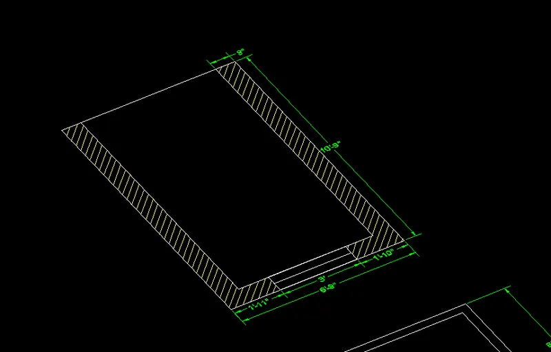
Creating the plan with a dimension of 10'-9" X 6'-9"
Offset the wall width as 9"
Trim all extended lines
Create the window with 3' X 9".
BOUNDARY CREATION:
Creating the Boundary of the plan for extruding the plan.
Command: BO>
Select the internal point of the wall >
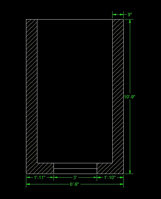
PLAN
Create the Elevation by extending the lines and drawing one horizontal line 6'-9" which is perpendicular to the Xline
Offset the Horizontal line by the dimension that is given in reference elevation.
creating the window with a dimension of 3'X4'
Offset the 2" for the window frame, 3" for the window mullion, and create a window panel by creating a rectangle on both sides.
At top of the building creating the frame with the dimension of 4"X9"
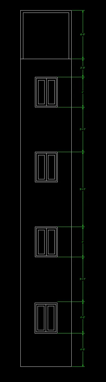
ELEVATION
Creating the 3D view of the building:
Change the view to isometric for creating the 3D objects.
EXTRUDE:
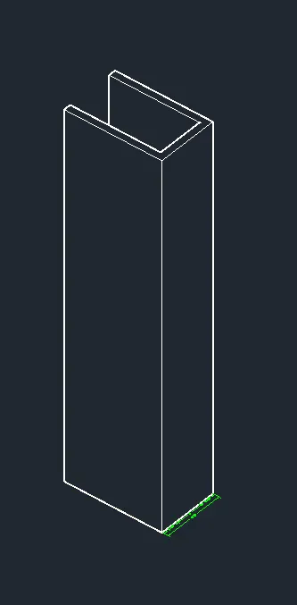
Command: EXT>
Select the boundary line which we created and press enter to start to extrude
Extrude the walls up to the 40'-9".
3D ROTATE:
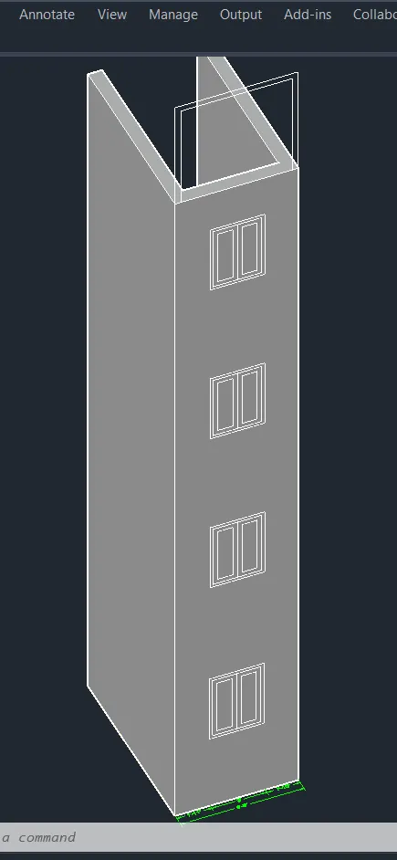
Rotate the elevation and place it in the 3D object for creating the windows and top projection
Command: 3DR>
EXTRUDE:
Extrude the window frame
Command: EXT>
Select the window frame line and extrude it inside
SUBTRACT:
COMMAND: SUB>
Select the 3D object and press enter
then select the 3D window frame region press enter>
similar to all other 3D objects for subtracting.
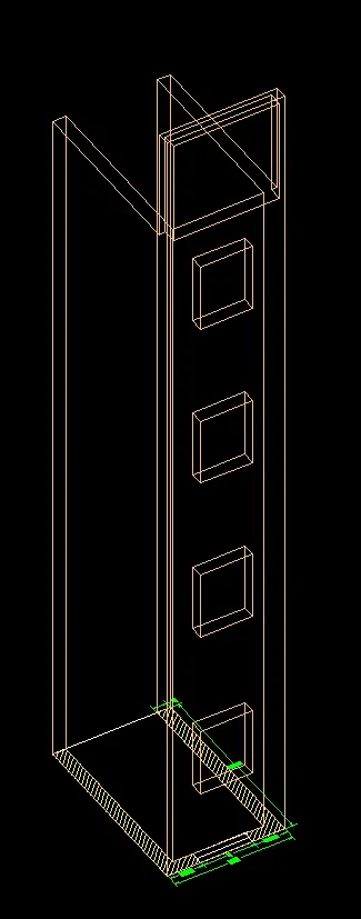
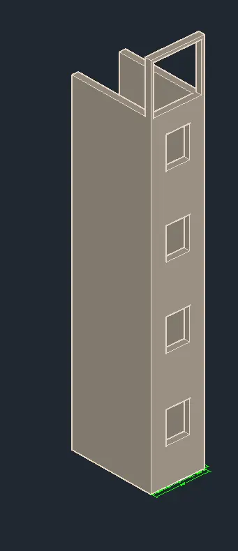
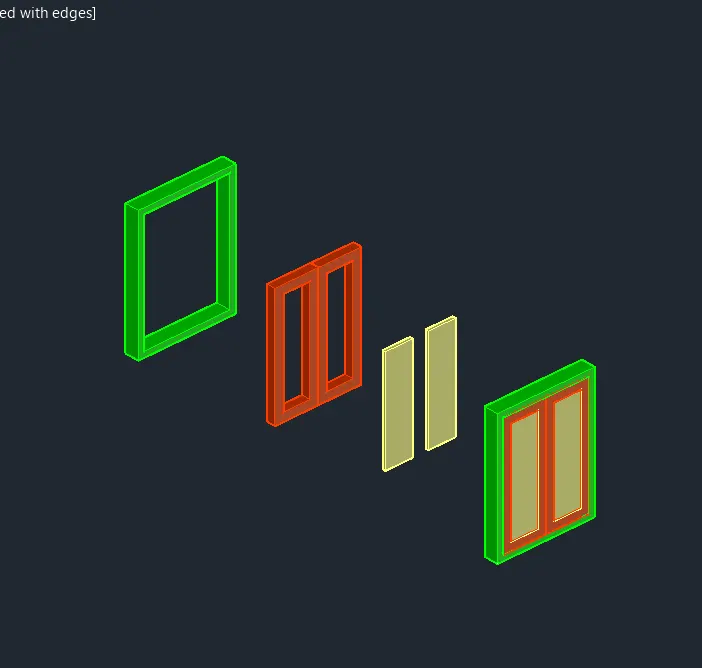
Creating the 3D window.
EXTRUDE:
Extrude the window frame, window mullion, and window panel
Command: EXT>
Select the window frame line and extrude it inside
select the window mullion line and extrude it inside
select the window panel and extrude inside.
After creating the 3D window Placed at their respective places.
Assigning Selected material to Object:
Invoking the tool:
Visualization > material > material browser
select the Materials from the AutoDesk library and send them up in the document material by selecting the arrow symbol.
Duble click the selected material, Appearance information dialogue box will open, here we can edit the color, Finishing, application, etc.,
Assigning the material to the object:
select the object to assign material
select the material which one is assigning and right-click the mouse then select the "Assign to selection"
RESULT:
Creating the 3D elevation of the given plan, by using various commands and tools.
3D ELEVATION:
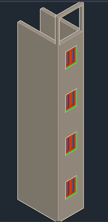
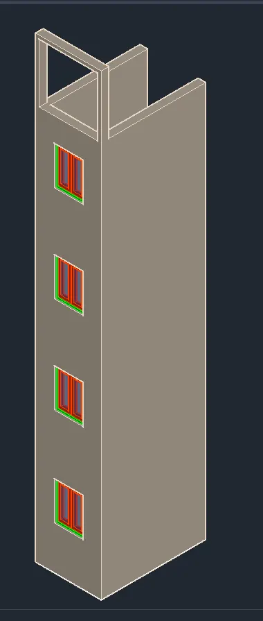
S-W DIRECTION S-E DIRECTION
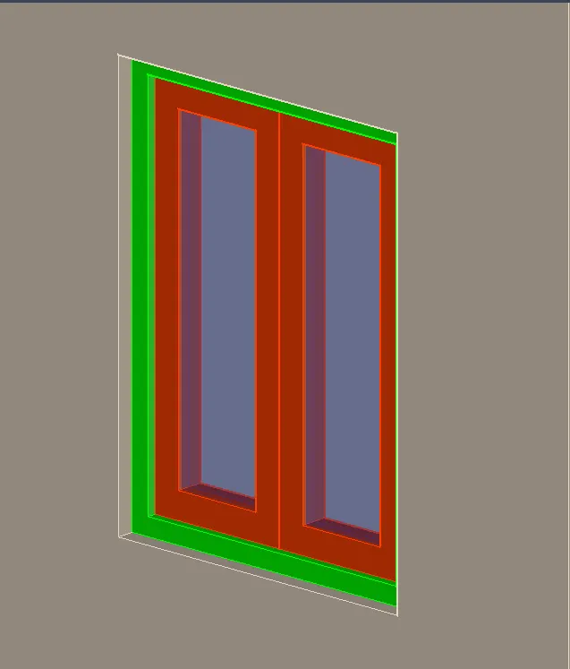
WINDOW
3. Create the isometric 3d view of a stair with a railing as shown in the plan and elevation. Assume the size of the balustrades and the handrails.
AIM:
To create the isometric 3D view of a staircase with a railing as shown in the plan and elevation.
USED TOOLS:
LINE
RECTANGLE
OFFSET
LAYERS
EXTRUDE
3DROTATE
3DORBIT
SUBTRACT
MATERIAL ASSIGNING
VIEW
DIMENSIONS
TEXT
PROCEDURE:
Create the plan of the staircase win a dimension of 4'X12'
Explode the created plan and offset both sides with dimensions of 2" and offset the Tread 1'
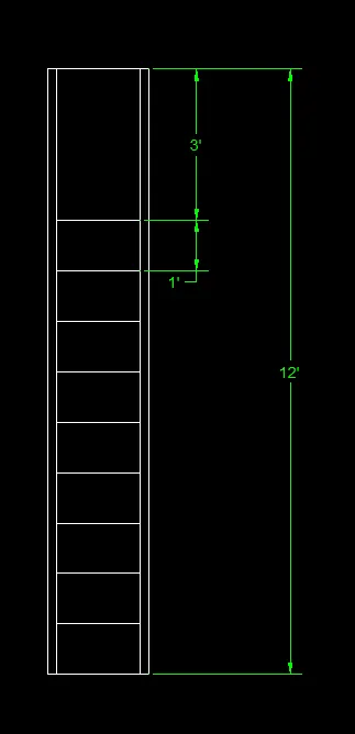
Creating the SIDE ELEVATION of the staircase:
Changing the view cube FRONT side and creating the side elevation of a staircase in the X-Z plane by using the LINE command.
EXTRUDE:
Command: EXT>
After creating the Side elevation of the Staircase, change the view cube into the S-W direction and
SET OF UCS:
Command: UCS>
Set the UCS on the side elevation face of the staircase. Then create the Boundary for Region it.
Then extrude the object 4' in the Y-Axis direction.
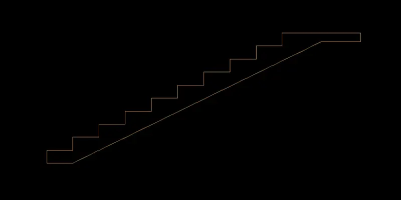
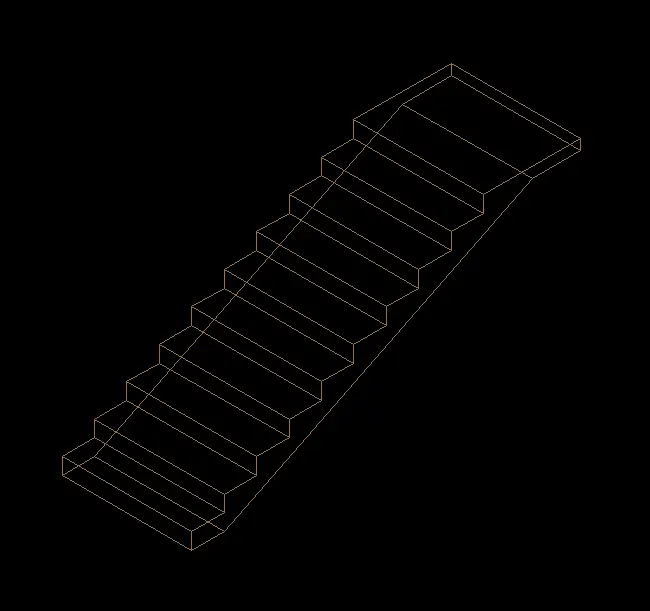
Side Elevation After Extruding the Stairs
Creating the Balustrades:
Set the UCS at the top face of the Stair and Create one circle with a radius of 1".
Copy the circles on all stairs.
select all circles and extrude the circle with a height of 3'-2" >
select all balustrades and Offset them by selecting the center point of the staircase.
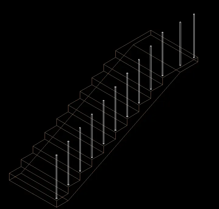
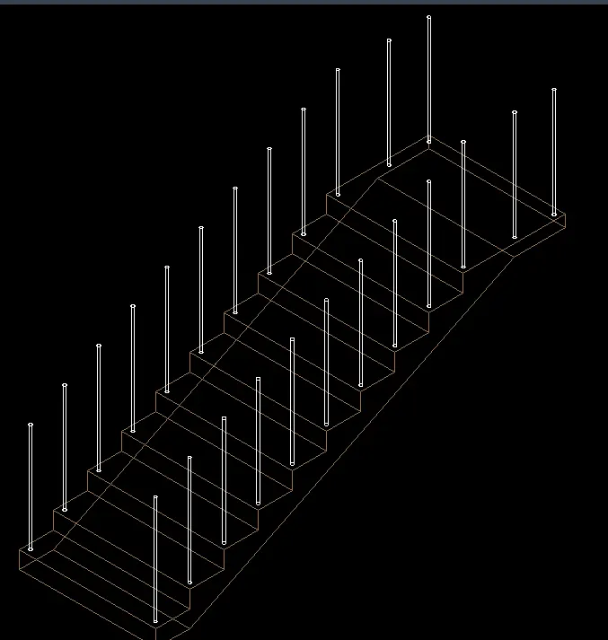
Creating Balustrades Balustrades at Both sides
Creating the Handrail on the Balustrades:
Draw one line by selecting the first point on the first balustrade center point then select the top balustrade center point, line continues to the last balustrade.
Create one circle on the first balustrade with a radius of 1" then,
EXTRUDE:
command: EXT>
select the circle for extruding, then choose the PATH option for extruding the circle with created path.
A handrail will be created on both sides.
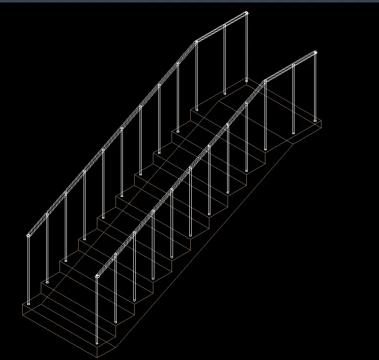
Staircase with Handrails
Assigning Selected material to Object:
Invoking the tool:
Visualization > material > material browser
select the Materials from the AutoDesk library and send them up in the document material by selecting the arrow symbol.
Duble click the selected material, Appearance information dialogue box will open, here we can edit the color, Finishing, application, etc.,
Assigning the material to the object:
select the object to assign material
select the material which one is assigning and right-click the mouse then select the "Assign to selection"
RESULT:
Creating the 3D view of the Staircase by using the plan, Side Elevation, and various Commands and Tools.
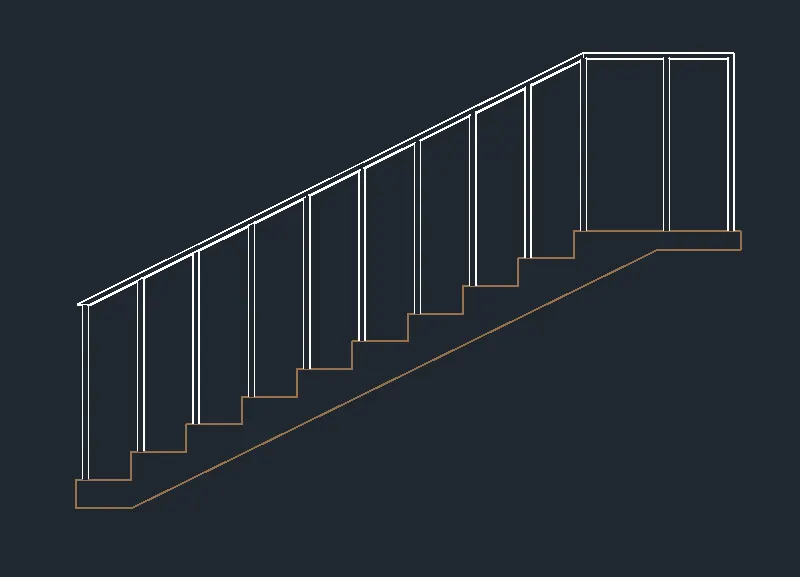
SIDE ELEVATION
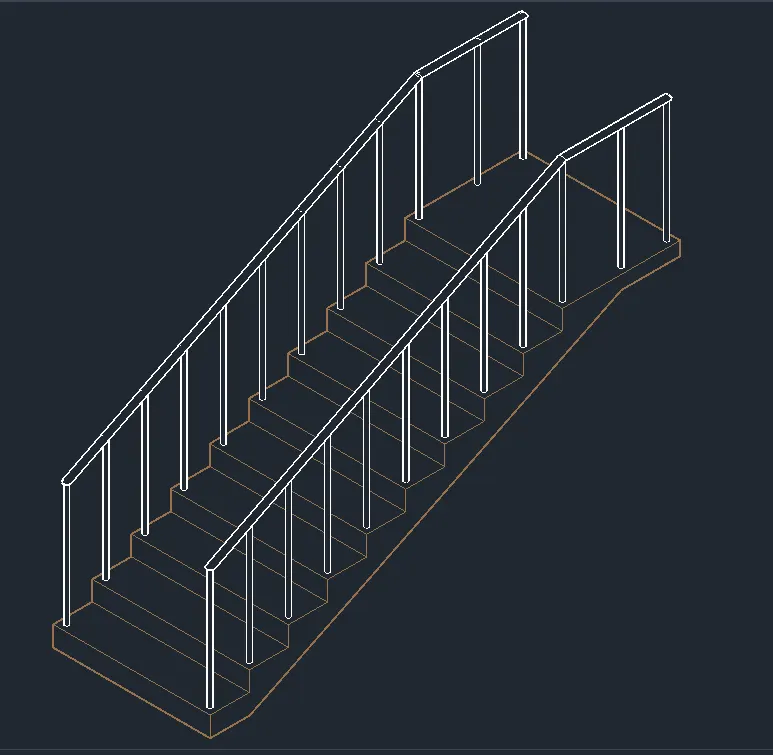
S-W DIRECTION
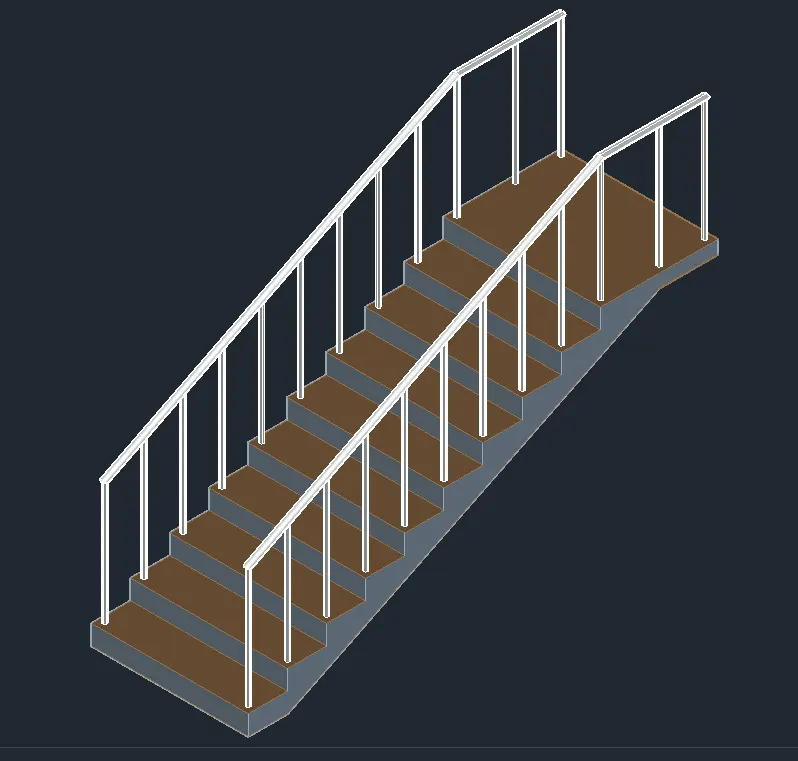
S-W ELEVATION
4. Create the 3D view of a Wall with spread footing. Create the Door opening only. Assume the size of the parapet and the coping. See the plans and elevation for the details. Also, create a rendered view of the model with materials of your choice.
AIM:
To create the 3D view of a Wall with spread footing.
USED TOOLS:
LINE
RECTANGLE
OFFSET
LAYERS
EXTRUDE
3DROTATE
3DORBIT
SUBTRACT
MATERIAL ASSIGNING
VIEW
DIMENSIONS
TEXT
PROCEDURE:
Creating the plan with the given dimension as 900mm X 7500mm
Explode the created rectangle and offset both sides with 150mm insides.
Offset the line with 100mm on both sides.
Once again offset the lines with 85mm on both sides.
Offset the Horizontal line with 3300mm from both endpoints.
Creating the Door:
Creating the Frame of the Door with a dimension of 30mm, and Door swing will be created by using the Circle tool,
Trim all the extended line over the swing.
Drawn the sunshade projection with of 450mm,
HATCH:
Creating the Hatch:
Command: H>
Both longitudinal sides hatch with Concrete Patterns for describing the PCC on Footing.
Hatching the Wall pattern at the center portion of the plan.
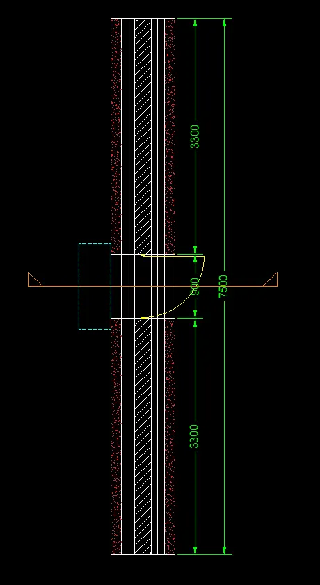
PLAN
Creating the Section of Wall Footing:
Projecting the vertical X lines from the Plan, draw one horizontal line with 900mm, then
Offset the Horizontal line with 300mm PCC of foundation will be created, trim the X lines of PCC
Offset the PCC line with 400mm, for creating the first step of footing
Offset the 400mm for the second step of footing
Offset the 600mm up to floor level,
Offset the building height up to 3300mm, and create the sunshade bottom level 2100 from FFL, drawing the projection as per given dimensions.
Parapet wall height is taken as 900mm and coping 150mm
Trim all extended and X lines over the section.
HATCH:
Hatching the section with ANSI31 pattern as shown in the figure, and concrete pattern assigns to the PCC portion.
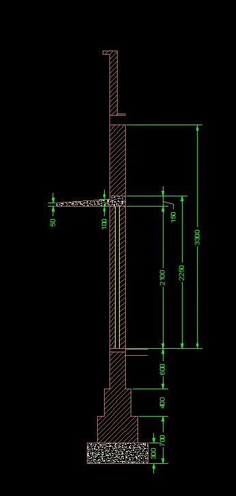
SECTION OF WALL FOOTING
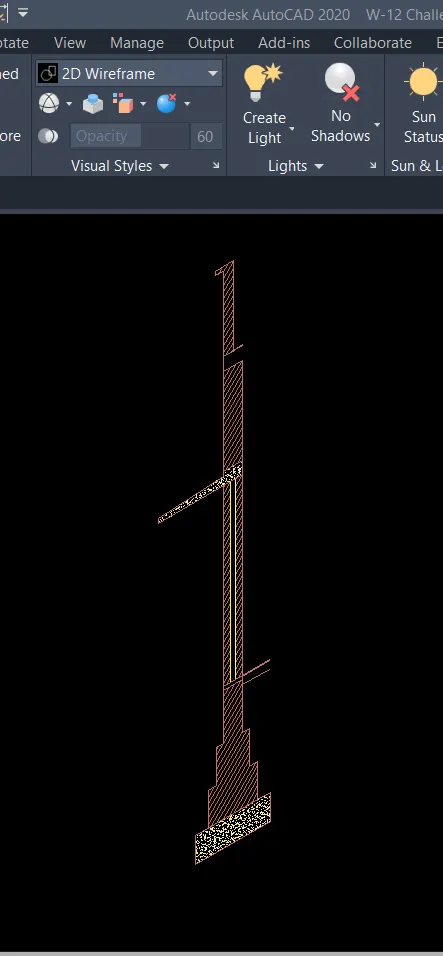
CREATING THE 3D VIEW:
Changing the view cube in the S-W direction
Change the visual style as 2D wireframe
Rotate the section in the Z-Axis direction.
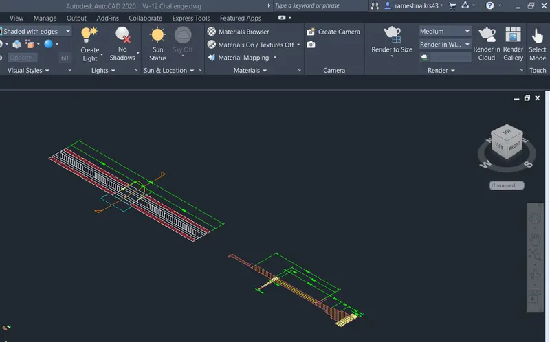
3DROTATE:
Command: 3DR>
select the object to rotate
select the base point of the object for rotation
select the axis of rotation
specify the direction to rotate or enter the angle of rotation.
Boundary creation:
Creating the boundary for making the Region it.
Command: BO>
select all the boundaries press enter
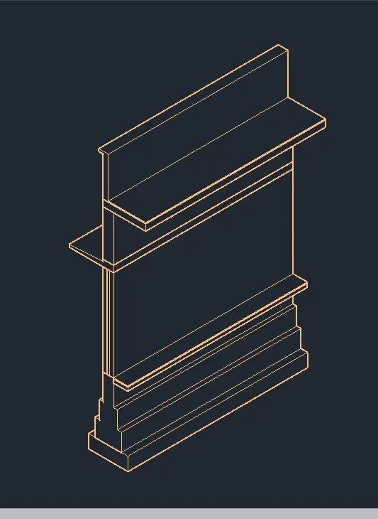
EXTRUDE:
Change the view cube in the S-E direction, and Extrude the section in the Y-Axis direction,
Invoking the tool:
Command: EXT>
select all the boundaries and press enter to start the extruding, extrude in Y-Axis direction.
Assigning Selected material to Object:
Invoking the tool:
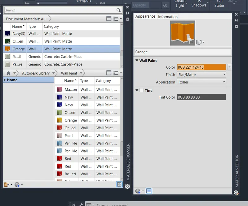
Visualization > material > material browser
select the Materials from the AutoDesk library and send them up in the document material by selecting the arrow symbol.
Duble click the selected material, Appearance information dialogue box will open, here we can edit the color, Finishing, application, etc.,
Assigning the material to the object:
select the object to assign material
select the material which one is assigning and right-click the mouse then select the "Assign to selection"
RESULT:
Creating the 3D view of a wall with spread footing by using various Commands and Tools.
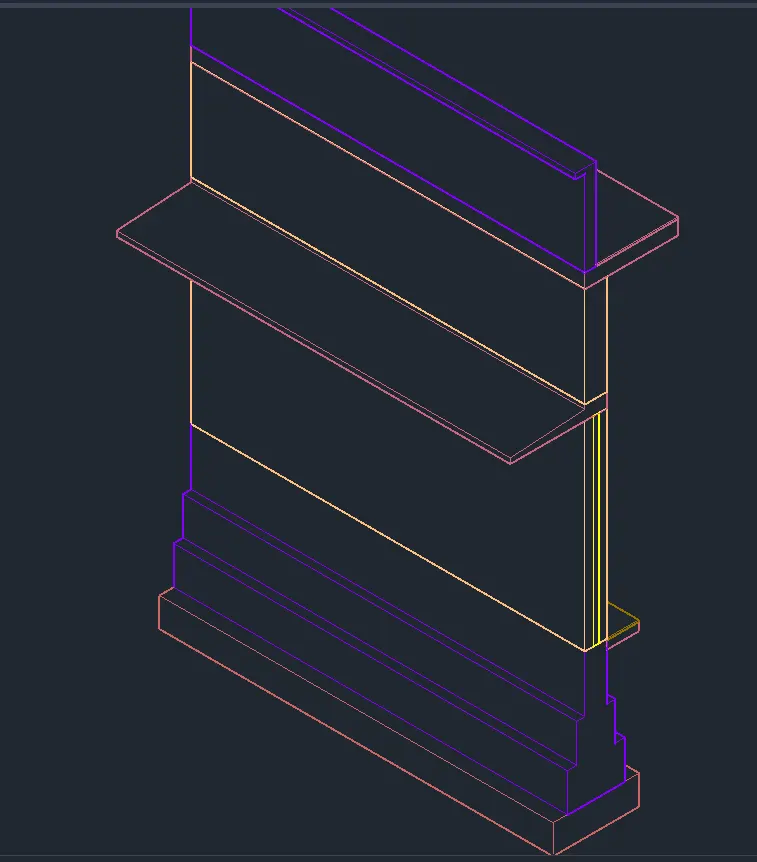
S-W ELEVATION in Hiding mode
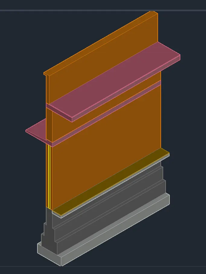
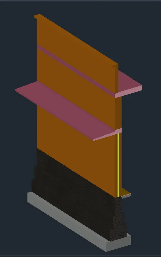
S-E ELEVATION in Shade mode S-W ELEVATION in Realistic mode