Creating 3D Isometric view of various structural elements in AutoCAD
Creating 3D Isometric view of various structural elements in AutoCAD
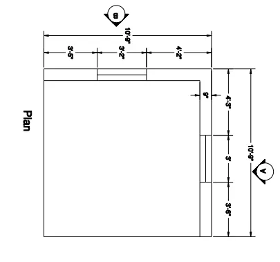
1.Create a 3D Isometric View of the building with plan and elevation given.
AIM:-
Using Autocad, create a 3D isometric image of the building that includes the plan and elevation.
PROCEDURE:-
- Type units >engineering>0'-0" at the command prompt.
- Enter limmax>100',100' at the command prompt.
- Enter limits >0',0' on the command prompt.
- Enter zoom > an at the command prompt.
- Access the upper view.
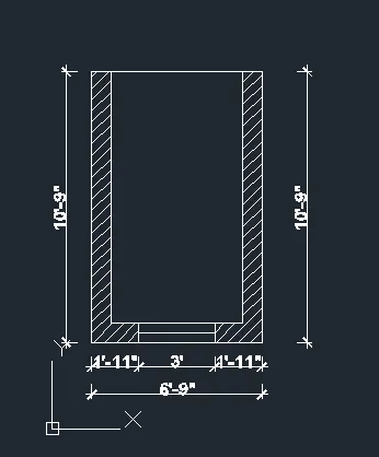
- Type "l" at the command prompt to draw lines with a thickness of 9" and a distance of 10'-9" and 3',3-2".
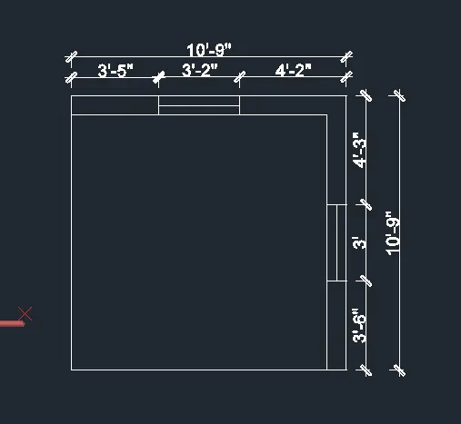
- Now using rectangle command draw the rectangles in the wall.
- then extrude the walls
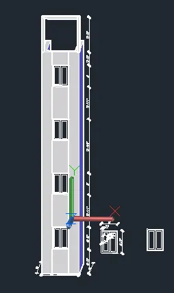
- then create the windows as size mention
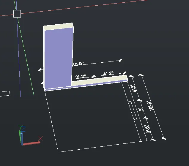
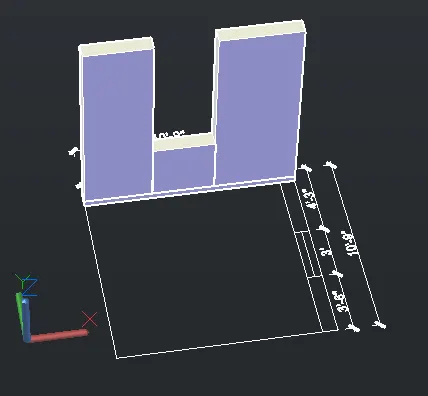
- now create the elevation A & B
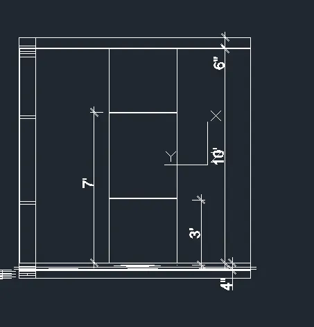
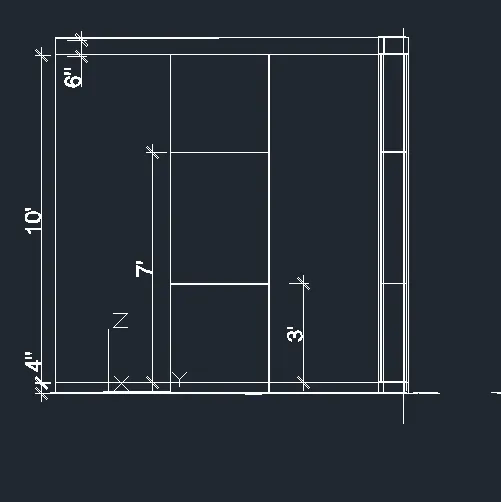
2. Create the 3D View of the Building Façade as given in the plan and elevation. Also, see the detail of the window.
- 1st create the 2D plan in autocad application using line, rectangel, trim, extend etc. drafting tools
- then extrude the poly lines upto the desire length.
- then using sustructe command create the windows details.
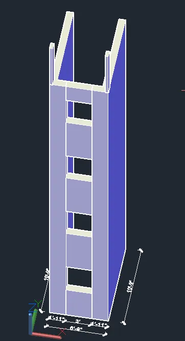
Result:-
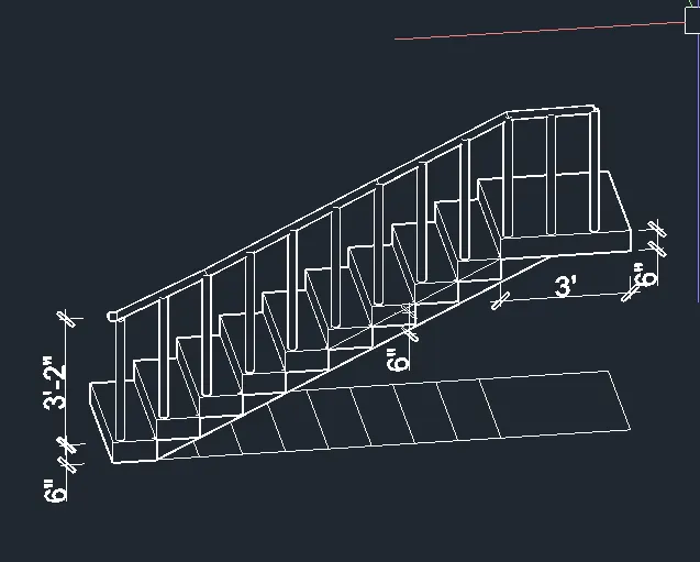
3. Create the ismoteric 3d view of a stair with railing as shown in the plan and elevation. Assume the size of the balustrades and the hand rails.
- 1st create the 2D plan in autocad application using line, rectangel, trim, extend etc. drafting tools
- then create a rectangal of the stair size.
- then extrude the rectangle upto riser size(6") then copy the staire above another.
- then create the hand rail.hight of 1000 mm(3'-4").
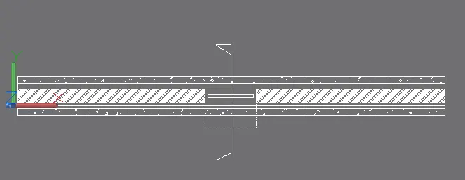
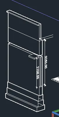
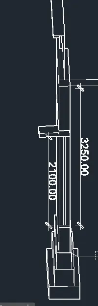
4. Create the 3D view of a Wall with spread footing . Create the Door opening only. Assume the size of the parpaet and the coping. See the plans and elevation for the details. Also, create a rendered view of the model with materials as of your choice.