Creating 3D Isometric view of various structural elements in AutoCAD
AIM :
CREATING ISOMETRIC VIEW OF VARIOUS STUCTURAL ELEMENT USING AUTO CAD
COMMANDS USED :
LINE
CIRCLE
RECTANGLE
TRIM
COPY
EXPLODE
EXTRUDE
UCS
SWEEP
CAMERA
SUBTRACT
DIMLINEAR
BOUNDARY
3DORBIT
REGION
1.
AIM :
TO DRAW 3D ISOMETRIC VIEW OF BUILDING.
PROCEDURE :
Open autocad
Units:engineering
COMMAND:layer properties
Create layers by cliking new layer
Change the current layer to 3D WALL
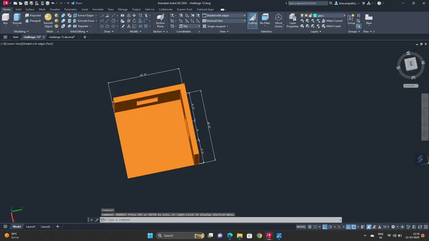
create a rectangle of dimension 10'9''x10'9''
Offset the rectangle 9'' as wall thickness
Delete the left bottom line and extend them to edges 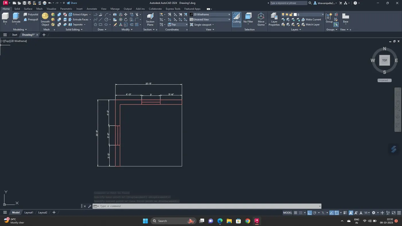
CREATING A 3D VIEW
Change the view to 3d by clicking view cube
Create the boundaries for the walls using BO command
Extrude the boundaries created to total height of 10'10''
draw a rectangle at both windows and create boundaries
Extrude them as walls
By union command join all the walls ans windows
Move the rectangle upto a height of 3'4''
Create region
Extrude the rectangle as window height 4'
Now using SUBTRACT command subtract the window from the walls
Creating a window
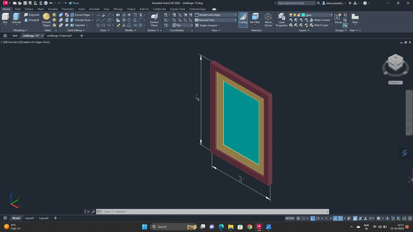
Draw a rectangle of dimension 3'x4'
Offest the rectangle by the distance of 3''
Offest the rectangle by the distance of 4''
Create boundary
BY Subtract command create the frame
select the bigger region and then smaller regions to subtract them
create frame,mulion and glass by the same process
Extrude them .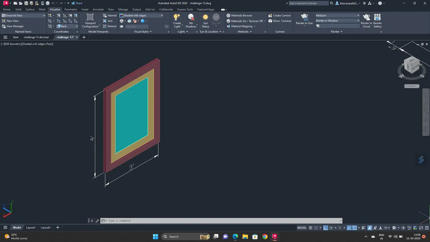
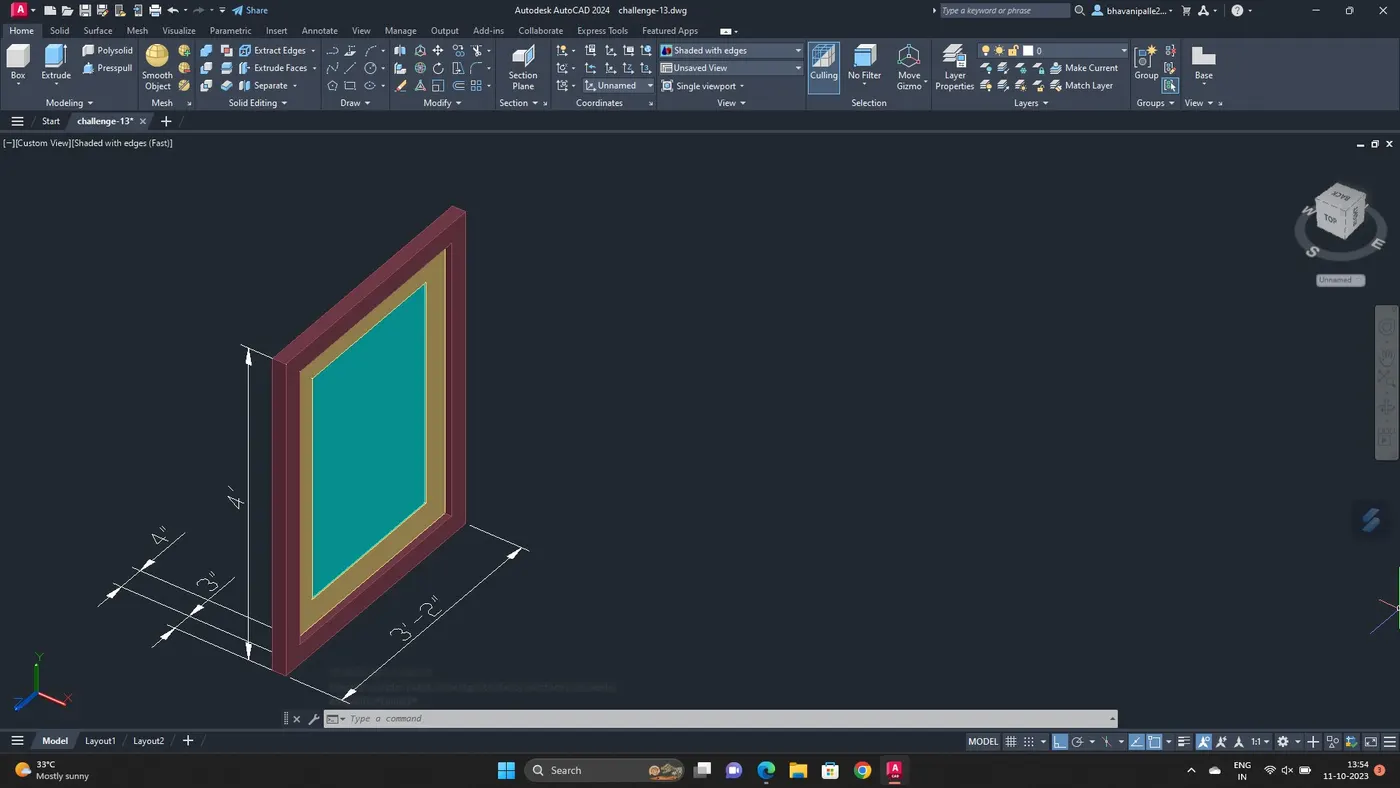
Create another window by taking rectangle with dimesion3'2''x4'
Offset the rectangle by distance 3''
Offset the rectangle by distance 4''
Create boundry
Subtract command
Select bigger region and then smaller region for subtracting
Create frame,mullion,glass by the same process
Go to visualize command
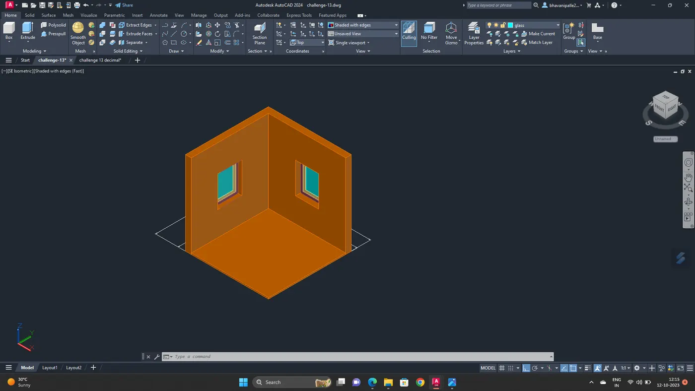
Create nwe views and save them
View 1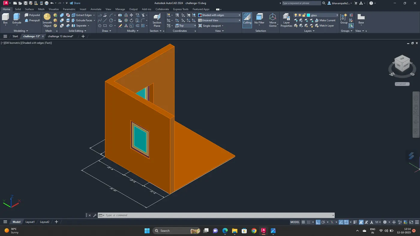
2.
AIM :
To draw the 3D Building facade as given
PROCEDURE :
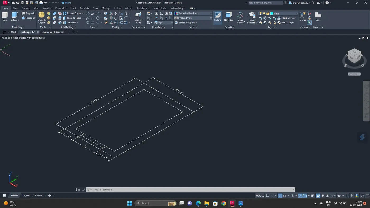
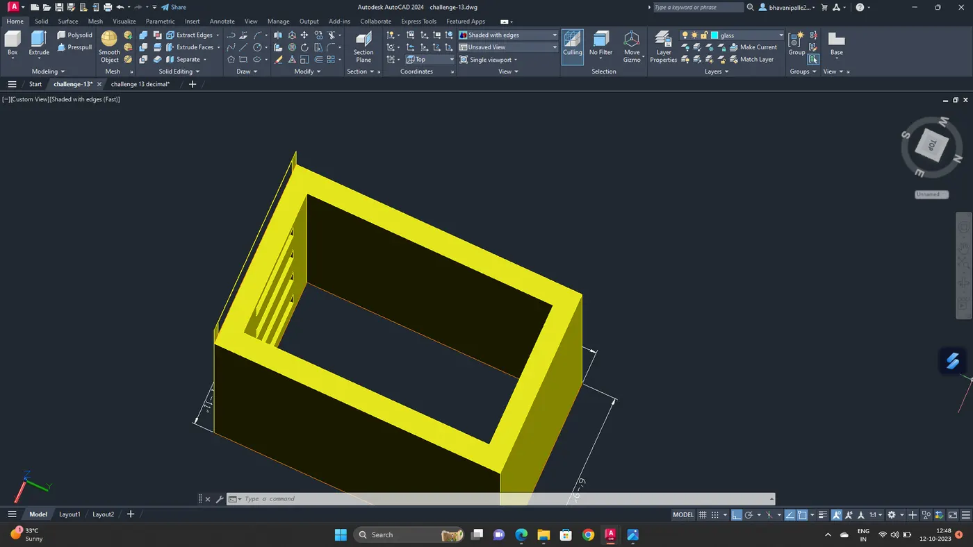
Create a rectangle of dimesion 6'9''x10'9''
Offest the rectangle with distance of 9''
Create window opening of dimesion 3'
Change the view to 3d
Create boundaries for walls and windows
Extrude the boundaries 10'10'
Move the rectangle and create region
Extrude the regfion to 4'2''
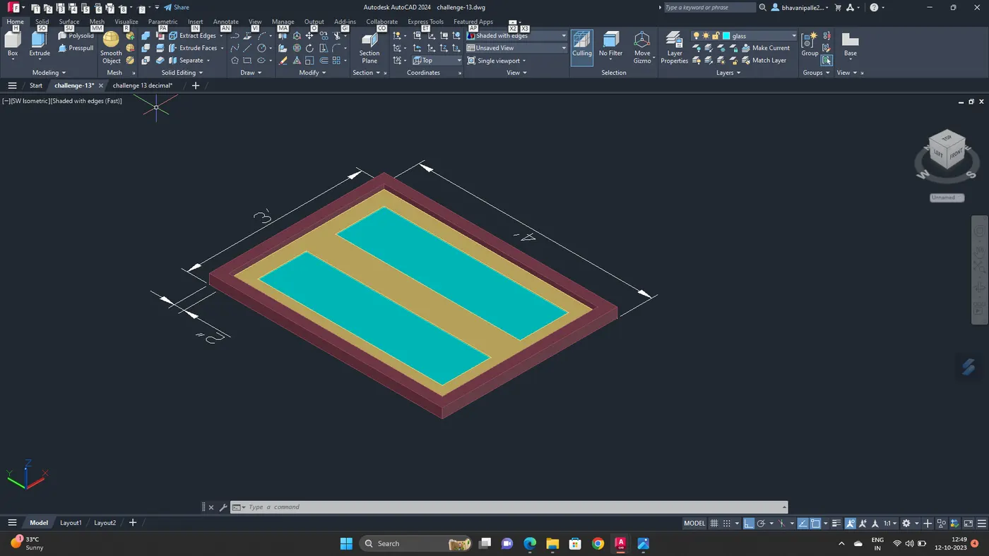
Creating window frame
Draw rectangle of 3'x4'
Offset the rectangle with distance3''
Offset the rectangle with distance4''
Draw a line connecting midpoints
Trim unnecessary lines
Create boundaries
BY Subtract command create the frame
select the bigger region and then smaller regions to subtract them
create frame,mulion and glass by the same process
Extrude them
The window created is placed at its position
group all items
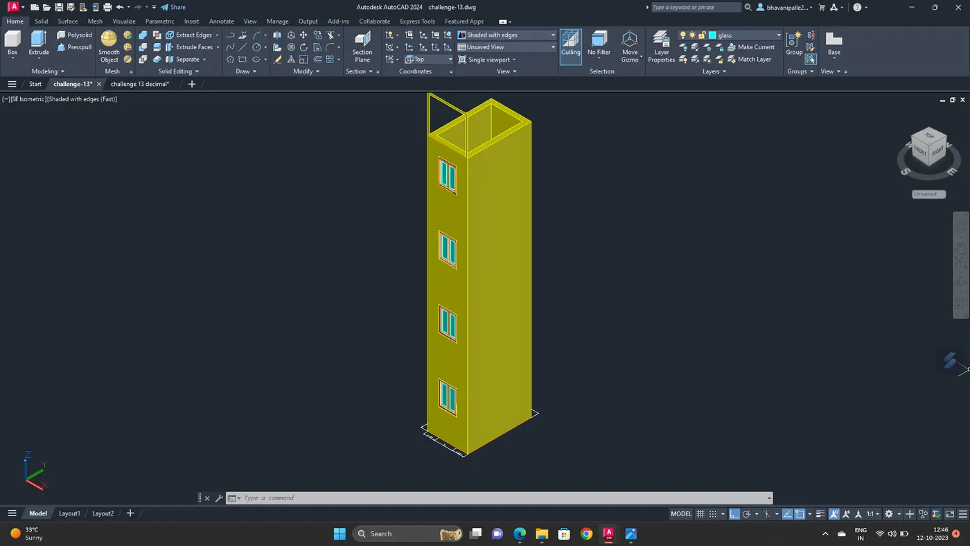
Copy them to create elevation view
Go to visualize command create new views
3.
AIM :
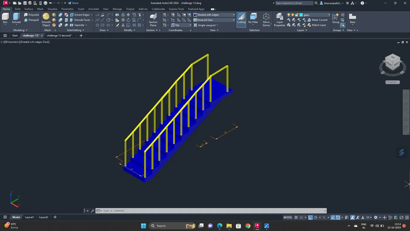
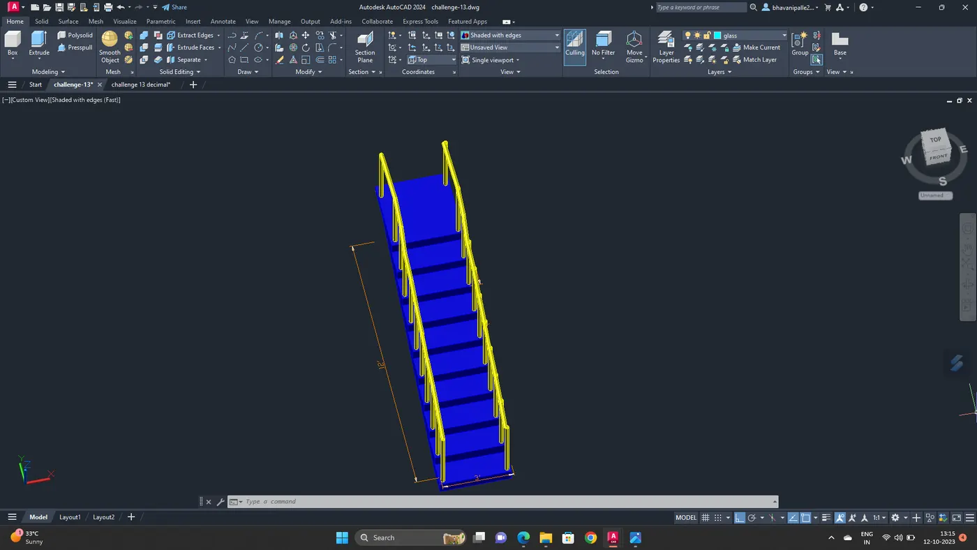
CREATE THE ISOMETRIC VIEW OF A STAIR WITH RAILING .ASSUME THE SIZE OF BALUSTARDES AND HAND RAILS
PROCEDURE :
Draw a rectangle of dimesion 3'x12'
Explode the rectangle
Offset the sides with distance 1''
Offset bottom edge to top with distance 1' 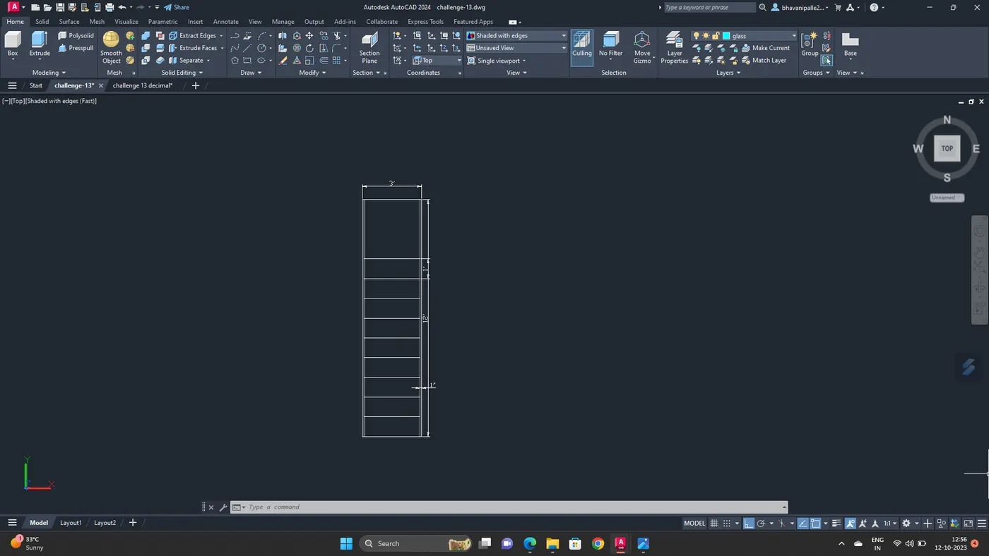
Change the view to 3d view
Create a region from side view of stairs
Extrude to a distance of 3'
Draw circle of dia 1''
Offset the circle with 2''
Change the circle into region
Extrude the region upto 3'
Copy hand rail on al, stairs
Copy the same in other side of the stairs
Draw a polyline connecting all top edges of hand rails
Draw a circle create region
By SWEEP command
select the circle as object and polyline as path
Create sweep
Copy the same as on ther side
Go to visualize create views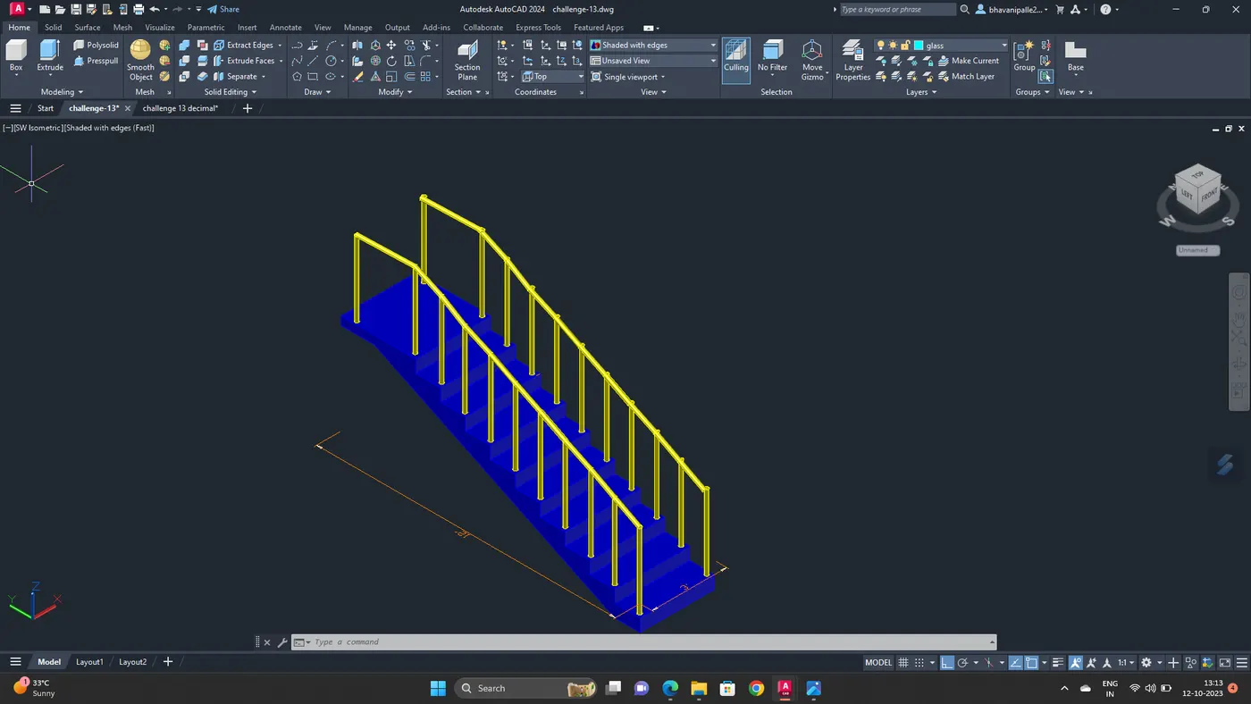
4.
AIM :
To draw 3D view of a wall with spread footing
PROCEDURE :
OPEN AUTO CAD
Set units in mm
Create layers
Draw a rectangle of dimesions 670x7500
Offset the rectangle to a distance of 120mm
Extrude all rectangles
Explode all rectangles delete top and bottom edges
Extend all rectangles to top
Select all colours and change their layers respectively
Give dimesion
Creating door block
Draw a rectangle
Draw another rectangle
Draw a line in between the rectangles
Draw an arc as door swing
Convert into block
Create door opening of 900mm at the middile
Add door block by rotating the door
Create door shade by dotted line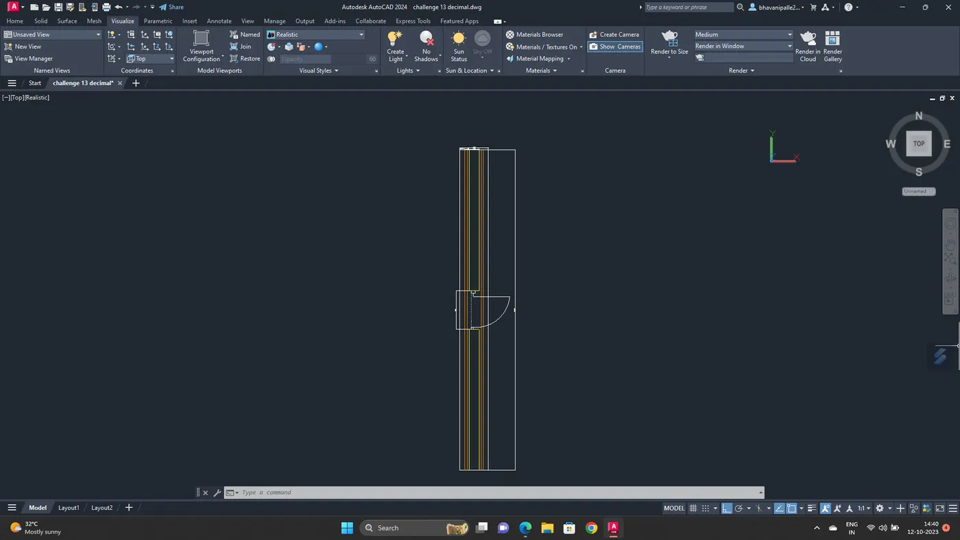
Creating Footing
Draw a rectangle of 670x300
Draw a rectangle of 430x400
Draw a rectangle of 330x400
Draw a rectangle of 230x600
Draw a rectangle of 2100X230
Draw a rectangle of 430x400
Draw a rectangle of 150X100
Create shade of door
Draw a rectangle of 230X1050
Create parapet wall
Create boundaries and extrude
RENDERING
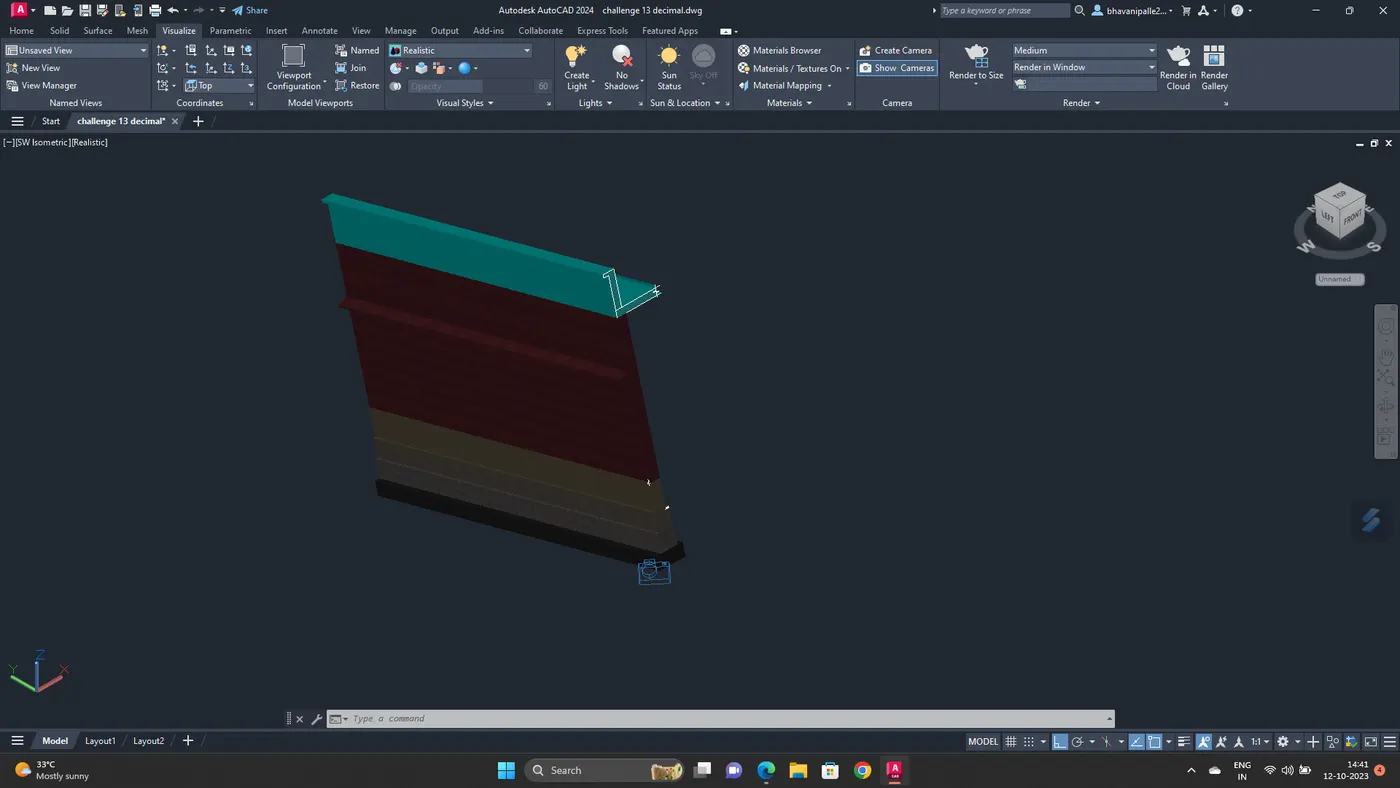
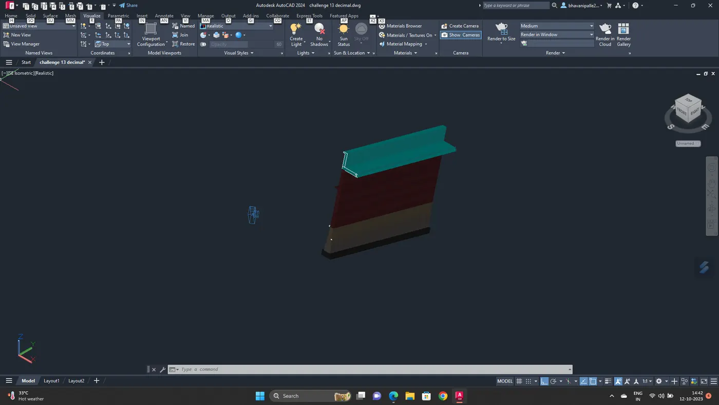
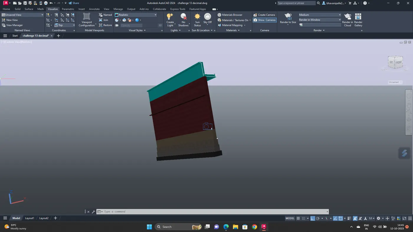
Go to material browser
The materials added for the components like concrete ,masonry etc
Box mapping is done for super structure
Camera placing
Create a circle
Region the circle and extrude upto some height
Go to visualize click on create camera
Place the camera on the circle
Adjust the view.
Create the views.