Creating 3D Isometric view of various structural elements in AutoCAD
- Aim is to create the 3D Isometric View of the building with plan and elevation given using 3D Modeling Workspace . I am going to use the drawings from the plan and elevation to quickly create boundary or regions and extrude the floorin,walls,windows and slab. I am going to use UCS Icon, View Cube and Navigation Bar to work easily in different sides of the drawing.
- First step is to open a new page and set the Drawing Units as shown.
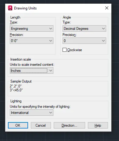
- I set the maximum limit of the screen
Command:Limmax 35’,35’
Command:Zoom>All
Workspace switching to 3D Modeling
- Command>Plan>current ucs
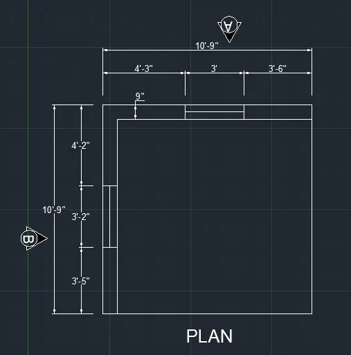
Using commands Rectangle, Offset,Line,Dimstyle, Dimlinear, Circle,polygon with 3 sides, text
I draw the Plan as shown.
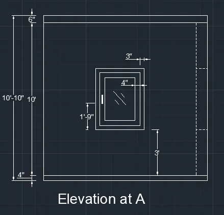
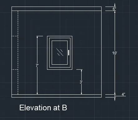
- Using the same commands I draw in XY plan the Elevation at A and Elevation at B.
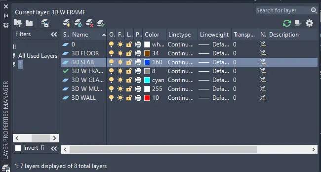
- I create 3d layers corresponding to floor, walls, window frame, window mullion, window glass,slab…
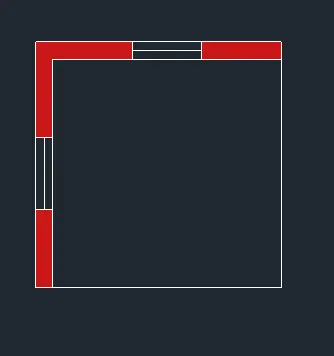
- At the Plan I Boundary the walls using layer 3D Wall
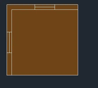
- Again at the plan using Layer 3D FLOOR I create a rectangle which includes the whole plan and Boundary>Region it in order to create the thicknes of the floor in the next step.
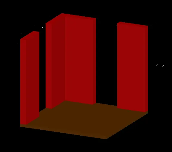
- I EXTRUDE the walls with high 10’ and the flooring with high 4”.
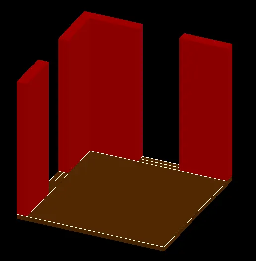
- I put 0 LAYER off : LAYOFF and that is the view named 1.
- V>VIEW>NEW to create a new view named 1 .
- I copy the elevation at A and rotate it with
Rotation axis:Y
Rotation angle -90 degree
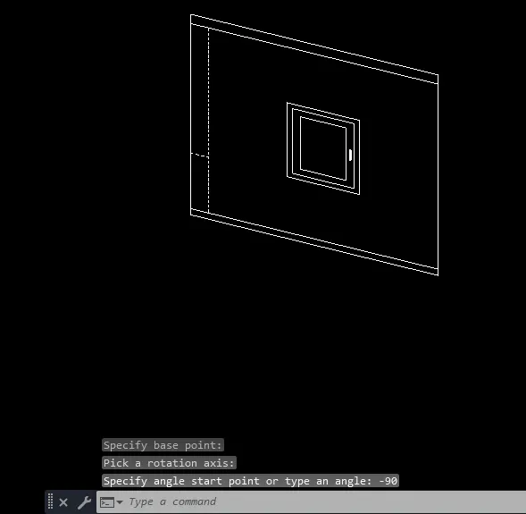
- I use commands: Region, surface trim to trim the extra surfaces and extrude 3” the window frame and the window mullion 1.2”,
In order to create the region for the window mullion I freez and turn off the layer window frame. The same I do to window mullion LAYOFF and freez, in order to create the window glass. Next I use command
3d Move 0,6” for the window mullion and 0.8” for the window glass.
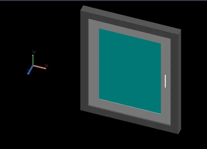
- This is a view of the corner of the window after the use of 3dMove
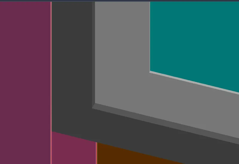
- I use again 3DMove to move the window from where I created it, to the building.
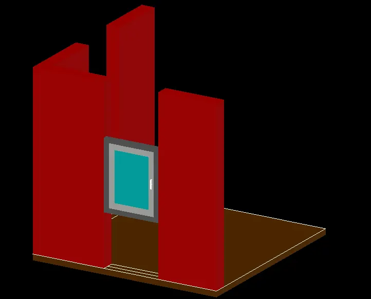
- Using command rectangular and placing the UCS as shown I create 2 rectangles in two extremitetes of the wall above and below the window, and then Extrude them 3’ each as shown.
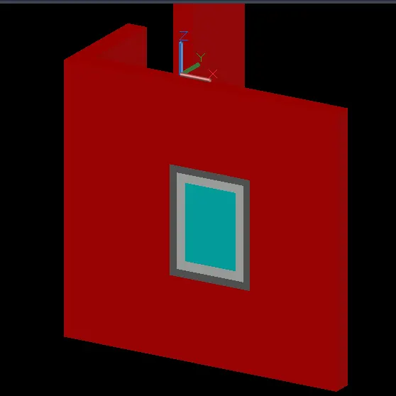
- I group the window and then 3DMove it 2” inside the wall
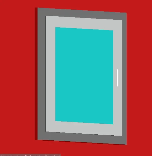
- I create a view 2
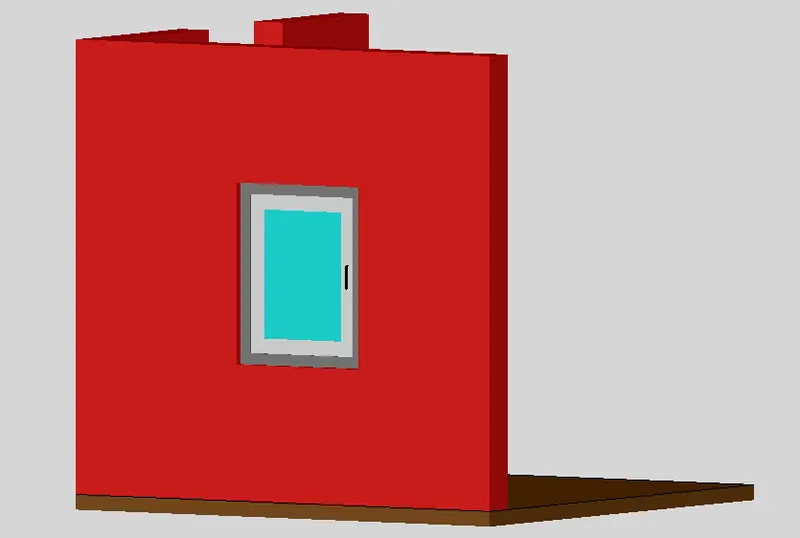
- This is a view of the building from inside.
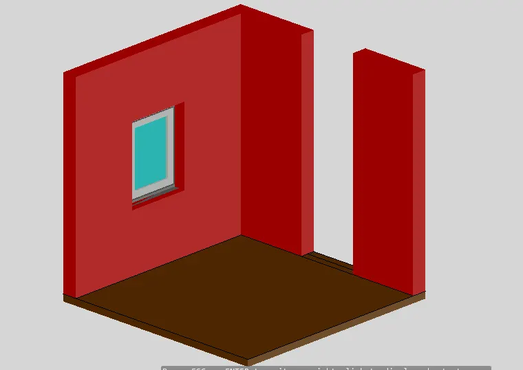
- I create View 3 and freez and Layoff 3D Floor layer.
Same as above I create rectangles on both sides of the wall where the window is going to be placed, I extrude 3’ each side, and unfreez and Layon 3dfloor layer.
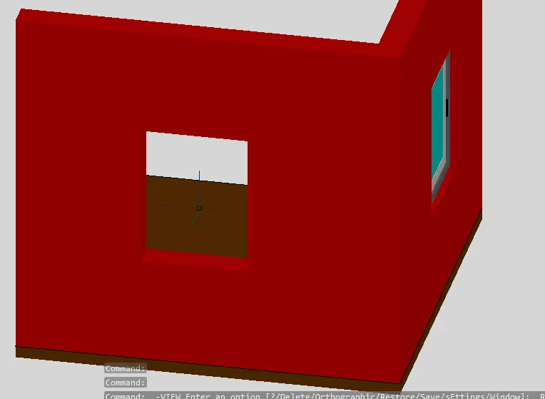
- I copy the elevation at B 3DRotate it
Axis of rotation: X, ROTATION ANGLE 90 degree.
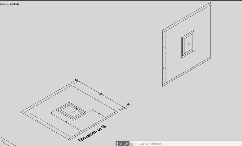
- Same as the other window I create the window of the elevation at B.
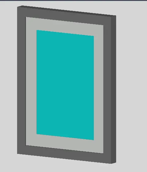
- Then using 3DMove I move it at the place required.
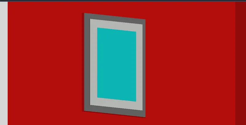
- This is a view of the drawing at this point.
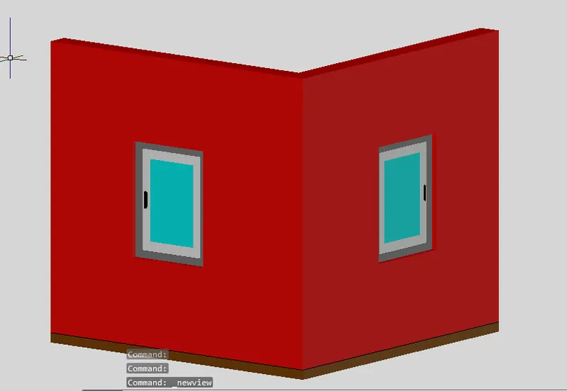
- In the field I draw a rectangle with dimensions of the Plan 10’9”x10’9” and I put layer 3DSlab current. Then I Extrude it 6”.
- Using command: 3DMove, I place the rectangle on top of the wall as the slab with 6” thicknes.
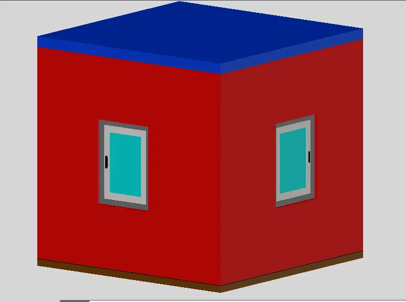
- This is a view of the building finished from outside.
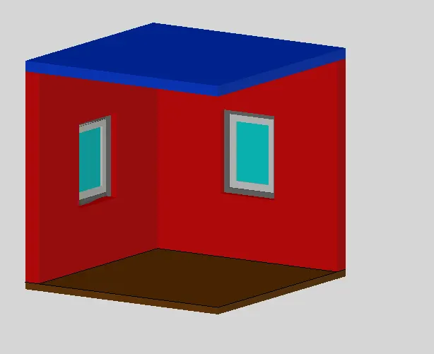
- This is a view of the building finished from inside.
- Aim is to create the 3D Isometric View of the building façade with plan and elevation given using 3D Modeling Workspace . I am going to use the drawings from the plan and elevation to quickly create boundary or regions and extrude the walls and windows . I am going to use UCS Icon, View Cube and Navigation Bar to work easily in different sides of the drawing.
- Command>Plan>current ucs
Using commands Rectangle, Offset,Line,Dimstyle, Dimlinear, text….
I draw the PLAN, WINDOW AND ELEVATION as shown.
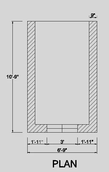
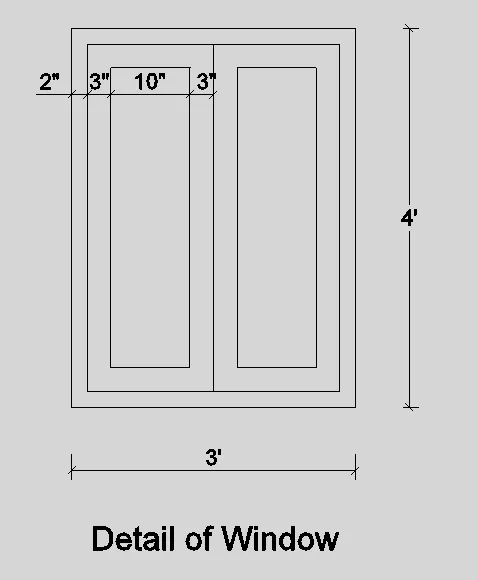
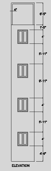
- I CREATE 3DLayers for the window frame, window mullion and window glass, and a layer for the 3DWall.
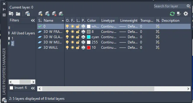
- Next I copy the plan of the building and Boundary the walls using layer 3DWall.
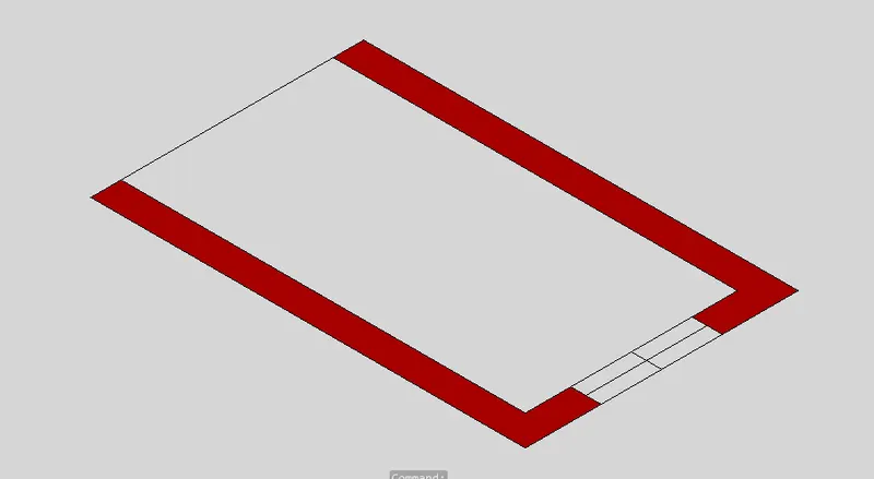
- I extrude the walls with WALL HIGH 9’11”.
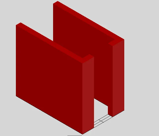
- Placing UCS as shoun and using command Rectangle I create 2 rectanglesin the bottom and above the space where the window is going to be placed, and I extrude the bottom rec with WALL high 4’6” AND the above wall high is 1’5”.
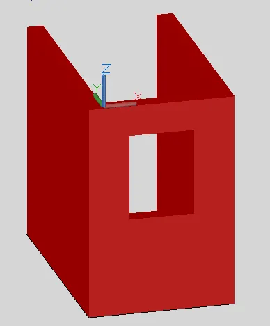
- I copy the window drawing on the plan and I use command 3DRotate to rotate it.
Axis of rotation is X with a 90 degree rotation.
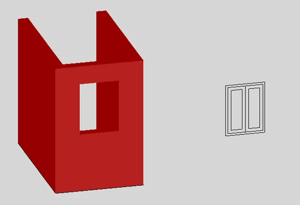
- I use commands: Region, surface trim to trim the extra surfaces and extrude 3” the window frame.
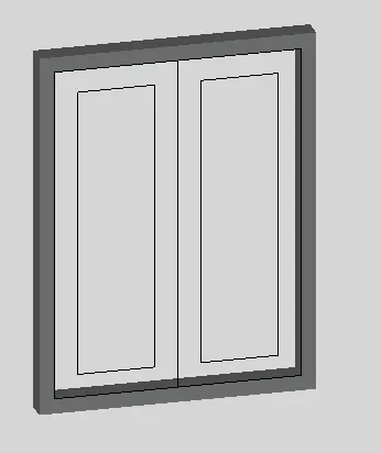
- In order to create the region for the window mullion I freez and turn off the layer window frame.
Then I use commands: Region, surface trim to trim the extra surfaces and extrude the window mullion 1.2”,
The same I do to window mullion LAYOFF and freez, in order to create the window glass. Next I use command
3d Move 0,6” for the window mullion and 0.8” for the window glass.
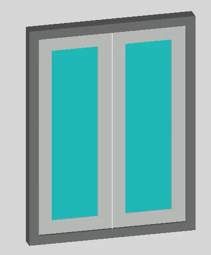
- Using command 3DMove, I move the window as required.
- Then I group the window and use again the command 3DMove to move the window inside the wall with 2”.
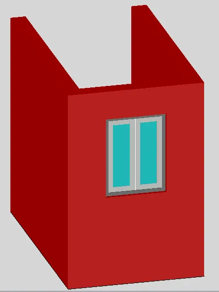
- I use command 3DCopy to copy the entire floor and create 3 more floors on top of each other.
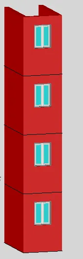
- I turn off all the layers, I keep only 0 layer on. Now I delete the extra lines in between floors.
- Then I use command Union to union the building floors.
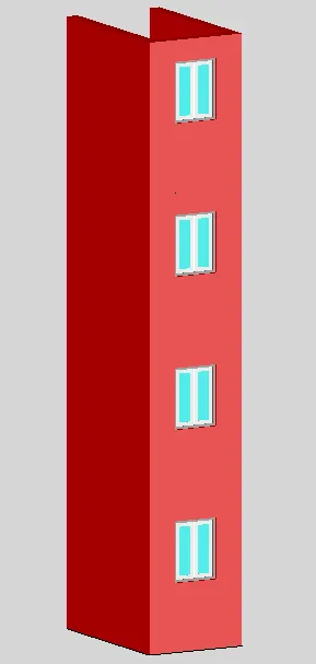
- PLAN>Current UCS
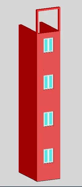
- Using layer 3D wall I create the wall on top of the building with high 6’5” and 4” wall width.
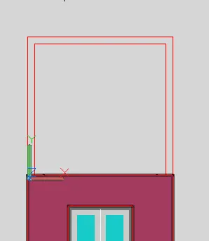
- I Boundary the walls created and Extrude with 9” thickness.

- This is the final look of the building façade with 4 floors and a window in each floor.
- Aim is to create the 3D Isometric View of the stairs with railing, with plan and elevation given using 3D Modeling Workspace . I am going to use the drawings from the plan and elevation to quickly create boundary or regions and extrude the steps and the railing . I am going to use UCS Icon, View Cube and Navigation Bar to work easily in different sides of the drawing.
- Command>Plan>current ucs
Using commands Rectangle, Offset,Line,Dimstyle, Dimlinear, text….
I draw the PLAN AND ELEVATION of the stairs as shown.
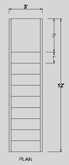
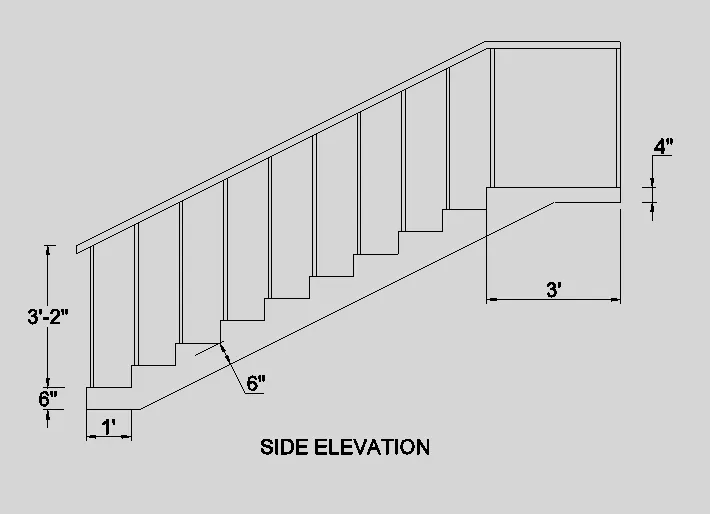
- I create layers for the 3DSlab of the stairs and 3DHandrail.
- I copy the plan of the stairs and Region it using 3DSlab layer.
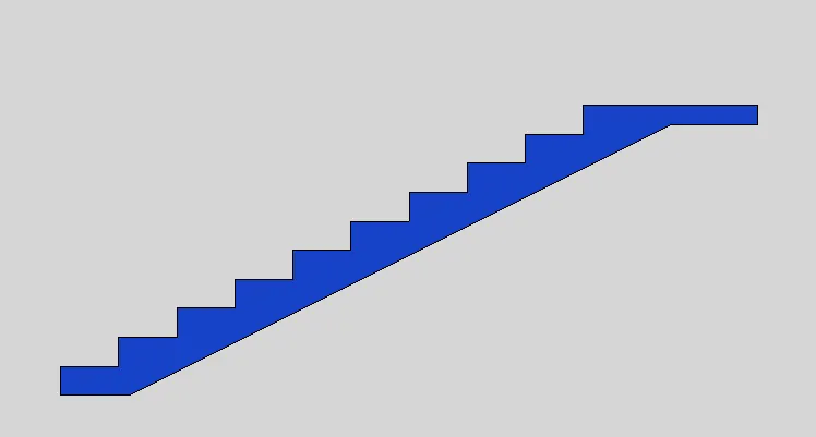
- Using command 3DRotate I rotate the stair plan with:
ROTATION AXIS X, 90 DEGREE.
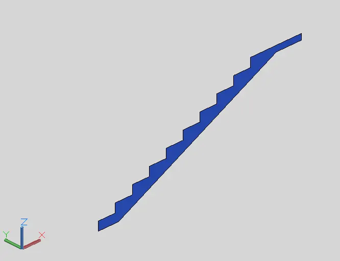
- I extrude the slab of the stairs with 3’.
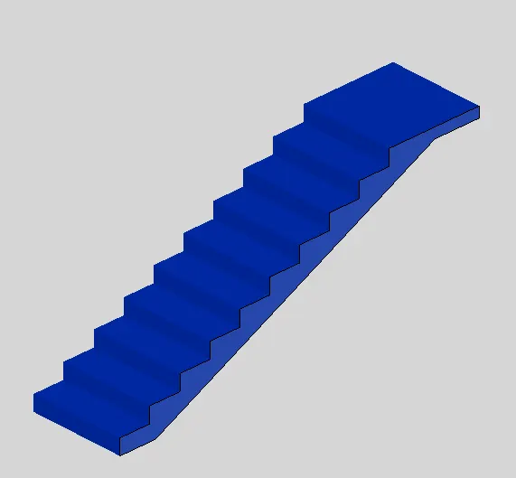
- I place the UCS at the step, draw a circle of 1” diameter and extrude it with high 3’1” using layer 3DHandrail.
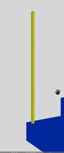
- I use command 3DMirror to mirror it in the other side of the stair and then I use command 3DCopy to copy it in each step.
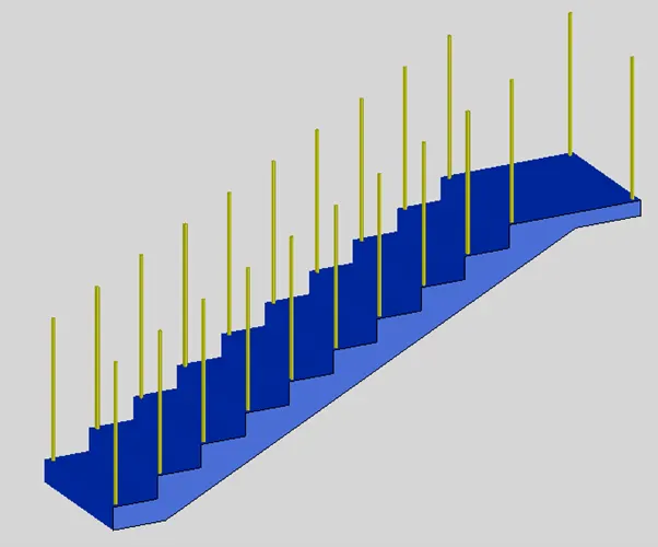
- I place UCS as shown, and draw polyline in each side of the handrail.
I draw two circles in the field as well with diameter 1” using layer 3DStair Handrail 1.
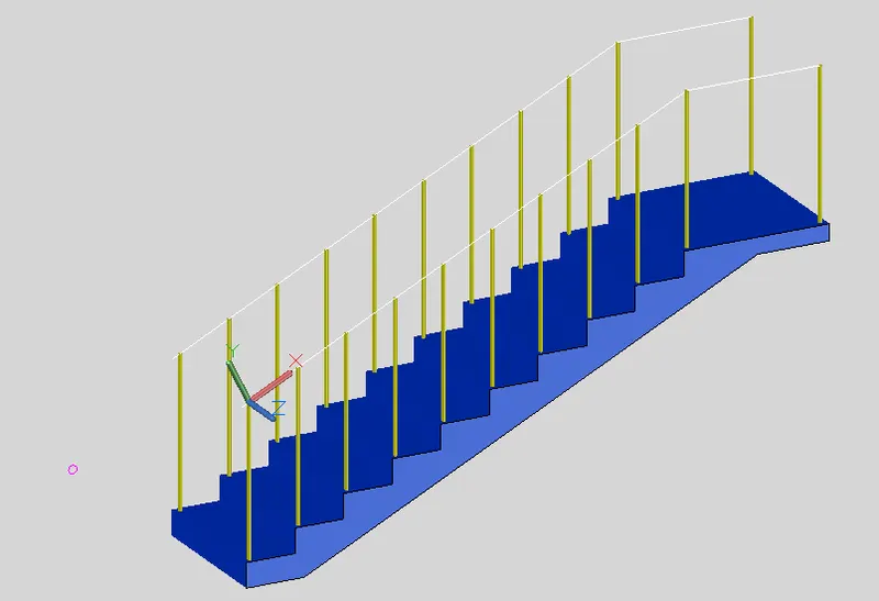
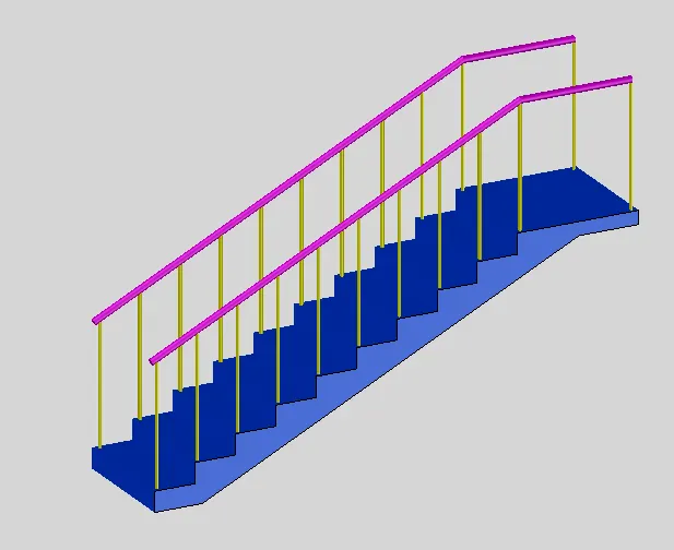
- I use command Sweep to sweep the circles into the path of the polylines.
- And this is the 3D Model of the stairs with railing.
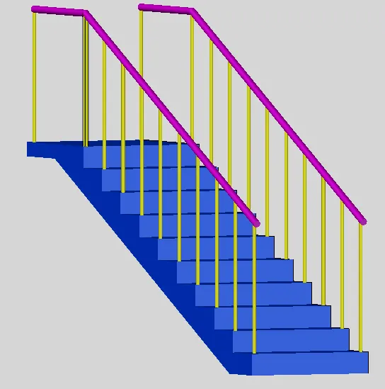
- Aim is to create the 3D Isometric View of the wall with spread footing, with plan and section of wall footing given using 3D Modeling Workspace .
Next I have to create a rendered view of the wall with spread footing with matirials of my choice.
I am going to use the drawings from the plan and elevation to quickly create boundary or regions and extrude the steps and the railing . I am going to use UCS Icon, View Cube and Navigation Bar to work easily in different sides of the drawing.
- I open a new page and set the drawing units in milimeters .
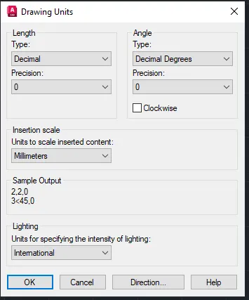
- I set the maximum limit of the screen:
Command : Limmax > 15000,15000 mm
Zoom>all
- Command>Plan>current ucs
Using commands Rectangle, Offset,Line,Dimstyle, Dimlinear, text Hatch….
I draw the PLAN and SECTION OF WALL FOOTING as shown.
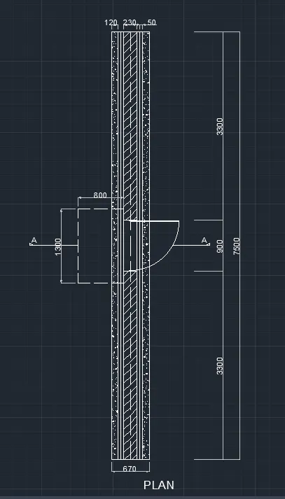
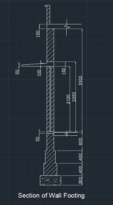
- I create Layers for the 3D Wall with spread footing.
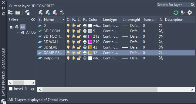
- I copy the plan of the wall footing and create Boundary out of each different component of the wall footing including walls, slabs, floor, footing , concrete footing and damp proof course.
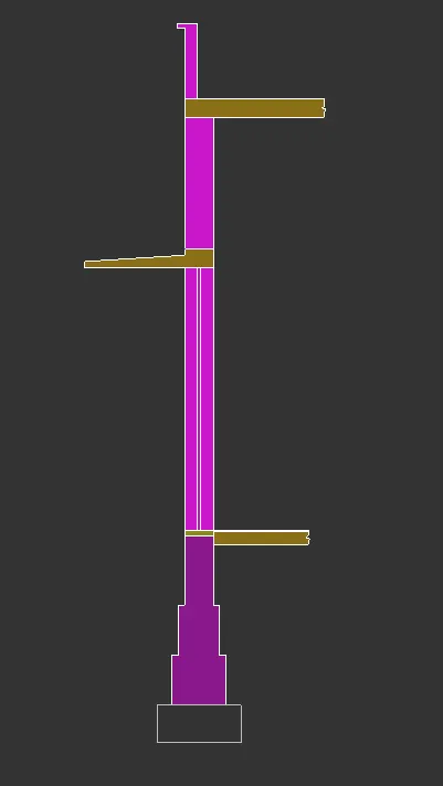
- I use command 3DRotate to rotate the plan of the wall footing:
ROTATION AXIS X, 90 DEGREE.
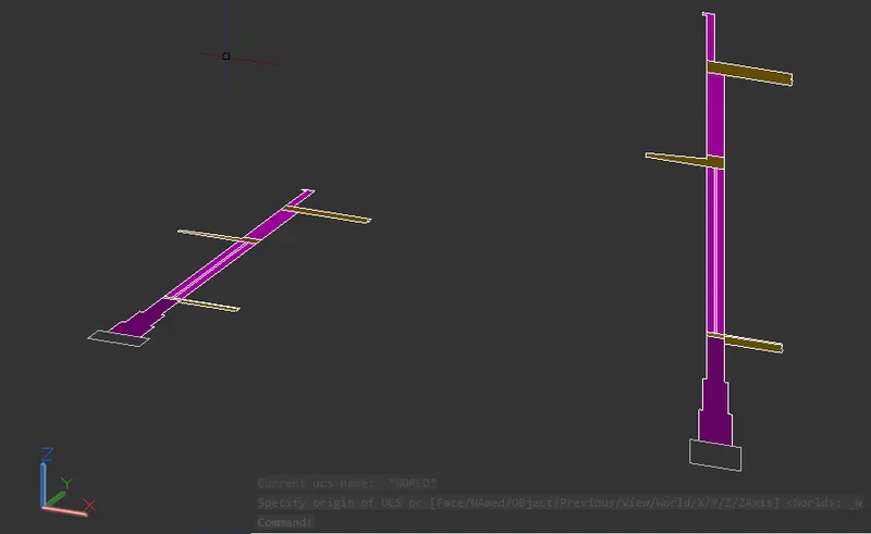
- Now I copy the plan of the wall, and place the section of the wall footing at the section in a 3d view.
- Then I extrude each element of the section in one side, and use command Presspull in the other side to create the walls, flooring, slabs, footing, damp waterproof course… where possible.
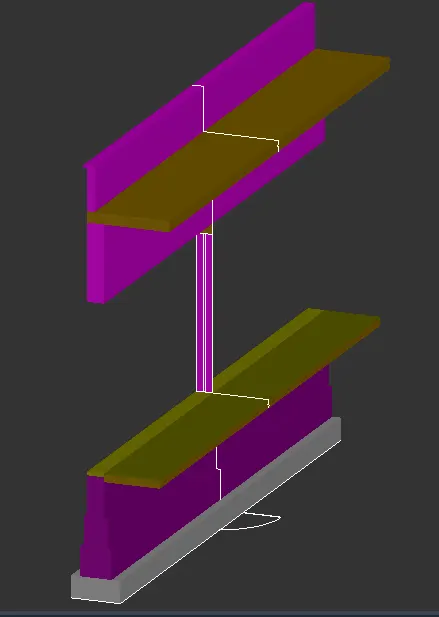
- Then I place the UCS as shown, and create 2 rectangles with layer 3dwall on.
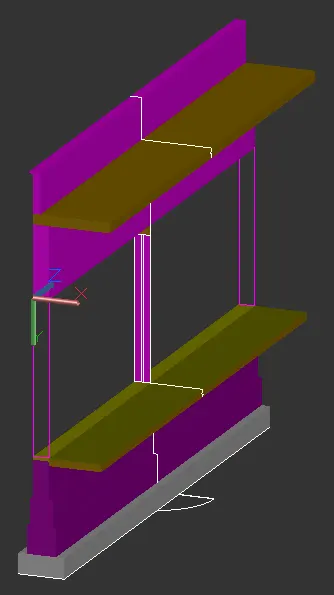
- I EXTRUDE each rectangle 3300mm on both sides as shown and the 3d wall with spread footing with the door opening is created.
- Is left only the slab on top of the door.
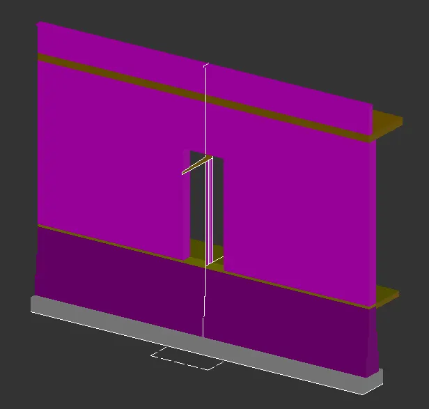
- I Exrude the slab on top of the door up to the corner of the drawing in plan, and in the other side I use command Presspull.
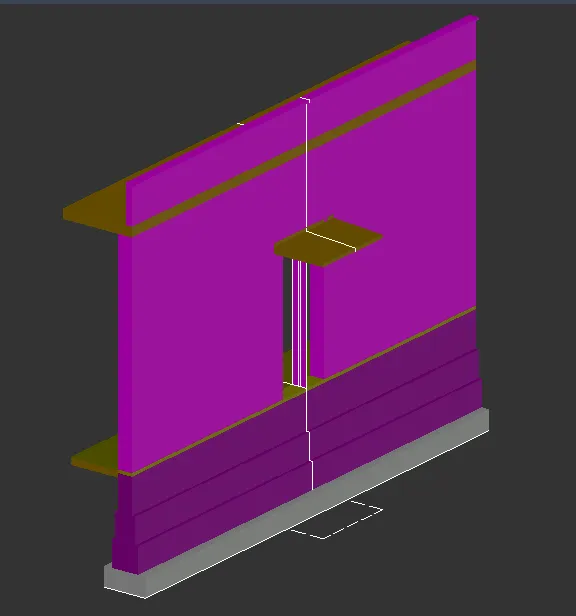
- I Turn Off and Freez all layers, I only keep on layer 0, and delete the extra lines of the section of the wall footing.
- This is the view of the 3D Wall with e Spread Footing.
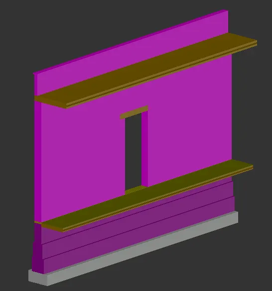
- Now I go to Visualize>Material Browser and choose the materials I am going to assign to the 3d object.
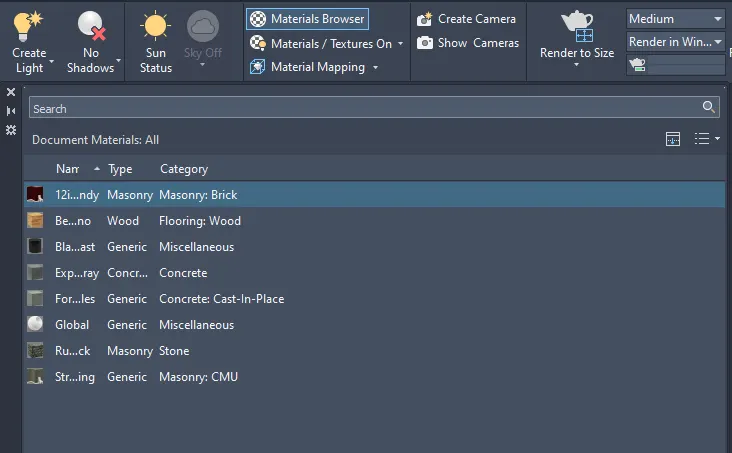
- While in the Material Browser table, I select the elements of the 3d object one by one and assign the materials as shown.
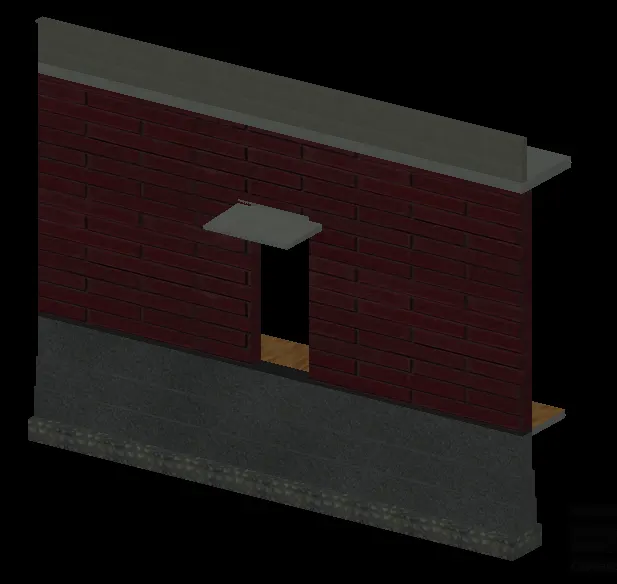
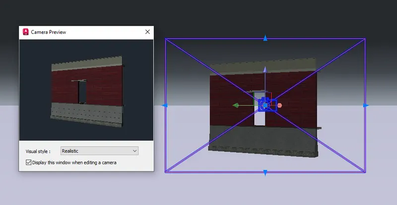
- To create a camera view I create a cylinder where I am going to place the camera, go to Visualize>Create Camera and name it Camera1.
Double click at the camera to see the camera preview.
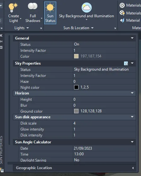
- Now I put on Sun Status, Full Shadow on, Sky and Background and illumination on with the time of the day 13:00.
- Visualize> Render
- To realize the Rendering the field have to be in a PRESPECTIVE mode.
I adjust the rendering details as shown.
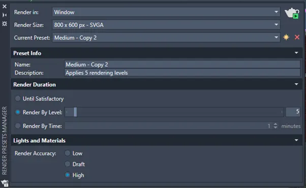
- Command RR to Render the 3D Wall with Spread Footing in different positions as saved in views render 1 and render 2.
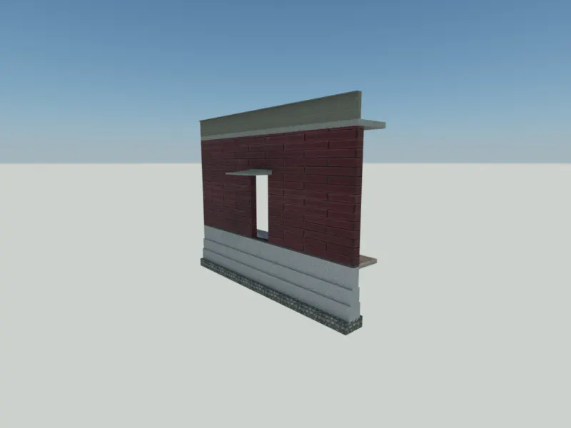
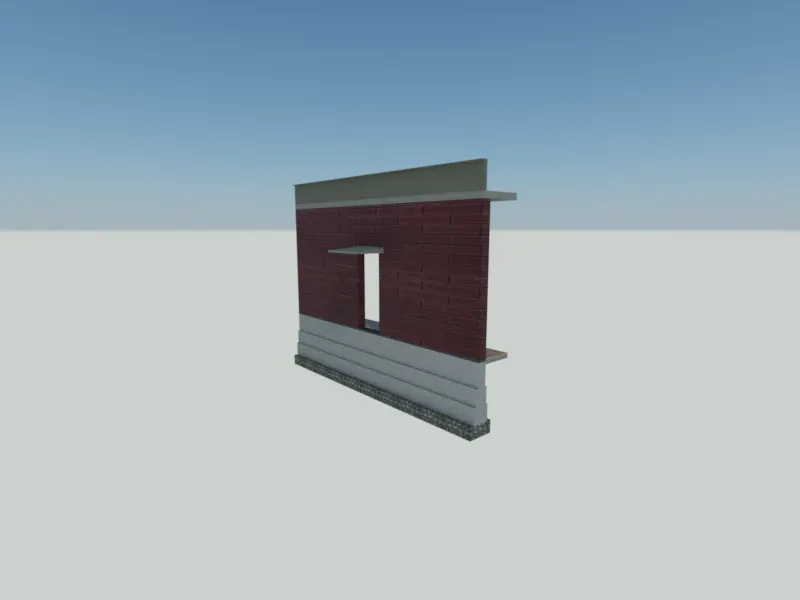
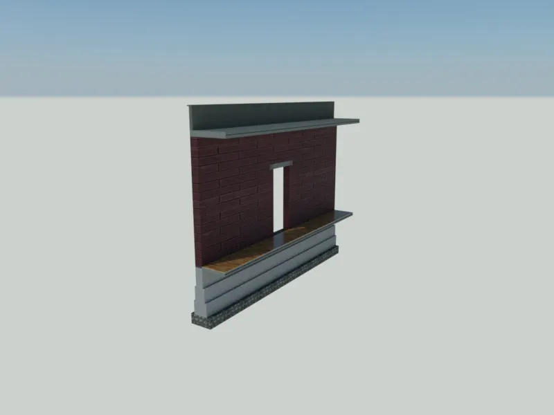
- Visualization>Render>Render Environment and Exposure
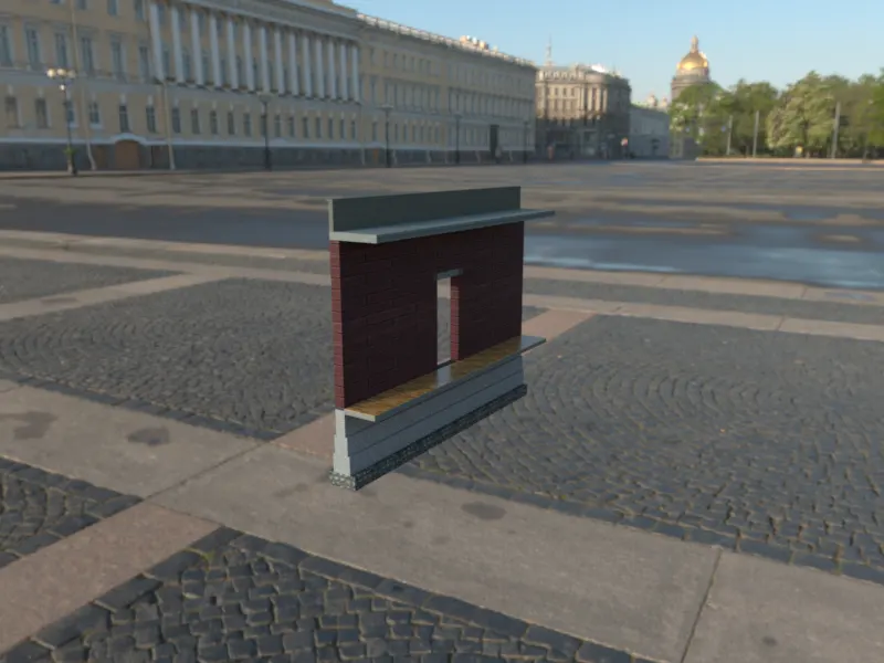
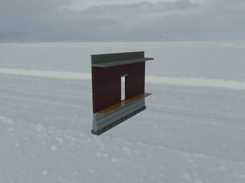
- I choose Plaza and Snow Field as a background image.
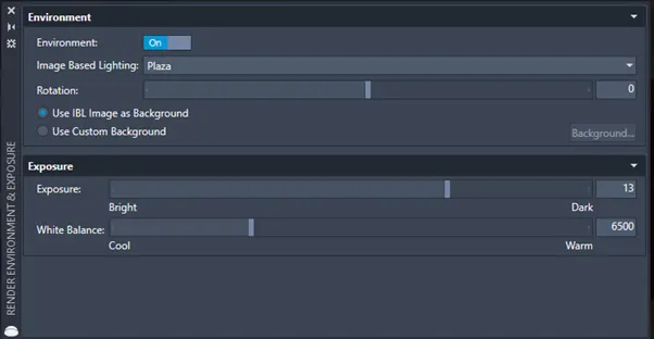
- Command RR to Render the 3D Wall with Spread Footing with a Village Background and a Snow Background.
- Note: Thank you very much for the grades and notes. I am gratefull.