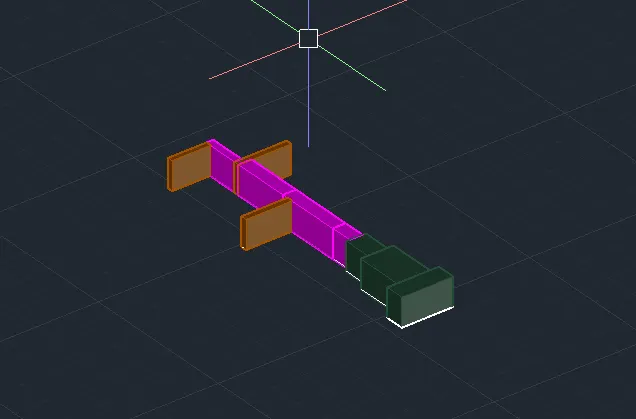
Creating 3D Isometric view of various structural elements in AutoCAD
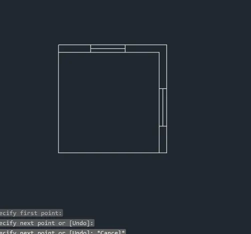
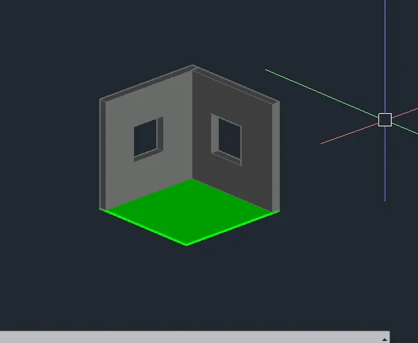
1. Aim: Create a 3D Isometric View of the building with plan and elevation given.
procedure: The following steps should be followed as a procedure to draw a given 3D Isometric View of the building with plan and elevation using autocad
- To draw the given 3D Isometric View of the building with plan and elevation in autocad, the following steps should be followed as a procedure. At first open the AutoCAD and set dimensions that the dimensions are in feets and inches.
- Then enter the Line command in AutoCAD and after that enter the first point of the given diagram as that line should be started at the point in the coordinate system.
- Then with that point draw a rectangle using rectangle command using the dimensions of the rectangle as length is 2'6" and width is 2'6".
- by using the offset command in autocad make offsset of 2' for the side of a table ie enter the dimension of the offset as 2'.
- then select the last line of the rectangle and make offset of 2.5' ie the width of the both side of a table by using the offset command in autocad.
- Open AutoCad Selecting Imperial system Command UN(units) and selecting Engineering with precision of 0’-0.0”. Command LIMITS and having limit of (0’,0’) in lower left corner and (100’,100’) in upper right corner. Command ZOOM and selecting All. Changing the Workspace from Drafting and annotation to the 3D modelling.
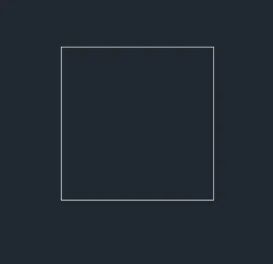
- To draw the 3d model table in autocad, the following steps should be followed as a procedure. At first open the AutoCAD and set dimensions that the dimensions are in feets and inches.
- Then enter the Line command in AutoCAD and after that enter the first point of the given diagram as that line should be started at the point in the coordinate system.
- Then with that point draw a rectangle using rectangle command using the dimensions of the rectangle as length is 2'6" and width is 2'6".
- by using the offset command in autocad make offsset of 2' for the side of a table ie enter the dimension of the offset as 2'.
- then select the last line of the rectangle and make offset of 2.5' ie the width of the both side of a table by using the offset command in autocad.
- Open AutoCad Selecting Imperial system Command UN(units) and selecting Engineering with precision of 0’-0.0”. Command LIMITS and having limit of (0’,0’) in lower left corner and (100’,100’) in upper right corner. Command ZOOM and selecting All. Changing the Workspace from Drafting and annotation to the 3D modelling.
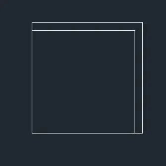
- Then enter the Line command in AutoCAD and after that enter the first point of the given diagram as that line should be started at the point in the coordinate system.
- Then with that point draw a rectangle using rectangle command using the dimensions of the rectangle as length is 2'6" and width is 2'6".
- by using the offset command in autocad make offsset of 2' for the side of a table ie enter the dimension of the offset as 2'.
- then select the last line of the rectangle and make offset of 2.5' ie the width of the both side of a table by using the offset command in autocad.
- Open AutoCad Selecting Imperial system Command UN(units) and selecting Engineering with precision of 0’-0.0”. Command LIMITS and having limit of (0’,0’) in lower left corner and (100’,100’) in upper right corner. Command ZOOM and selecting All. Changing the Workspace from Drafting and annotation to the 3D modelling.
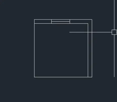
- Then enter the Line command in AutoCAD and after that enter the first point of the given diagram as that line should be started at the point in the coordinate system.
- Then with that point draw a rectangle using rectangle command using the dimensions of the rectangle as length is 2'6" and width is 2'6".
- by using the offset command in autocad make offsset of 2' for the side of a table ie enter the dimension of the offset as 2'.
- then select the last line of the rectangle and make offset of 2.5' ie the width of the both side of a table by using the offset command in autocad.
- Open AutoCad Selecting Imperial system Command UN(units) and selecting Engineering with precision of 0’-0.0”. Command LIMITS and having limit of (0’,0’) in lower left corner and (100’,100’) in upper right corner. Command ZOOM and selecting All. Changing the Workspace from Drafting and annotation to the 3D modelling.
- To draw the 3d model table in autocad, the following steps should be followed as a procedure. At first open the AutoCAD and set dimensions that the dimensions are in feets and inches.
- Then enter the Line command in AutoCAD and after that enter the first point of the given diagram as that line should be started at the point in the coordinate system.
- Then with that point draw a rectangle using rectangle command using the dimensions of the rectangle as length is 2'6" and width is 2'6".
- by using the offset command in autocad make offsset of 2' for the side of a table ie enter the dimension of the offset as 2'.
- then select the last line of the rectangle and make offset of 2.5' ie the width of the both side of a table by using the offset command in autocad.
- Open AutoCad Selecting Imperial system Command UN(units) and selecting Engineering with precision of 0’-0.0”. Command LIMITS and having limit of (0’,0’) in lower left corner and (100’,100’) in upper right corner. Command ZOOM and selecting All. Changing the Workspace from Drafting and annotation to the 3D modelling
- Wireframe modeling is useful for initial design iterations and as reference geometry, serving as a 3D framework for subsequent modeling or modification.
- Solid modeling is efficient to use, easy to combine primitives and extruded profiles, and offers mass properties and sectioning capabilities.
- Surface modeling offers fine control over curved surfaces for precise manipulation and analysis.
- Mesh modeling provides freeform sculpting, creasing, and smoothing capabilities.
- A 3D model can include combinations of these technologies, and you can convert between them. For example, you can convert a primitive 3D solid pyramid to a 3D mesh to perform mesh smoothing. You can then convert the mesh to a 3D surface or back to a 3D solid to take advantage of their respective modeling features.
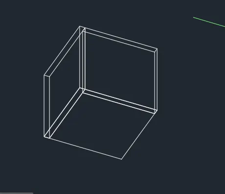
- The command repeats automatically until you press Esc, Enter, or the spacebar. The following prompts are displayed. Object or bounded area Select the object, bounded area, or 3D solid face that you want to modify. Selecting a face extrudes the face without affecting the adjacent faces. If you Ctrl+click a face, the face is offset, and the change also affects the adjacent faces.
- Open AutoCad Selecting Imperial system Command UN(units) and selecting Engineering with precision of 0’-0.0”. Command LIMITS and having limit of (0’,0’) in lower left corner and (100’,100’) in upper right corner. Command ZOOM and selecting All. Changing the Workspace from Drafting and annotation to the 3D modelling
- Wireframe modeling is useful for initial design iterations and as reference geometry, serving as a 3D framework for subsequent modeling or modification.
- Solid modeling is efficient to use, easy to combine primitives and extruded profiles, and offers mass properties and sectioning capabilities.
- Surface modeling offers fine control over curved surfaces for precise manipulation and analysis.
- Mesh modeling provides freeform sculpting, creasing, and smoothing capabilities.
- A 3D model can include combinations of these technologies, and you can convert between them. For example, you can convert a primitive 3D solid pyramid to a 3D mesh to perform mesh smoothing. You can then convert the mesh to a 3D surface or back to a 3D solid to take advantage of their respective modeling features.
- Wireframe modeling is useful for initial design iterations and as reference geometry, serving as a 3D framework for subsequent modeling or modification.
- Solid modeling is efficient to use, easy to combine primitives and extruded profiles, and offers mass properties and sectioning capabilities.
- Surface modeling offers fine control over curved surfaces for precise manipulation and analysis.
- Mesh modeling provides freeform sculpting, creasing, and smoothing capabilities.
- A 3D model can include combinations of these technologies, and you can convert between them. For example, you can convert a primitive 3D solid pyramid to a 3D mesh to perform mesh smoothing. You can then convert the mesh to a 3D surface or back to a 3D solid to take advantage of their respective modeling features.
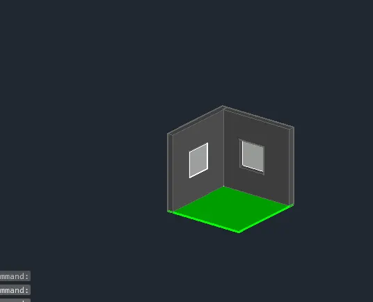
2. Aim: To Create the 3D View of the Building Façade as given in the plan and elevation. Also, see the detail of the window.
procedure: The following steps should be followed as a procedure to draw a given 3D Isometric View of the building with plan and elevation using autocad
- To draw the given 3D Isometric View of the building with plan and elevation in autocad, the following steps should be followed as a procedure. At first open the AutoCAD and set dimensions that the dimensions are in feets and inches.
- Then enter the Line command in AutoCAD and after that enter the first point of the given diagram as that line should be started at the point in the coordinate system.
- Then with that point draw a rectangle using rectangle command using the dimensions of the rectangle as length is 2'6" and width is 2'6".
- by using the offset command in autocad make offsset of 2' for the side of a table ie enter the dimension of the offset as 2'.
- then select the last line of the rectangle and make offset of 2.5' ie the width of the both side of a table by using the offset command in autocad.
- Open AutoCad Selecting Imperial system Command UN(units) and selecting Engineering with precision of 0’-0.0”. Command LIMITS and having limit of (0’,0’) in lower left corner and (100’,100’) in upper right corner. Command ZOOM and selecting All. Changing the Workspace from Drafting and annotation to the 3D modelling.
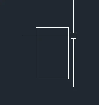
- To draw the 3d model table in autocad, the following steps should be followed as a procedure. At first open the AutoCAD and set dimensions that the dimensions are in feets and inches.
- Then enter the Line command in AutoCAD and after that enter the first point of the given diagram as that line should be started at the point in the coordinate system.
- Then with that point draw a rectangle using rectangle command using the dimensions of the rectangle as length is 2'6" and width is 2'6".
- by using the offset command in autocad make offsset of 2' for the side of a table ie enter the dimension of the offset as 2'.
- then select the last line of the rectangle and make offset of 2.5' ie the width of the both side of a table by using the offset command in autocad.
- Open AutoCad Selecting Imperial system Command UN(units) and selecting Engineering with precision of 0’-0.0”. Command LIMITS and having limit of (0’,0’) in lower left corner and (100’,100’) in upper right corner. Command ZOOM and selecting All. Changing the Workspace from Drafting and annotation to the 3D modelling.
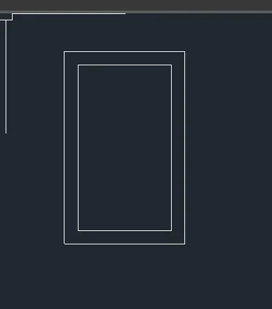
- To draw the 3d model table in autocad, the following steps should be followed as a procedure. At first open the AutoCAD and set dimensions that the dimensions are in feets and inches.
- Then enter the Line command in AutoCAD and after that enter the first point of the given diagram as that line should be started at the point in the coordinate system.
- Then with that point draw a rectangle using rectangle command using the dimensions of the rectangle as length is 2'6" and width is 2'6".
- by using the offset command in autocad make offsset of 2' for the side of a table ie enter the dimension of the offset as 2'.
- then select the last line of the rectangle and make offset of 2.5' ie the width of the both side of a table by using the offset command in autocad.
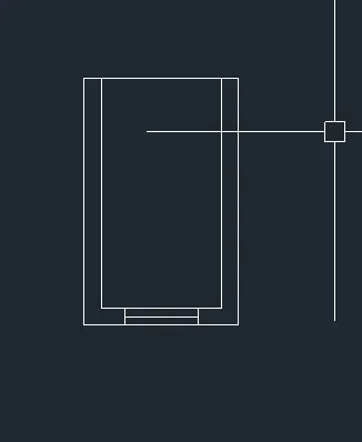
- Then enter the Line command in AutoCAD and after that enter the first point of the given diagram as that line should be started at the point in the coordinate system.
- Then with that point draw a rectangle using rectangle command using the dimensions of the rectangle as length is 2'6" and width is 2'6".
- by using the offset command in autocad make offsset of 2' for the side of a table ie enter the dimension of the offset as 2'.
- then select the last line of the rectangle and make offset of 2.5' ie the width of the both side of a table by using the offset command in autocad.
- Open AutoCad Selecting Imperial system Command UN(units) and selecting Engineering with precision of 0’-0.0”. Command LIMITS and having limit of (0’,0’) in lower left corner and (100’,100’) in upper right corner. Command ZOOM and selecting All. Changing the Workspace from Drafting and annotation to the 3D modelling.
- Wireframe modeling is useful for initial design iterations and as reference geometry, serving as a 3D framework for subsequent modeling or modification.
- Solid modeling is efficient to use, easy to combine primitives and extruded profiles, and offers mass properties and sectioning capabilities.
- Surface modeling offers fine control over curved surfaces for precise manipulation and analysis.
- Mesh modeling provides freeform sculpting, creasing, and smoothing capabilities.
- A 3D model can include combinations of these technologies, and you can convert between them. For example, you can convert a primitive 3D solid pyramid to a 3D mesh to perform mesh smoothing. You can then convert the mesh to a 3D surface or back to a 3D solid to take advantage of their respective modeling features.
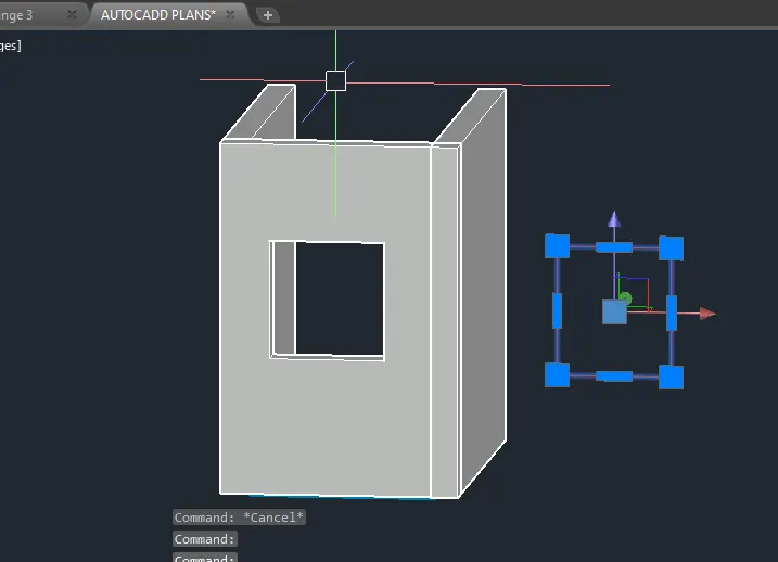
- Then with that point draw a rectangle using rectangle command using the dimensions of the rectangle as length is 2'6" and width is 2'6".
- by using the offset command in autocad make offsset of 2' for the side of a table ie enter the dimension of the offset as 2'.
- then select the last line of the rectangle and make offset of 2.5' ie the width of the both side of a table by using the offset command in autocad.
- Open AutoCad Selecting Imperial system Command UN(units) and selecting Engineering with precision of 0’-0.0”. Command LIMITS and having limit of (0’,0’) in lower left corner and (100’,100’) in upper right corner. Command ZOOM and selecting All. Changing the Workspace from Drafting and annotation to the 3D modelling.
- Wireframe modeling is useful for initial design iterations and as reference geometry, serving as a 3D framework for subsequent modeling or modification.
- Solid modeling is efficient to use, easy to combine primitives and extruded profiles, and offers mass properties and sectioning capabilities.
- Surface modeling offers fine control over curved surfaces for precise manipulation and analysis.
- Mesh modeling provides freeform sculpting, creasing, and smoothing capabilities.
- A 3D model can include combinations of these technologies, and you can convert between them. For example, you can convert a primitive 3D solid pyramid to a 3D mesh to perform mesh smoothing. You can then convert the mesh to a 3D surface or back to a 3D solid to take advantage of their respective modeling features.
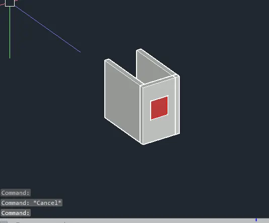
- To draw the given 3D Isometric View of the building with plan and elevation in autocad, the following steps should be followed as a procedure. At first open the AutoCAD and set dimensions that the dimensions are in feets and inches.
- Then enter the Line command in AutoCAD and after that enter the first point of the given diagram as that line should be started at the point in the coordinate system.
- Then with that point draw a rectangle using rectangle command using the dimensions of the rectangle as length is 2'6" and width is 2'6".
- by using the offset command in autocad make offsset of 2' for the side of a table ie enter the dimension of the offset as 2'.
- then select the last line of the rectangle and make offset of 2.5' ie the width of the both side of a table by using the offset command in autocad.
- Open AutoCad Selecting Imperial system Command UN(units) and selecting Engineering with precision of 0’-0.0”. Command LIMITS and having limit of (0’,0’) in lower left corner and (100’,100’) in upper right corner. Command ZOOM and selecting All. Changing the Workspace from Drafting and annotation to the 3D modelling
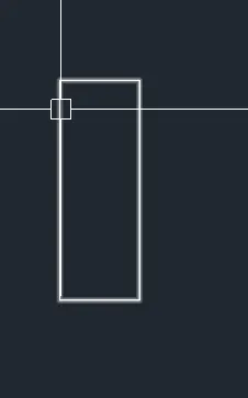
- Then with that point draw a rectangle using rectangle command using the dimensions of the rectangle as length is 2'6" and width is 2'6".
- by using the offset command in autocad make offsset of 2' for the side of a table ie enter the dimension of the offset as 2'.
- then select the last line of the rectangle and make offset of 2.5' ie the width of the both side of a table by using the offset command in autocad.
- Open AutoCad Selecting Imperial system Command UN(units) and selecting Engineering with precision of 0’-0.0”. Command LIMITS and having limit of (0’,0’) in lower left corner and (100’,100’) in upper right corner. Command ZOOM and selecting All. Changing the Workspace from Drafting and annotation to the 3D modelling
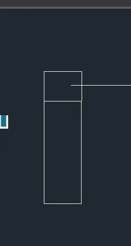
- Open AutoCad Selecting Imperial system Command UN(units) and selecting Engineering with precision of 0’-0.0”. Command LIMITS and having limit of (0’,0’) in lower left corner and (100’,100’) in upper right corner. Command ZOOM and selecting All. Changing the Workspace from Drafting and annotation to the 3D modelling.
- Wireframe modeling is useful for initial design iterations and as reference geometry, serving as a 3D framework for subsequent modeling or modification.
- Solid modeling is efficient to use, easy to combine primitives and extruded profiles, and offers mass properties and sectioning capabilities.
- Surface modeling offers fine control over curved surfaces for precise manipulation and analysis.
- Mesh modeling provides freeform sculpting, creasing, and smoothing capabilities.
- A 3D model can include combinations of these technologies, and you can convert between them. For example, you can convert a primitive 3D solid pyramid to a 3D mesh to perform mesh smoothing. You can then convert the mesh to a 3D surface or back to a 3D solid to take advantage of their respective modeling features.
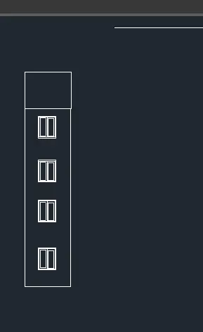
- Then with that point draw a rectangle using rectangle command using the dimensions of the rectangle as length is 2'6" and width is 2'6".
- by using the offset command in autocad make offsset of 2' for the side of a table ie enter the dimension of the offset as 2'.
- then select the last line of the rectangle and make offset of 2.5' ie the width of the both side of a table by using the offset command in autocad.
- Open AutoCad Selecting Imperial system Command UN(units) and selecting Engineering with precision of 0’-0.0”. Command LIMITS and having limit of (0’,0’) in lower left corner and (100’,100’) in upper right corner. Command ZOOM and selecting All. Changing the Workspace from Drafting and annotation to the 3D modelling.
- Wireframe modeling is useful for initial design iterations and as reference geometry, serving as a 3D framework for subsequent modeling or modification.
- Solid modeling is efficient to use, easy to combine primitives and extruded profiles, and offers mass properties and sectioning capabilities.
- Surface modeling offers fine control over curved surfaces for precise manipulation and analysis.
- Mesh modeling provides freeform sculpting, creasing, and smoothing capabilities.
- A 3D model can include combinations of these technologies, and you can convert between them. For example, you can convert a primitive 3D solid pyramid to a 3D mesh to perform mesh smoothing. You can then convert the mesh to a 3D surface or back to a 3D solid to take advantage of their respective modeling features.
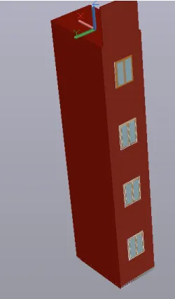
- of 0’-0.0”. Command LIMITS and having limit of (0’,0’) in lower left corner and (100’,100’) in upper right corner. Command ZOOM and selecting All. Changing the Workspace from Drafting and annotation to the 3D modelling.
- Wireframe modeling is useful for initial design iterations and as reference geometry, serving as a 3D framework for subsequent modeling or modification.
- Solid modeling is efficient to use, easy to combine primitives and extruded profiles, and offers mass properties and sectioning capabilities.
- Surface modeling offers fine control over curved surfaces for precise manipulation and analysis.
- Mesh modeling provides freeform sculpting, creasing, and smoothing capabilities.
- A 3D model can include combinations of these technologies, and you can convert between them. For example, you can convert a primitive 3D solid pyramid to a 3D mesh to perform mesh smoothing. You can then convert the mesh to a 3D surface or back to a 3D solid to take advantage of their respective modeling features
- Solid modeling is efficient to use, easy to combine primitives and extruded profiles, and offers mass properties and sectioning capabilities.
- Surface modeling offers fine control over curved surfaces for precise manipulation and analysis.
- Mesh modeling provides freeform sculpting, creasing, and smoothing capabilities.
- A 3D model can include combinations of these technologies, and you can convert between them. For example, you can convert a primitive 3D solid pyramid to a 3D mesh to perform mesh smoothing. You can then convert the mesh to a 3D surface or back to a 3D solid to take advantage of their respective modeling features
- Solid modeling is efficient to use, easy to combine primitives and extruded profiles, and offers mass properties and sectioning capabilities.
- Surface modeling offers fine control over curved surfaces for precise manipulation and analysis.
- Mesh modeling provides freeform sculpting, creasing, and smoothing capabilities.
- A 3D model can include combinations of these technologies, and you can convert between them. For example, you can convert a primitive 3D solid pyramid to a 3D mesh to perform mesh smoothing. You can then convert the mesh to a 3D surface or back to a 3D solid to take advantage of their respective modeling features
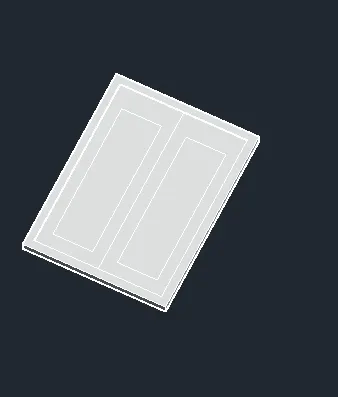
3. Aim: To Create the ismoteric 3d view of a stair with railing as shown in the plan and elevation. Assume the size of the balustrades and the hand rails.
procedure: The following steps should be followed as a procedure to draw a the ismoteric 3d view of a stair with railing as shown in the plan and elevation. Assume the size of the balustrades and the hand rails. given 3D using autocad
- To draw the given the ismoteric 3d view of a stair with railing as shown in the plan and elevation. Assume the size of the balustrades and the hand rails. in autocad, the following steps should be followed as a procedure. At first open the AutoCAD and set dimensions that the dimensions are in feets and inches.
- Then enter the Line command in AutoCAD and after that enter the first point of the given diagram as that line should be started at the point in the coordinate system.
- Then with that point draw a rectangle using rectangle command using the dimensions of the rectangle as length is 2'6" and width is 2'6".
- by using the offset command in autocad make offsset of 2' for the side of a table ie enter the dimension of the offset as 2'.
- then select the last line of the rectangle and make offset of 2.5' ie the width of the both side of a table by using the offset command in autocad.
- Open AutoCad Selecting Imperial system Command UN(units) and selecting Engineering with precision of 0’-0.0”. Command LIMITS and having limit of (0’,0’) in lower left corner and (100’,100’) in upper right corner. Command ZOOM and selecting All. Changing the Workspace from Drafting and annotation to the 3D modelling.
- To draw the 3d model table in autocad, the following steps should be followed as a procedure. At first open the AutoCAD and set dimensions that the dimensions are in feets and inches.
- Then enter the Line command in AutoCAD and after that enter the first point of the given diagram as that line should be started at the point in the coordinate system.
- Then with that point draw a rectangle using rectangle command using the dimensions of the rectangle as length is 2'6" and width is 2'6".
- by using the offset command in autocad make offsset of 2' for the side of a table ie enter the dimension of the offset as 2'.
- then select the last line of the rectangle and make offset of 2.5' ie the width of the both side of a table by using the offset command in autocad.
- Open AutoCad Selecting Imperial system Command UN(units) and selecting Engineering with precision of 0’-0.0”. Command LIMITS and having limit of (0’,0’) in lower left corner and (100’,100’) in upper right corner. Command ZOOM and selecting All. Changing the Workspace from Drafting and annotation to the 3D modelling.
- Then with that point draw a rectangle using rectangle command using the dimensions of the rectangle as length is 2'6" and width is 2'6".
- by using the offset command in autocad make offsset of 2' for the side of a table ie enter the dimension of the offset as 2'.
- then select the last line of the rectangle and make offset of 2.5' ie the width of the both side of a table by using the offset command in autocad.Open AutoCad Selecting Imperial system Command UN(units) and selecting Engineering with precision of 0’-0.0”. Command LIMITS and having limit of (0’,0’) in lower left corner and (100’,100’) in upper right corner. Command ZOOM and selecting All. Changing the Workspace from Drafting and annotation to the 3D modelling.
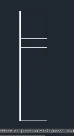
- To draw the 3d model table in autocad, the following steps should be followed as a procedure. At first open the AutoCAD and set dimensions that the dimensions are in feets and inches.
- Then enter the Line command in AutoCAD and after that enter the first point of the given diagram as that line should be started at the point in the coordinate system.
- Then with that point draw a rectangle using rectangle command using the dimensions of the rectangle as length is 2'6" and width is 2'6".
- by using the offset command in autocad make offsset of 2' for the side of a table ie enter the dimension of the offset as 2'.
- then select the last line of the rectangle and make offset of 2.5' ie the width of the both side of a table by using the offset command in autocad.
- To draw the 3d model table in autocad, the following steps should be followed as a procedure. At first open the AutoCAD and set dimensions that the dimensions are in feets and inches.
- Then enter the Line command in AutoCAD and after that enter the first point of the given diagram as that line should be started at the point in the coordinate system.
- Then with that point draw a rectangle using rectangle command using the dimensions of the rectangle as length is 2'6" and width is 2'6".
- by using the offset command in autocad make offsset of 2' for the side of a table ie enter the dimension of the offset as 2'.
- then select the last line of the rectangle and make offset of 2.5' ie the width of the both side of a table by using the offset command in autocad.
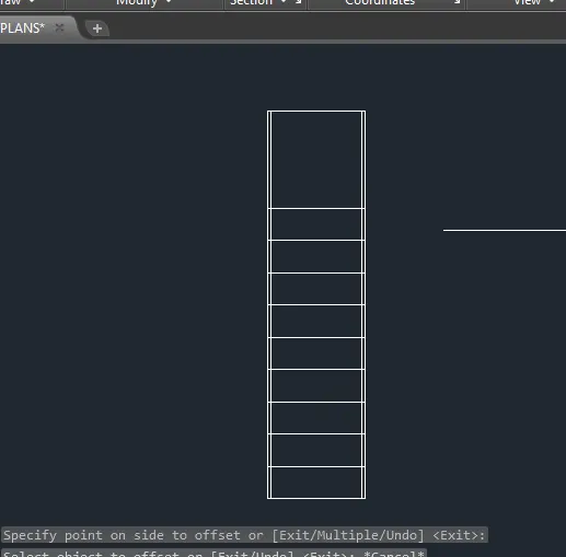
- Wireframe modeling is useful for initial design iterations and as reference geometry, serving as a 3D framework for subsequent modeling or modification.
- Solid modeling is efficient to use, easy to combine primitives and extruded profiles, and offers mass properties and sectioning capabilities.
- Surface modeling offers fine control over curved surfaces for precise manipulation and analysis.
- Mesh modeling provides freeform sculpting, creasing, and smoothing capabilities.
- A 3D model can include combinations of these technologies, and you can convert between them. For example, you can convert a primitive 3D solid pyramid to a 3D mesh to perform mesh smoothing. You can then convert the mesh to a 3D surface or back to a 3D solid to take advantage of their respective modeling features.
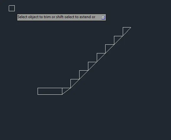
- Solid modeling is efficient to use, easy to combine primitives and extruded profiles, and offers mass properties and sectioning capabilities.
- Surface modeling offers fine control over curved surfaces for precise manipulation and analysis.
- Mesh modeling provides freeform sculpting, creasing, and smoothing capabilities.
- A 3D model can include combinations of these technologies, and you can convert between them. For example, you can convert a primitive 3D solid pyramid to a 3D mesh to perform mesh smoothing. You can then convert the mesh to a 3D surface or back to a 3D solid to take advantage of their respective modeling features
- Solid modeling is efficient to use, easy to combine primitives and extruded profiles, and offers mass properties and sectioning capabilities.
- Surface modeling offers fine control over curved surfaces for precise manipulation and analysis.
- Mesh modeling provides freeform sculpting, creasing, and smoothing capabilities.
- A 3D model can include combinations of these technologies, and you can convert between them. For example, you can convert a primitive 3D solid pyramid to a 3D mesh to perform mesh smoothing. You can then convert the mesh to a 3D surface or back to a 3D solid to take advantage of their respective modeling features
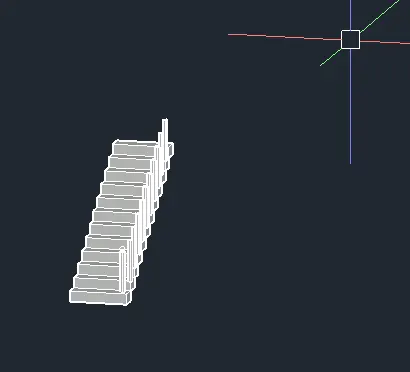
4. Aim: To Create the 3D view of a Wall with spread footing . Create the Door opening only. Assume the size of the parpaet and the coping. See the plans and elevation for the details. Also, create a rendered view of the model with materials as of your choice.
procedure: The following steps should be followed as a procedure to draw a the Create the 3D view of a Wall with spread footing . Create the Door opening only. Assume the size of the parpaet and the coping. See the plans and elevation for the details. Also, create a rendered view of the model with materials as of your choice.
- To draw the given Create the 3D view of a Wall with spread footing . Create the Door opening only. Assume the size of the parpaet and the coping. See the plans and elevation for the details. Also, create a rendered view of the model with materials as of your choice. in autocad, the following steps should be followed as a procedure. At first open the AutoCAD and set dimensions that the dimensions are in feets and inches.
- Then enter the Line command in AutoCAD and after that enter the first point of the given diagram as that line should be started at the point in the coordinate system.
- Then with that point draw a rectangle using rectangle command using the dimensions of the rectangle as length is 2'6" and width is 2'6".
- by using the offset command in autocad make offsset of 2' for the side of a table ie enter the dimension of the offset as 2'.
- then select the last line of the rectangle and make offset of 2.5' ie the width of the both side of a table by using the offset command in autocad.
- Open AutoCad Selecting Imperial system Command UN(units) and selecting Engineering with precision of 0’-0.0”. Command LIMITS and having limit of (0’,0’) in lower left corner and (100’,100’) in upper right corner. Command ZOOM and selecting All. Changing the Workspace from Drafting and annotation to the 3D modelling.
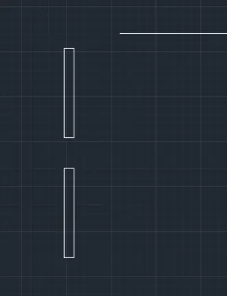
- Then enter the Line command in AutoCAD and after that enter the first point of the given diagram as that line should be started at the point in the coordinate system.
- Then with that point draw a rectangle using rectangle command using the dimensions of the rectangle as length is 2'6" and width is 2'6".
- by using the offset command in autocad make offsset of 2' for the side of a table ie enter the dimension of the offset as 2'.
- then select the last line of the rectangle and make offset of 2.5' ie the width of the both side of a table by using the offset command in autocad.
- Open AutoCad Selecting Imperial system Command UN(units) and selecting Engineering with precision of 0’-0.0”. Command LIMITS and having limit of (0’,0’) in lower left corner and (100’,100’) in upper right corner. Command ZOOM and selecting All. Changing the Workspace from Drafting and annotation to the 3D modelling.
- Then enter the Line command in AutoCAD and after that enter the first point of the given diagram as that line should be started at the point in the coordinate system
- Then with that point draw a rectangle using rectangle command using the dimensions of the rectangle as length is 2'6" and width is 2'6".
- by using the offset command in autocad make offsset of 2' for the side of a table ie enter the dimension of the offset as 2'.
- then select the last line of the rectangle and make offset of 2.5' ie the width of the both side of a table by using the offset command in autocad.
- Open AutoCad Selecting Imperial system Command UN(units) and selecting Engineering with precision of 0’-0.0”. Command LIMITS and having limit of (0’,0’) in lower left corner and (100’,100’) in upper right corner. Command ZOOM and selecting All. Changing the Workspace from Drafting and annotation to the 3D modelling.
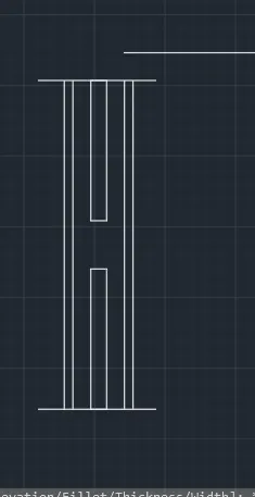
- by using the offset command in autocad make offsset of 2' for the side of a table ie enter the dimension of the offset as 2'.
- then select the last line of the rectangle and make offset of 2.5' ie the width of the both side of a table by using the offset command in autocad.
- Open AutoCad Selecting Imperial system Command UN(units) and selecting Engineering with precision of 0’-0.0”. Command LIMITS and having limit of (0’,0’) in lower left corner and (100’,100’) in upper right corner. Command ZOOM and selecting All. Changing the Workspace from Drafting and annotation to the 3D modelling.
- Then enter the Line command in AutoCAD and after that enter the first point of the given diagram as that line should be started at the point in the coordinate system
- Then with that point draw a rectangle using rectangle command using the dimensions of the rectangle as length is 2'6" and width is 2'6".
- by using the offset command in autocad make offsset of 2' for the side of a table ie enter the dimension of the offset as 2'.
- then select the last line of the rectangle and make offset of 2.5' ie the width of the both side of a table by using the offset command in autocad.
- Open AutoCad Selecting Imperial system Command UN(units) and selecting Engineering with precision of 0’-0.0”. Command LIMITS and having limit of (0’,0’) in lower left corner and (100’,100’) in upper right corner. Command ZOOM and selecting All. Changing the Workspace from Drafting and annotation to the 3D modelling.
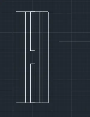
- by using the offset command in autocad make offsset of 2' for the side of a table ie enter the dimension of the offset as 2'.
- then select the last line of the rectangle and make offset of 2.5' ie the width of the both side of a table by using the offset command in autocad.
- Open AutoCad Selecting Imperial system Command UN(units) and selecting Engineering with precision of 0’-0.0”. Command LIMITS and having limit of (0’,0’) in lower left corner and (100’,100’) in upper right corner. Command ZOOM and selecting All. Changing the Workspace from Drafting and annotation to the 3D modelling.
- Then enter the Line command in AutoCAD and after that enter the first point of the given diagram as that line should be started at the point in the coordinate system
- Then with that point draw a rectangle using rectangle command using the dimensions of the rectangle as length is 2'6" and width is 2'6".
- by using the offset command in autocad make offsset of 2' for the side of a table ie enter the dimension of the offset as 2'.
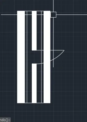
- by using the offset command in autocad make offsset of 2' for the side of a table ie enter the dimension of the offset as 2'.
- then select the last line of the rectangle and make offset of 2.5' ie the width of the both side of a table by using the offset command in autocad.
- Open AutoCad Selecting Imperial system Command UN(units) and selecting Engineering with precision of 0’-0.0”. Command LIMITS and having limit of (0’,0’) in lower left corner and (100’,100’) in upper right corner. Command ZOOM and selecting All. Changing the Workspace from Drafting and annotation to the 3D modelling.
- Then enter the Line command in AutoCAD and after that enter the first point of the given diagram as that line should be started at the point in the coordinate system
- Then with that point draw a rectangle using rectangle command using the dimensions of the rectangle as length is 2'6" and width is 2'6".
- by using the offset command in autocad make offsset of 2' for the side of a table ie enter the dimension of the offset as 2'.
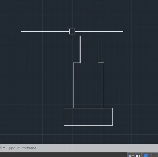
- Wireframe modeling is useful for initial design iterations and as reference geometry, serving as a 3D framework for subsequent modeling or modification.
- Solid modeling is efficient to use, easy to combine primitives and extruded profiles, and offers mass properties and sectioning capabilities.
- Surface modeling offers fine control over curved surfaces for precise manipulation and analysis.
- Mesh modeling provides freeform sculpting, creasing, and smoothing capabilities.
- A 3D model can include combinations of these technologies, and you can convert between them. For example, you can convert a primitive 3D solid pyramid to a 3D mesh to perform mesh smoothing. You can then convert the mesh to a 3D surface or back to a 3D solid to take advantage of their respective modeling features.
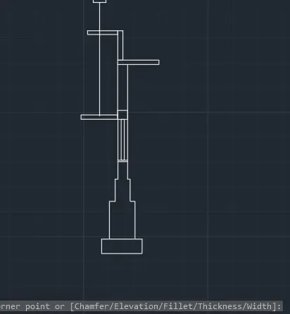
- Solid modeling is efficient to use, easy to combine primitives and extruded profiles, and offers mass properties and sectioning capabilities.
- Surface modeling offers fine control over curved surfaces for precise manipulation and analysis.
- Mesh modeling provides freeform sculpting, creasing, and smoothing capabilities.
- A 3D model can include combinations of these technologies, and you can convert between them. For example, you can convert a primitive 3D solid pyramid to a 3D mesh to perform mesh smoothing. You can then convert the mesh to a 3D surface or back to a 3D solid to take advantage of their respective modeling features
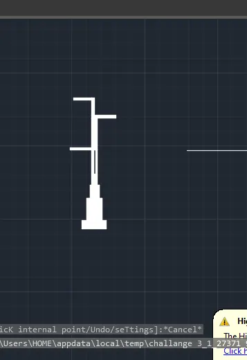
- Solid modeling is efficient to use, easy to combine primitives and extruded profiles, and offers mass properties and sectioning capabilities.
- Surface modeling offers fine control over curved surfaces for precise manipulation and analysis.
- Mesh modeling provides freeform sculpting, creasing, and smoothing capabilities.
- A 3D model can include combinations of these technologies, and you can convert between them. For example, you can convert a primitive 3D solid pyramid to a 3D mesh to perform mesh smoothing. You can then convert the mesh to a 3D surface or back to a 3D solid to take advantage of their respective modeling features
- Solid modeling is efficient to use, easy to combine primitives and extruded profiles, and offers mass properties and sectioning capabilities.
- Surface modeling offers fine control over curved surfaces for precise manipulation and analysis.
- Mesh modeling provides freeform sculpting, creasing, and smoothing capabilities.
- A 3D model can include combinations of these technologies, and you can convert between them. For example, you can convert a primitive 3D solid pyramid to a 3D mesh to perform mesh smoothing. You can then convert the mesh to a 3D surface or back to a 3D solid to take advantage of their respective modeling features
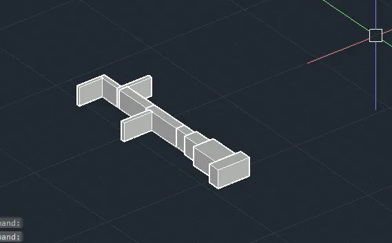
- The layer command is used to control and manage the drawings in AutoCAD for different purposes.
- It increases the display performance of the AutoCAD by hiding the portion of our drawing when needed. It also improves the visual complexity of the drawing.
- We are required to create a set of layers having different properties. For example, in a floor plan or house plan, we can create separate layers for doors, walls, etc.
- We can create many layers by specifying the name for the corresponding layer. We can also control the order of the layers.
- The shortcut command of the layer is 'LA'.
- Layer 0 is the default layer that exists in all drawings and has some esoteric properties. Instead of using this layer, it's best to create your own layers with meaningful names.
- Any drawing that contains at least one dimension object automatically includes a reserved layer named Defpoints.
- Create a layer for behind-the-scenes construction geometry, reference geometry, and notes that you usually do not need to see or print.
- Create a layer for layout viewports. Information about layout viewports is covered in the Layouts topic.
- Create a layer for all hatches and fills. This lets you to turn them all on or off in one action.