Creating 3D Isometric view of various structural elements in AutoCAD
AIM :
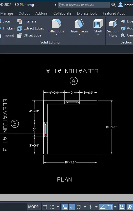
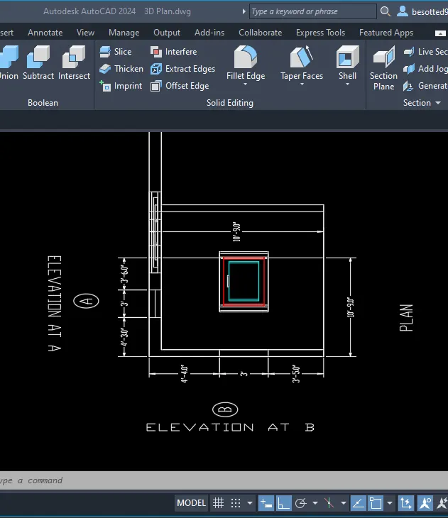
1. Create a 3D Isometric View of the building with plan and elevation.
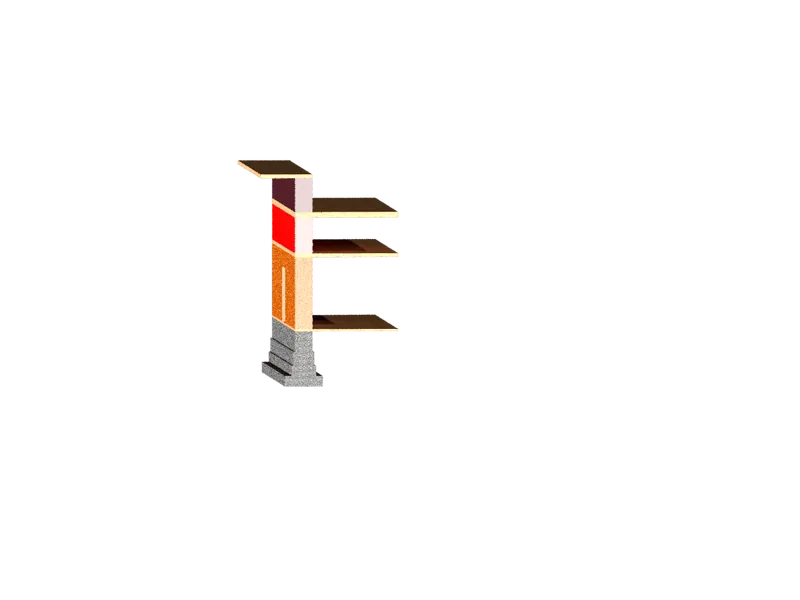
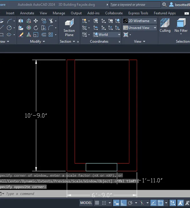
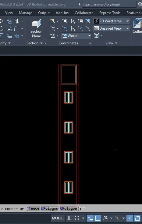
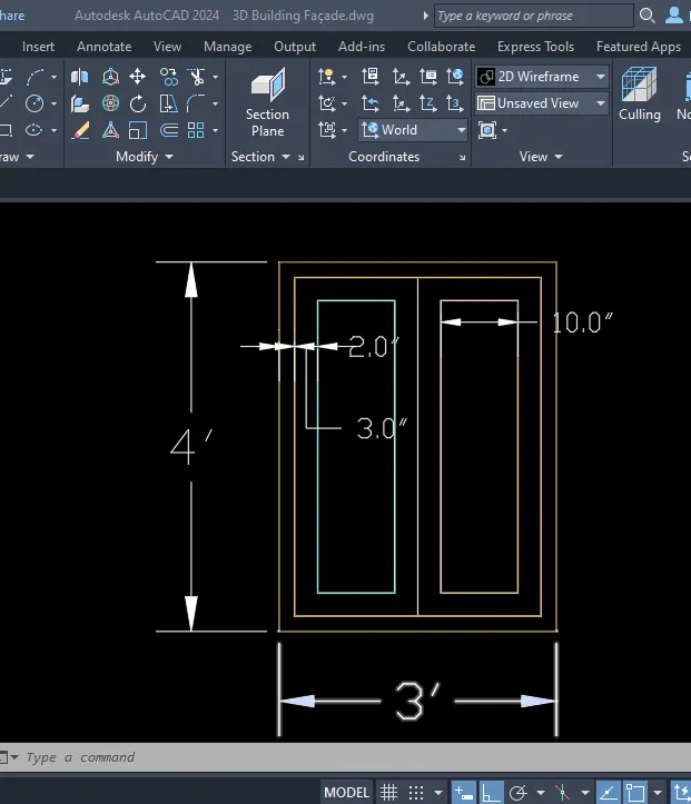
2. Create the 3D View of the Building Façade as given in the plan and elevation. Also, see the detail of the window.
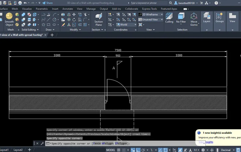
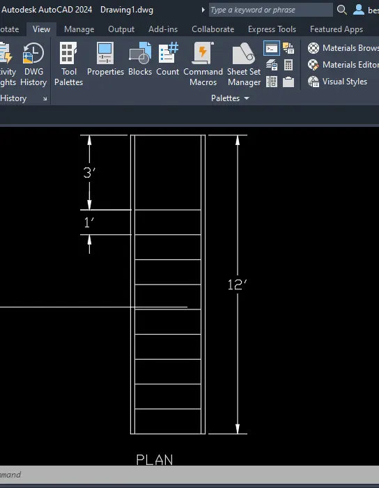
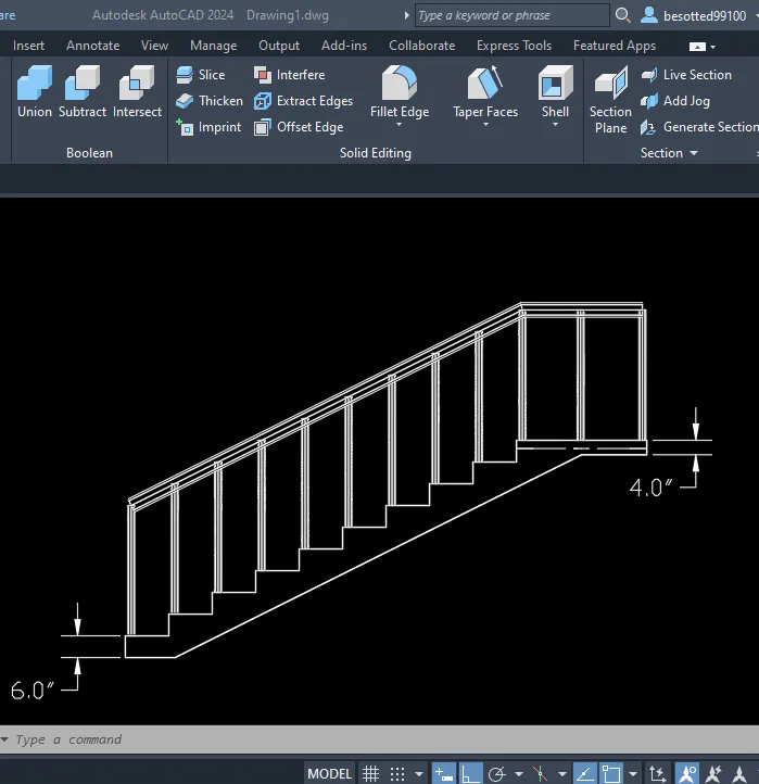
3. Create the ismoteric 3d view of a stair with railing as shown in the plan and elevation.
4. Create the 3D view of a Wall with spread footing.
INTRODUCTION :
The steps to setup AutoCAD for 3D are listed below:
1. Open the AutoCAD software.
2. On the status bar (present at the bottom of the screen), click on the Workspace Switching button, as shown below:
A drop-up list will appear, as shown below:
3. Click on the 3D Modeling option, as shown below:
We can also select a 3D Basics option from the drop-up list.
After that,
4. Change the Custom Model View to SE Isometric.
It gives the 3D view of an object. The other options, such as top, front, etc., shows the TOP and FRONT view of that object.
We can also change it to SW Isometric and can switch between other options accordingly.
It is shown below:
5. Change the Custom Visual Styles to Conceptual.
It is shown below:
We can switch between different styles according to the requirements.
6. Activate the Ortho and Polar mode on the status bar.
7. Adjust the UCS
All the above steps are necessary to implement before starting with 3D.
Isometic Drawing : Using Isometric commands is one of the simplest ways to give a 3-D representation while using only 2-D commands. Many times an isometric drawing is used to compliment or give more information to a 3 view orthographic drawing. AutoCAD has a command called ISOPLANE which allows you to easily draw at a 30 degree angle as needed for an isometric drawing. You can switch between the three 'isoplanes' (top, right, left) by using this command or by pressing the F5 key.
Command: ISOPLANE
Current isoplane: Right
Enter isometric plane setting [Left/Top/Right] : T
Current isoplane: Top
POLYLINE (PL) – The POLYLINE command will allow you to create a 2D polyline. When working with the Solid Model Tools, it is crucial to close a polyline when trying to make a shape. Not closing a polyline will result in a mesh object being created. Mesh objects are not recognized by the Solid Model Tools.
EXTRUDE (EXT) – The EXTRUDE command will extrude a 2D object into a 3D object. When using the EXTRUDE command, the original 2D object will be removed from the drawing.
PRESSPULL (PRESS) – The PRESSPULL command will extrude a 2D object into a 3D object, or extend a 3D surface. When using the PRESSPULL command with a 2D object, the 2D object will remain in the drawing.
BOX – The BOX command will allow you to create a 3D box by selecting 3 points in the X, Y, and Z axes.
3DMOVE (3M) – The 3DMOVE command will allow you to move an object in either the X, Y, or Z-axis.
3DROTATE (3R) – The 3DROTATE command will allow you to rotate an object about the X, Y, or Z axes.
3DPOLYLINE (3DPOLY) – The 3DPOLYLINE command will allow you to create a polyline with points that can exist in the X, Y, and Z axes.
UNION (UNI) – The UNION command will allow you to join separate 3D objects into one.
SUBTRACT (SU) – The SUBTRACT command will allow you to subtract 3D objects from another 3D object.
SLICE (SL) – The SLICE command will allow you to create a joint through a 3D solid.
PROCEDURE :
1. Step by Step procedure to create a 3D Isometric View of the building with plan and elevation.
- Open a new file: Control +N
- Click on Start from scratch & select imperial (metric)
- Enter Drawing unit(UN): UN [Enter]
- Enter Workspace Switching : WSCURRENT [Enter]
- Select 3-D Modelling
- Select View Cube in View ribbon
- Select Top in View Cube
- Enter RECTANGLE(REC) command: REC [Enter]
- Enter DIMENSIONS: D
- Enter EXTRUDE command : EXTRUDE [Enter]
- Enter 3D MIRROR command : 3DMIRROR [Enter]
- Enter 3D FACE command: 3DFACE [Enter]
- Enter HIDE command: HIDE [Enter]
- Complete the 3D Isometric View of the building with plan and elevation
2. Step by Step procedure to create the 3D View of the Building Façade as given in the plan and elevation. Also, see the detail of the window.
- Open a new file: Control +N
- Click on Start from scratch & select imperial (metric)
- Enter Drawing unit(UN): UN [Enter]
- Enter Workspace Switching : WSCURRENT [Enter]
- Select 3-D Modelling
- Select View Cube in View ribbon
- Select Top in View Cube
- Enter RECTANGLE(REC) command: REC [Enter]
- Enter DIMENSIONS: D
- Enter EXTRUDE command : EXTRUDE [Enter]
- Enter 3D MIRROR command : 3DMIRROR [Enter]
- Enter 3D FACE command: 3DFACE [Enter]
- Enter HIDE command: HIDE [Enter]
- Complete the 3D View of the Building Façade as given in the plan and elevation
3. Step by Step procedure to create the ismoteric 3d view of a stair with railing as shown in the plan and elevation.
- Open a new file: Control +N
- Click on Start from scratch & select imperial (metric)
- Enter Drawing unit(UN): UN [Enter]
- Enter Workspace Switching : WSCURRENT [Enter]
- Select 3-D Modelling
- Select View Cube in View ribbon
- Select Top in View Cube
- Enter RECTANGLE(REC) command: REC [Enter]
- Enter DIMENSIONS: D
- Enter EXTRUDE command : EXTRUDE [Enter]
- Enter 3D MIRROR command : 3DMIRROR [Enter]
- Enter 3D FACE command: 3DFACE [Enter]
- Enter HIDE command: HIDE [Enter]
- Complete the 3d view of a stair with railing as shown in the plan and elevation
4. Step by Step procedure to create the 3D view of a Wall with spread footing.
- Open a new file: Control +N
- Click on Start from scratch & select imperial (metric)
- Enter Drawing unit(UN): UN [Enter]
- Enter Workspace Switching : WSCURRENT [Enter]
- Select 3-D Modelling
- Select View Cube in View ribbon
- Select Top in View Cube
- Enter RECTANGLE(REC) command: REC [Enter]
- Enter DIMENSIONS: D
- Enter EXTRUDE command : EXTRUDE [Enter]
- Enter 3D MIRROR command : 3DMIRROR [Enter]
- Enter 3D FACE command: 3DFACE [Enter]
- Enter HIDE command: HIDE [Enter]
- Complete the 3D view of a Wall with spread footing
RESULT :
1. A 3D Isometric View of the building with plan and elevation.
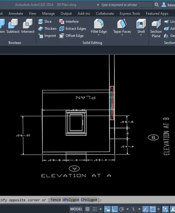
2. The 3D View of the Building Façade as given in the plan and elevation. Also, see the detail of the window.
3. The ismoteric 3d view of a stair with railing as shown in the plan and elevation.
4. The 3D view of a Wall with spread footing.