Creating 3D Isometric view of various structural elements in AutoCAD
QUESTION:
1. Create a 3D Isometric View of the building with plan and elevation given.
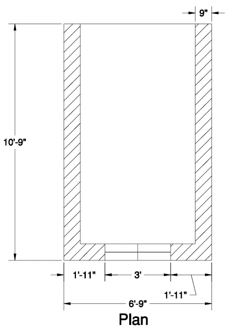
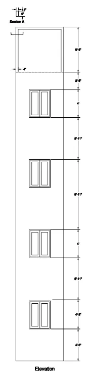
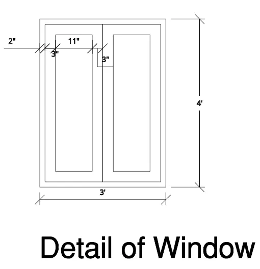
2. Create the 3D View of the Building Façade as given in the plan and elevation. Also, see the detail of the window.
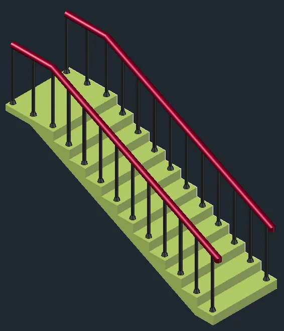
3. Create the ismoteric 3d view of a stair with railing as shown in the plan and elevation. Assume the size of the balustrades and the hand rails.
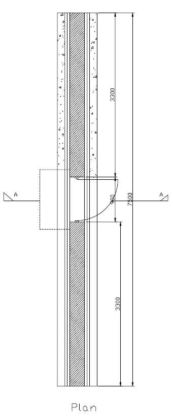
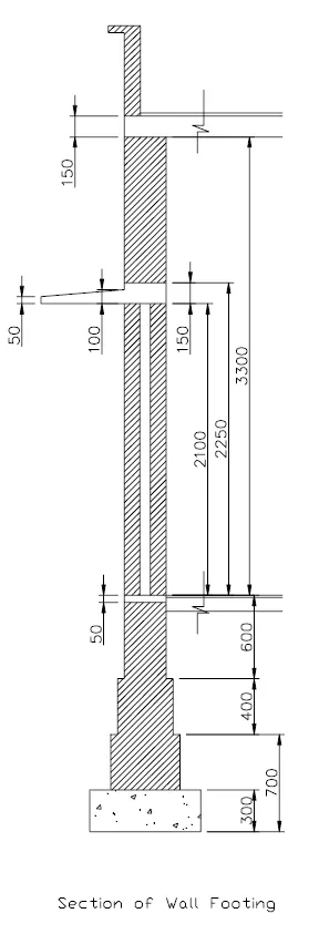
4. Create the 3D view of a Wall with spread footing . Create the Door opening only. Assume the size of the parpaet and the coping. See the plans and elevation for the details. Also, create a rendered view of the model with materials as of your choice.
AIM:
- To create a 3D Isometric View of the building with plan and elevation.
- To create the 3D View of the Building in the plan and elevation.
- To create the ismoteric 3d view of a stair with railing as shown in the plan and elevation.
- To create the 3D view of a Wall with spread footing.
INTODUCTION:
AutoCAD 3D is a three dimensional computer aided design, is technology for design and technical documentation, which replaces manual drafting with an automated process
Types of 3D models,
- Wireframe models
- Surface models
- Solid models
PROCEDURE:
Starting a AutoCAD software:
- Open Autocad software and click on START DRAWING.
- Set the units and length type by using 'UNITS' command.
- Set the limits by using 'LIMITS' command.
- Using 'ZOOM' command and select 'All' option
- Switch to 3D modelling on workspace.
- Use different tools and commands to create a given drawing.
- The above procedure use to given every drawings.
1. Create a 3D Isometric View of the building with plan and elevation given:
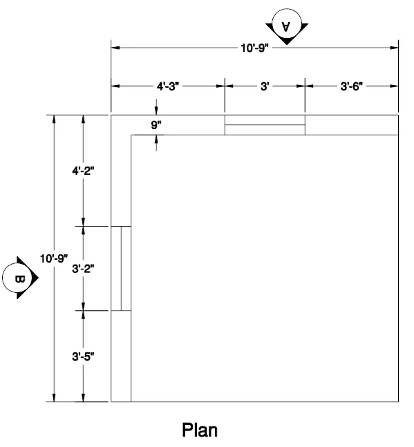
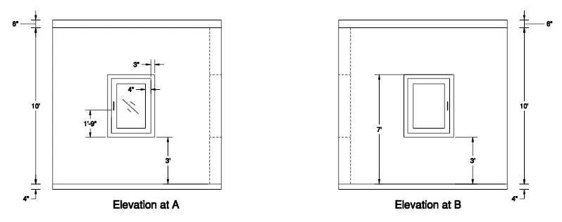
Step 1:
- Start a new layout and set the limits, units
- Change an workspace to 3d modelling
- Create a plan diagram at given dimension
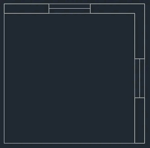
- Create a boundary and make the region
- EXTRUDE the created boundary layer
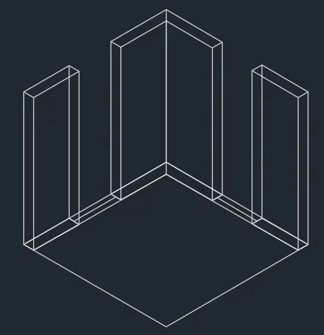
Step 2:
- Created a wall and make the layer to colour it
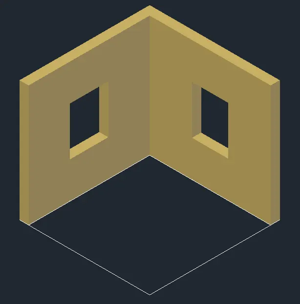
- Create the window at the sizess
- Then make a boundary region in the window
- Use SUBTRACT select a larger object and enter
- Then select the smaller object and enter to subtract it
- Repeated the same procedure to make window
Result:
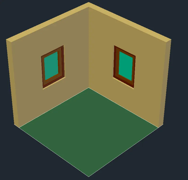
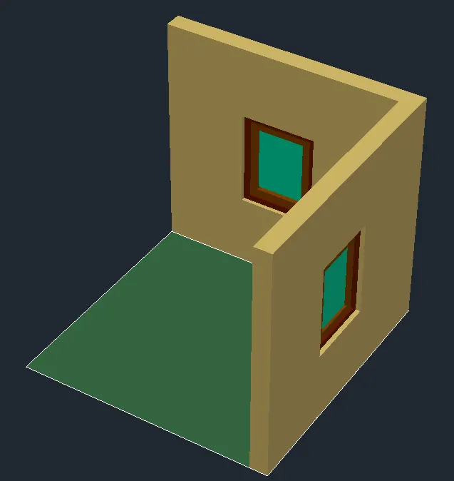
2. Create the 3D View of the Building Façade as given in the plan and elevation. Also, see the detail of the window:
Step 1:
- Start a new layout and set the limits, units
- Change an workspace to 3d modelling
- Create a plan at given dimension
- Using REC, LINE, OFFSET, TRIM option
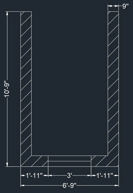
- EXTRUDE the plan and SUBTRACT the window space
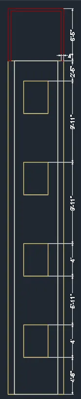
Step 2:
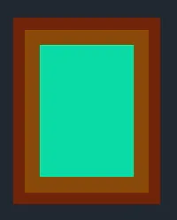
- Create the window at given detailed dimension
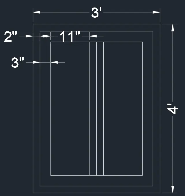
- Create the boundary and subtract a frame, mullion, glass
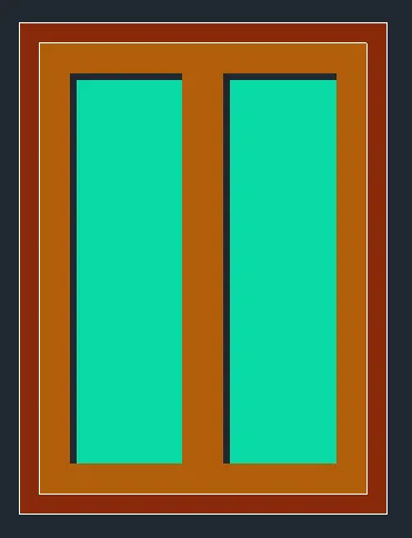
- Place the window at a desired place using COPY option

Result:
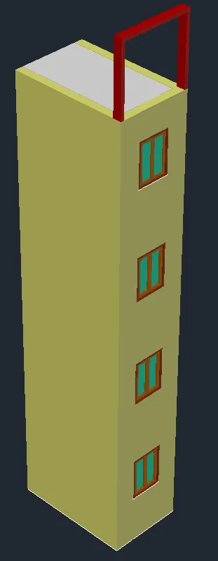
3. Create the ismoteric 3d view of a stair with railing as shown in the plan and elevation:
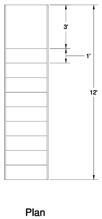
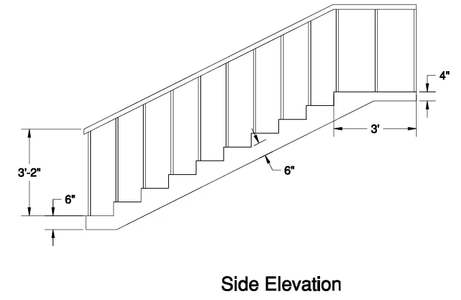
Step 1:
- Start a new layout and set the limits, units
- Change an workspace to 3d modelling
- Create a plant and section diagram
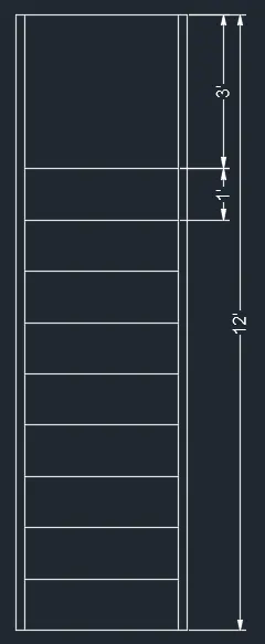
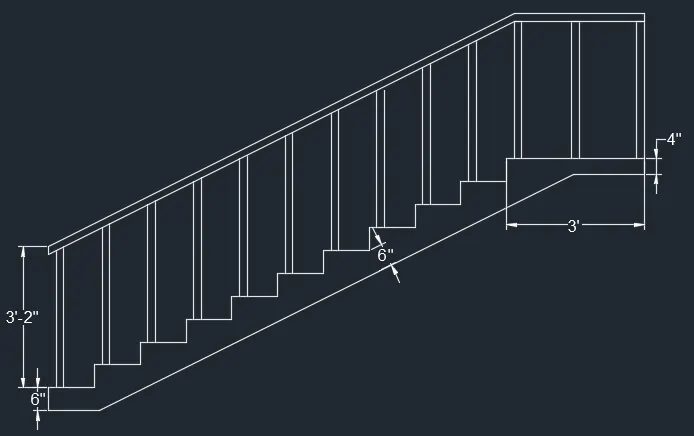
Step 2:
- EXTRUDE the stairs at a desired size
- Create a handrails and EXTRUDE it 3'
- Place the hand rail and copy to opposite side
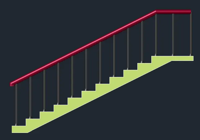
Result:
4. Create the 3D view of a Wall with spread footing:
Step 1:
- Start a new layout and set the limits, units
- Change an workspace to 3d modelling
- Create a plan and section from the given dimension
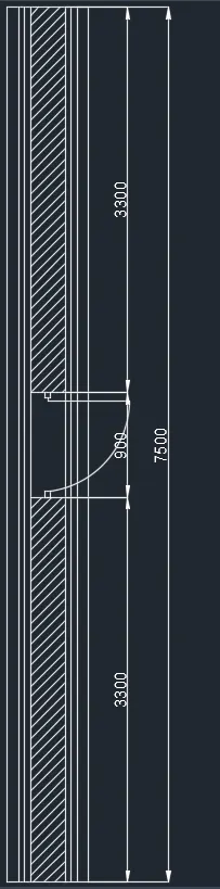
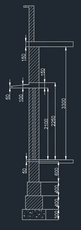
Step 2:
- EXTRUDE the section diagram at 7500
- Create the sunshade and SUBTRACT the door
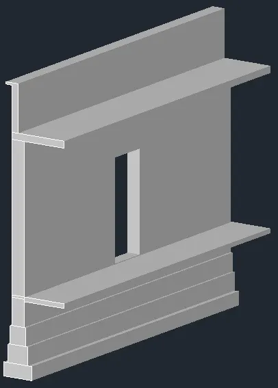
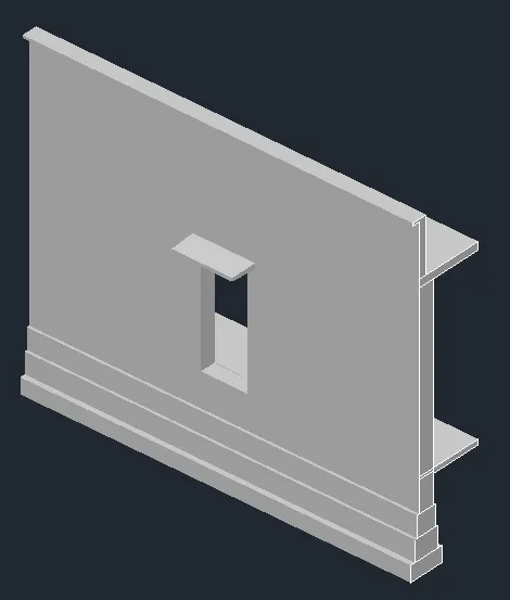
- Applied the 3d model material
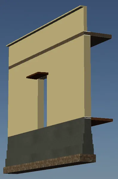
Result:
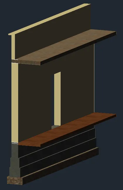
FINAL RESULT:
- The given plan and section diagrams are created in 3D models using AutoCAD
- All the final digrams are attached given below