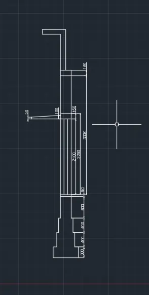
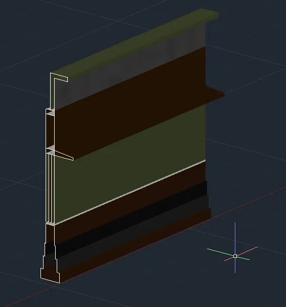
Creating 3D Isometric view of various structural elements in AutoCAD
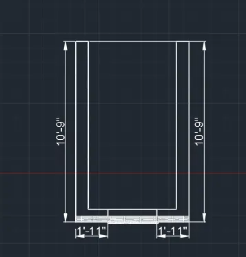
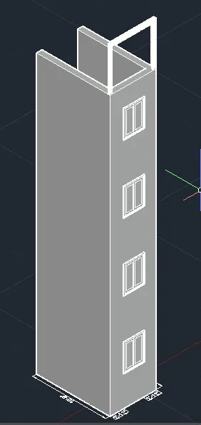
1. Aim: To create a 3D isometric view of the building with plan and elevation using autocad.
PROCEDURE:

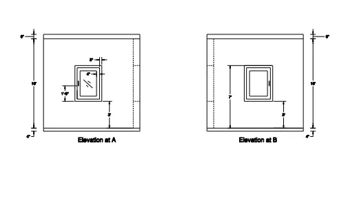
- In the command box type units and click on engineering-0'-0"
- In the command box type limits-0'0"
- In the command box type zoom-a
- Go to the top view
- In the command box type line and draw the lines of distance 10'-9",3',3'-2".
- In the command box type offset and offset of distance 9"
- In the command box type dim to give the dimensions.
- In the command box type extrude the walls.
- And draw the windows.
- Go to the shaded view
RESULT-
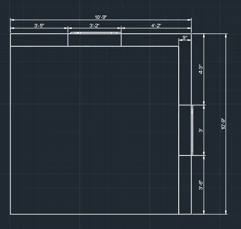
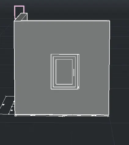
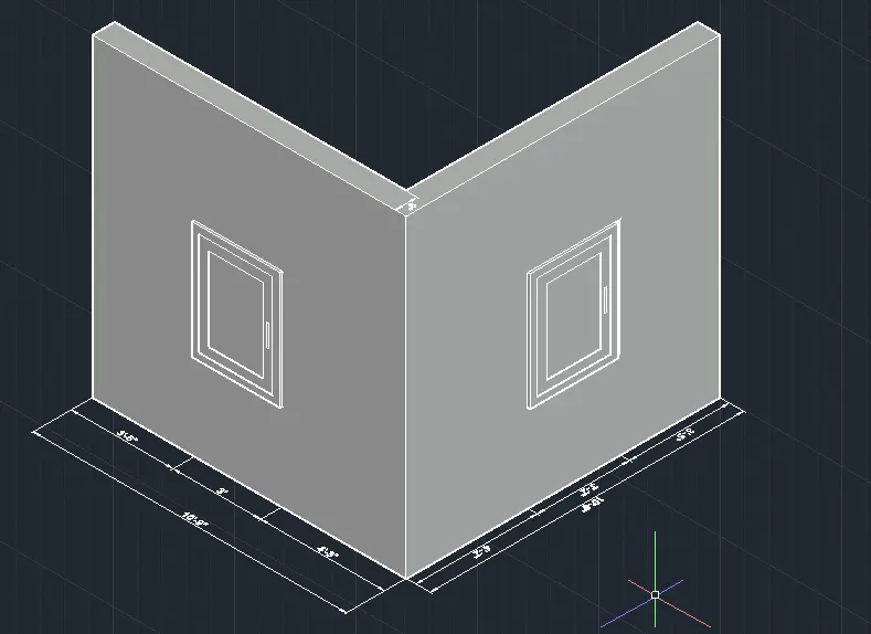
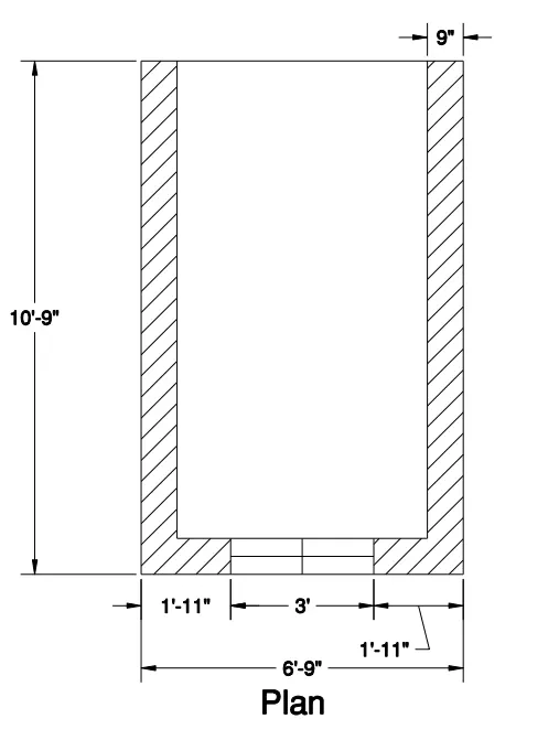
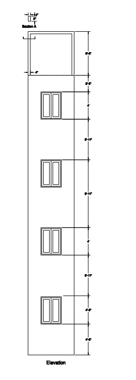
2. Aim: To create the 3D view of the building facade as given in the plan and elevation.
Procedure:
- In the command box type units and click on engineering-0'-0"
- In the command box type limits-0'0"
- In the command box type zoom-a
- Go to the top view
- In the command box type lines and draw the lines
- Draw a plan
- In the command box type dim and give the dimensions.
- n the command box type region and select the boundaries.
- In the command box type extrude
- And keep windows at required distance.
- GO to Shaded View.
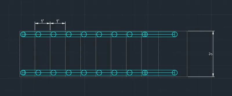
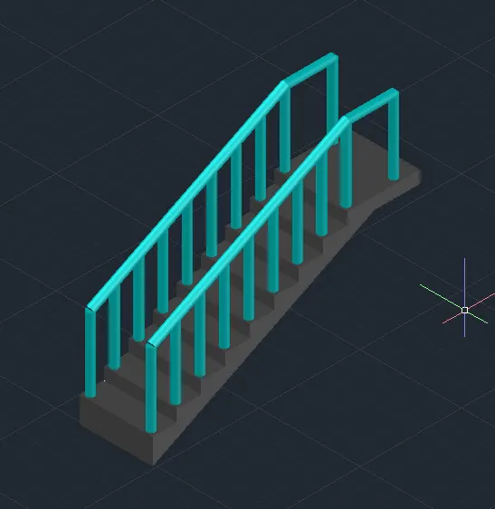
3. Aim: To create the isometric 3d view of the stair with a railing as shown in the plan elevatio using 3d autocad.
Procedure:
- In the command box type units and click on engineering-0'-0"
- In the command box type limits-0'-0'
- In the command box type zoom-a
- Go to the top view
- In the command box type line and draw the desired lines.
- Go to front view and create the tread and riser with the help of line command.
- In the command type dim to give the dimensions.
- Now go to southwest isometric view.
- In the command box type region
- Select the extrude for 3' distence
- In the command box type circle of dia 2" and click on sweep.
- And the circle is extrude for 3'-2"
- In the command box type line and join the ralings
- GO to Shaded View.
Result-
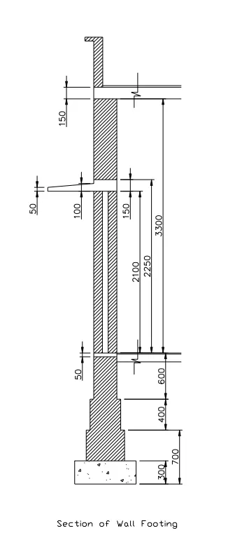
4. Aim: To create the 3D view of a wall with spread footing and to also create a door opening using AutoCAD.
Procedure:
- In the command box type units and click on engineering-0'-0"
- In the command box type limits-0'0"
- In the command box type zoom-a
- Go to the top view
- In the command box type line and draw the lines
- In the right view the plan is created.
- In the command box type dim to give the dimensions.
- Go to southwest isometric view.
- In the command box type extrude and extrude the plan.
- Go to view coomand and type material
- In the view select the material browsing.
- GO to Shaded View.
Result-