Creating 3D Isometric view of various structural elements in AutoCAD
Creating 3D Isometric view of various structural elements in AutoCAD
AIM: To Create 3D Isometric view of various structural elements in AutoCAD.
INTRODUCTION: Drawing are created in 3D isometric view of view control SE isometric.
Drawing No-1:
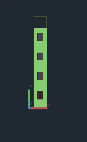
1. The 2D drawing are changed to 3D drawing with help of workspace settings to 3D modelling.
2. In 3D template Z-axis are introduced for protype drawing view.

3. Windows area walls are substracted with the tool substract and insert windows.
4. presspull tool is used to project in Z-axis.
5. Soild box used to create the 3D wall of the building.
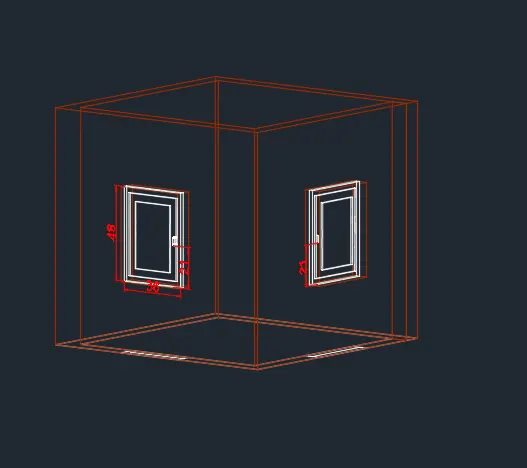
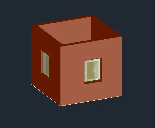
6. Materials are added to wall and windows.
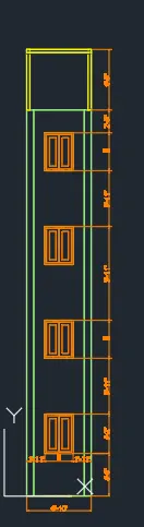
Drawing-2:
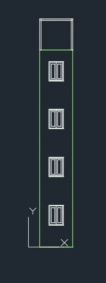
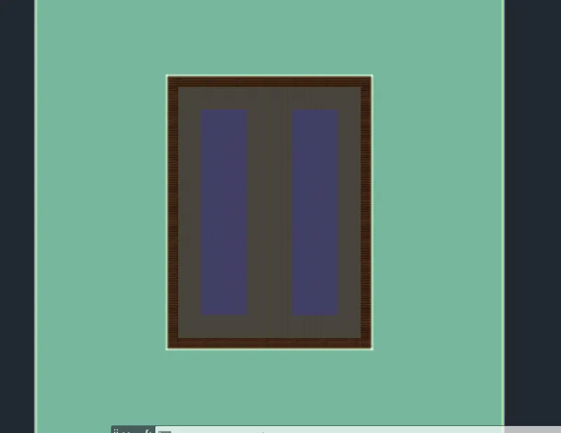
1. Building elevation are sketched with 3D modelling and added materials.
Drawing No-3:
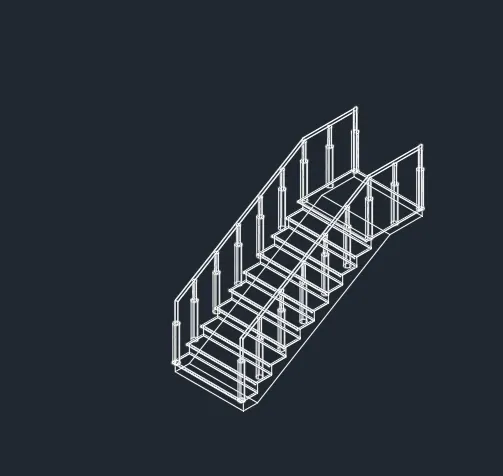
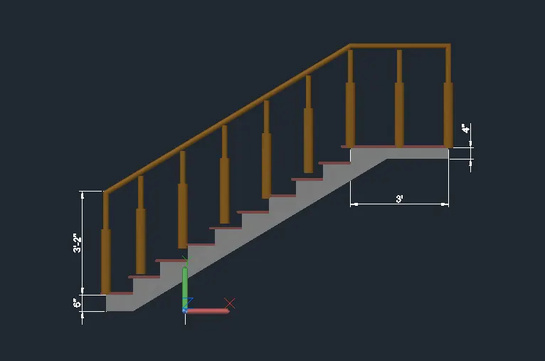
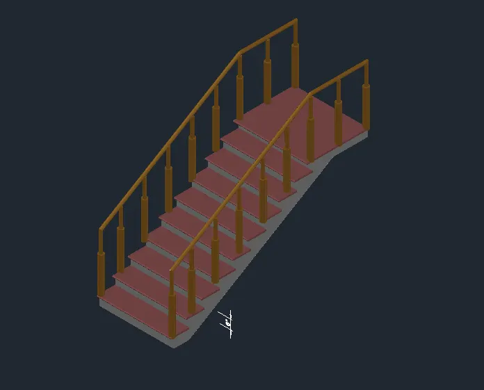
1. 3D stair case created and added railings with help of sweep tool.
2. Stair are presspulled with regular interval of 6" riser and 10" tread.
3. Railing are create with sweep tool by drawing polyline and circle.
4. Materials are textured in the 3D drawing.
Drawing No-4:
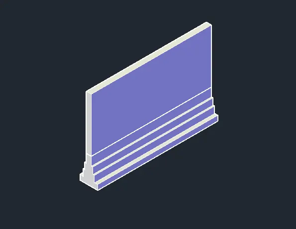
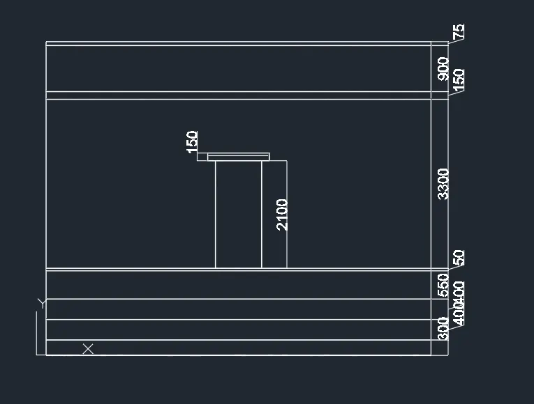
1. Footing,wall and door are created in 3D modeling.
2. Spread footing attached with 50mm DPC and wall with door are picturized in the 3D modelling template.
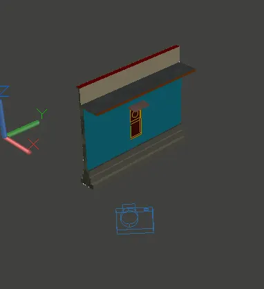
3. Door created and insert in the wall.
4. Materials are added to the elements.
5. Camera are fixed for the isometric view and adjusted lights and shadows.
6. Rendering are used to have the clear view of the 3D isometric sketch.
7. Rendering are used with high quality.
Result: Hence the isometric 3D view of the building,elevation with windows,3D stair case,and footing with wall and door are created with proper dimension as per the given data.