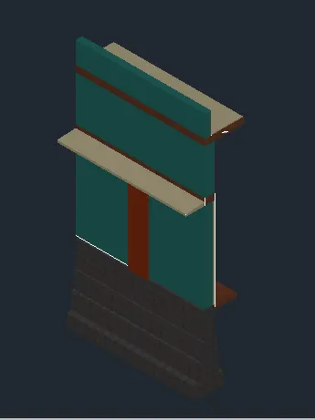
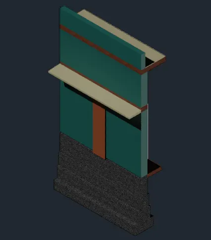
Creating 3D Isometric view of various structural elements in AutoCAD
AIM:Create a 3D Isometric View of the building with plan and elevation given.
INTRDOUCTION: The process of creating any surface of an object in three dimensions by using special TOOLS is called 3D modeling. A 3D model can also be represented as a two-dimensional image by using the 3D rendering process.
PROCEDURE:
PLAN-
- open autocad 2021 file.
- set the units as impherical(engineering).
- set the limits and zoom all.
- keep ortho and osnap on.
- go to setting displayed on right bottom panel-set 3d modeling.
- set the top view with wireframe.
- draw a rectangle of side 10'9".
- select the rectangle and explode.
- now offset the sides at distance 10" for making exterior wall.
- offset top wall line from left at distance 3'5" and 6'7"for making window.
- simialarly offset right at distance of 4'3" and 7'3".
- draw a center horizontal lines in offseted window portion.
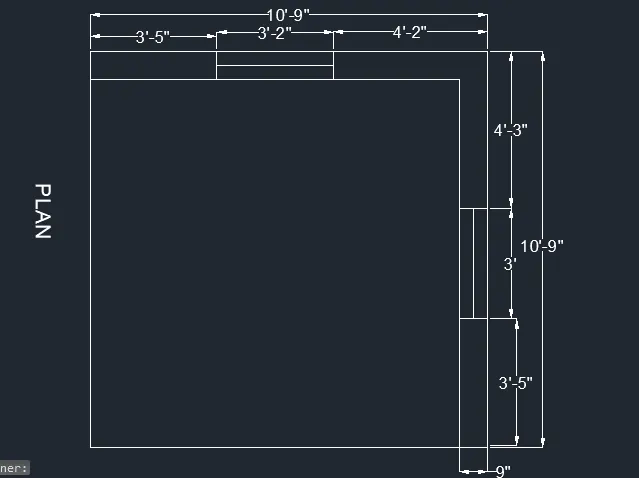
- now switch the view to SW isometric.
- make the wall section as region.
- extrude the wall upto 9' height.
- now select window rectangle and copy at distance 7' in z-axis using YCS icon for easy way.
- now extrude below window recatngle upto height 3' and above copied upto wall height.
SECTION-A-
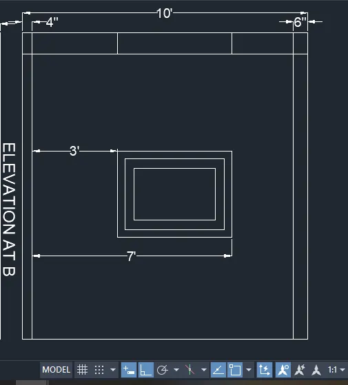
- draw a rcetangle of side 10'X10'9".
- explode the rectAngle.
- offset left side at distance 4"and eter to repeat the command offset right wall at distance 6".
- offset the bottom side at distance 9".
- for window making make a rectangle of diemnsion of 4'x3'.
- offset the rectangle at 3" and 7".
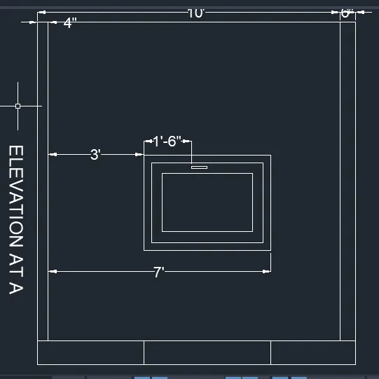
- move the window and place at center of plan at distance 3' from bottom.
- for making window handle,make a rectangle and move at distance 1'9" from window bottom.
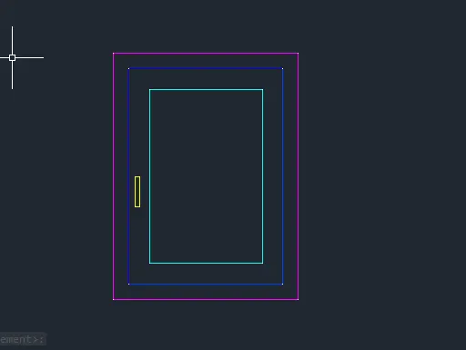
- now set to default view point,extrude the wall upto height 9'.
- now select window rectangle and copy at distance 7' in z-axis using YCS icon for easy way.
- now extrude below window recatngle upto height 3' and above copied upto wall height.
- extrude the window in y-axis at distance of wall thickness.
SECTION-B-
- follow same procedure to section A or change and 10" wall with window opposite to sec A.
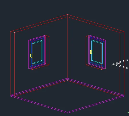
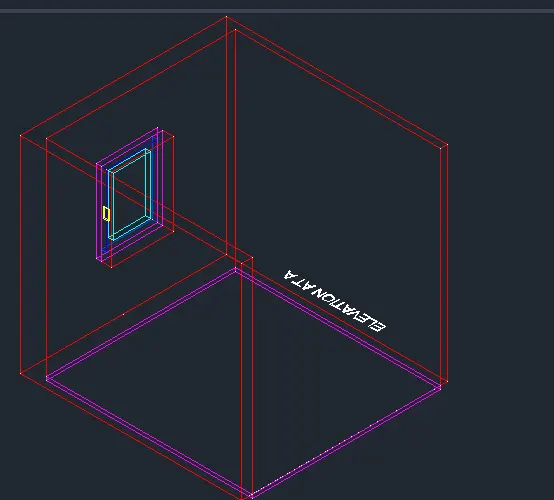
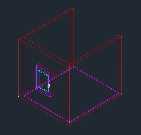
RESULT:
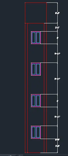
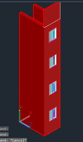
AIM: Create the 3D View of the Building Façade as given in the plan and elevation.
INTRODUCTION: given plan of building whoes diemnsion is 10'9"x6'9". It is G+3 building of overall height 40'7".
PROCEDURE:
- for plan section,draw a rectangle of dimension 10'9"x6'9".
- explode the rectangle.
- offset 3 sides with distance 9".
- draw a center vertical line in bottom wall and offset the at distnce 1'6" on both side.
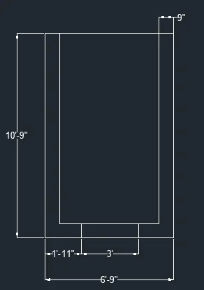
- set the view to SW isometric and make a region using boundary command.
- for making window,draw a rectangle of dmension 4'x3'.
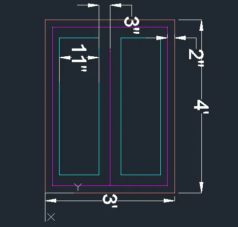
- offset the rectangle at distance 2" and 5".
- extrude the window at y ditsance of 9".
- for elevation,extrude the plan upto 40'10".
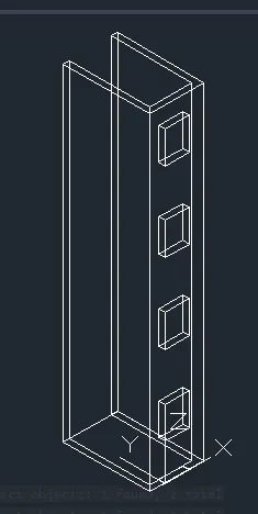
- copy the window at place at given distance using UCS or absolute coordinate system.
- for parapet wall,draw a recatngle of 4"x4" and extrude at height 6'5".
RESULT:
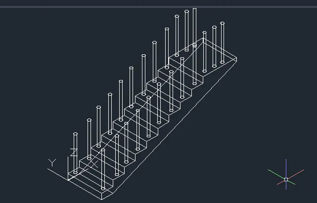
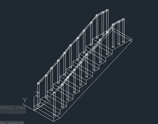
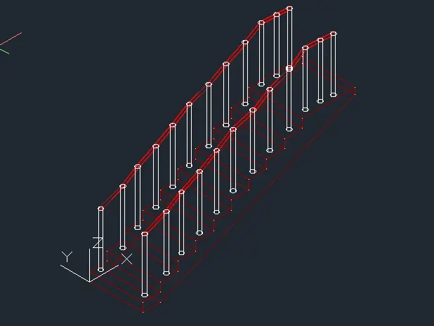
AIM:Create the ismoteric 3d view of a stair with railing as shown in the plan and elevation.
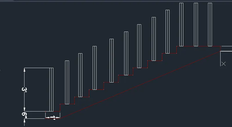
INTRDOCTION: given staircase of rise-6" and thread-1'.the railing height of stairs is 3'2" inclusing the handle which of 2" diameter.
here sweep option is used for making of handle for railing.
PROCEDURE:
- set the view to isometric.
- select line command and draw in XZ plan, 6'in z-axis and 1' in x-axis upto 10 steps.
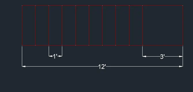
- extended the line upto 3' in x-axis and draw 4" in -z-axis.
- join the ends of stairs.
- select the lines are join them.
- use extrude command and 3' in Y-axis.
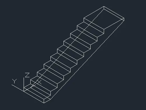
- for railing,set the view as top and draw a circle of 3" diameter.
- extrude the circle upto 3' and copy paste the same for next steps.
- use line command and alig the railing.
- draw a circle of 2" diameter.
- use sweep command,select circle and path as line joining rails.
RESULT:
AIM:Create the Door opening and Create the 3D view of a Wall with spread footing.
INTRDOUCTION: given plan of wall section with door of size 900x2100,with wall size 230. section of wall at center of plan,which showa isolated footting details.
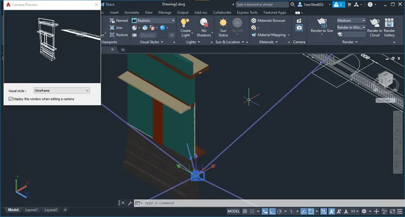
material browser present in visualize panel,from which materials required to the particular unit can be applied,it includes painiting,flooring,roofing etc.
Autocad 3d modeling main advantage is that ca se realistic view and can do rendering for picturaization of builiding in reality.
PROCEDURE:
- open the zutocad file,set the units to metric.
- set the limits to 0,0 and 10000,10000.
- zoom command and all enter.
- draw a rectangle of size 670x7500.
- explode the rectangle.
- draw a center vertical line and offset at distance 115 on wither side.
- offset the wall line at distance 50 twice on both side.
- offset horizontal line at distance 3300 and 4200.
- draw door using recatngle,line and arc command.
- now hatch the outer wall setting scale factor 50 and pattern ARC CONC.
- now hatch wall by pattern BRICK setting scale factor 200.
- use dimlinear to measure.
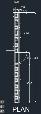
- to draw section AA which exactly cut at center of door.
- select polyline draw 335 in left direction,400 to top,120 to right,400 to top.
- next 50 to right,400 to top,50 to right,600 to top,3300 to top and 115 to right.
- select the ine and mirror the object to right.
- draw chajja at 2100 from footing top.
- draw parapet wall of thickness 150 on top.
- hatch the P.C.C bed using ARC-CONC scale factor at 25.
- hatch the section using ANS132.
- use inear dimension command.
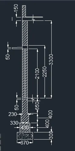
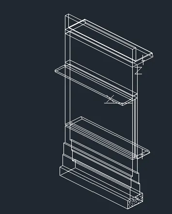
- set the view to isometric view,and extrude the section as shown below.
- select the material browerser.
- select the painting to wall,load to the document.
- select the wall and right click on material,assigN to the wall.
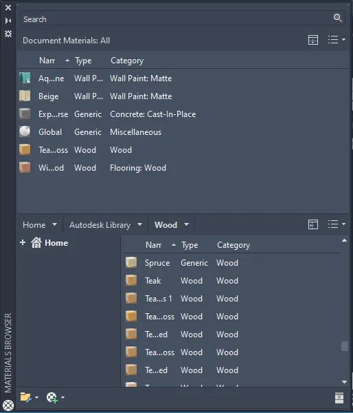
- repeat the same for remaining wall.
- to render,select create camera from visualize,set the camera view.
- save the view in view maneger.
- enter RR command,render the view or can define window.
RESULT: