Creating 3D Isometric view of various structural elements in AutoCAD
AIM: Create a 3D Isometric View of the building with the plan and elevation given.
INTRODUCTION: Create a 3D Isometric View of the building with the plan and elevation given. use the 3d tools while working.
PROCEDURE:
- open the auto cad file choosen the auto cad 3dmodeling work space,
- by using line created the walls plan on the universal ucs,
- later by using region command wall plan maked into region,
- by using extrude option selected the region, and extended upto 10',
- later that shifted the ucs to wall face created the rectangle with 3' x 4',
- by using the offsets frames are designed, and later by creating a region extruded from the rectangle,
- later that by using subtract command, select the wall next select the rectangle portion created the opening there and pasted the window by using a rectangle with offsets command,
- same rectangle is pasted in the other side also by using copy command after changing the UCS to the wall face,
- next by going to utilities. select the materials and select the objects assigned to respected portions.
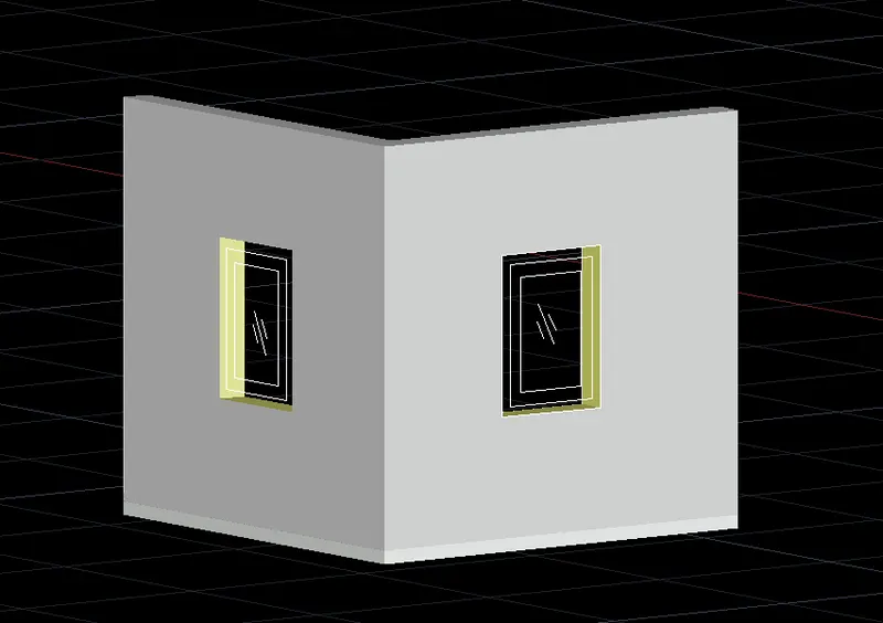
RESULT: Created a 3D Isometric View of the building with the plan and elevation given.
AIM: Create the 3D View of the Building Façade as given in the plan and elevation. Also, see the detail of the window.
INTRODUCTION: Create the 3D View of the Building Façade as given in the plan and elevation. Also, see the detail of the window. by using UCS, extrude, subtract, and 3mirrors commands also.
PROCEDURE:
- by seeing the plan the wall lines are created using the line command,
- later that make it region and extruded it upto one window level,
- next changed UC s to wall face in front created the rectangle outside of the plan with offsets as shown in window details,
- later that window is pasted on the wall surface at the 4'2" height and 1'1" from the corner,
- later by using copy options selected the whole drawing copied multiple times on top of the existing plan,
- by using extrude command extruded all windows later subtracted by the wall to window,
- by using the addition tool add the all walls,
- by using material command assigned the material to walls and windows.
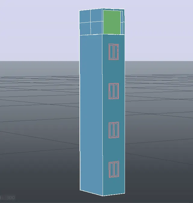
RESULT: Created the 3D View of the Building Façade as given in the plan and elevation.
AIM: Create the isometric 3d view of a stair with railing as shown in the plan and elevation. Assume the size of the balustrades and the hand rails.
INTRODUCTION: Create the ismoteric 3d view of a stair with railing as shown in the plan and elevation. Assume the size of the balustrades and the hand rails. by assming the handrail size 5' and using the sweep command rail runner created.
PROCEDURE:
- by using the line command created the profile of steps as rise 9" and thread is 1',
- like that for 10 steps profile created and later landing extended to 3',later landing slab thickness at edge is 4" on middle 6" provided,
- later using the region command all portions are region,
- by using extrude command, select the region extruded up to 3'2",
- by using the cylinder command created a cylinder at the top face of each step by using UCS on the step face,
- later that created a line at tops of cylinder, created small circle ,
- by using sweep command selected the circle and line enter the rail is created,
- view changed into shaded portion. clean the surface by using surface smooth option.
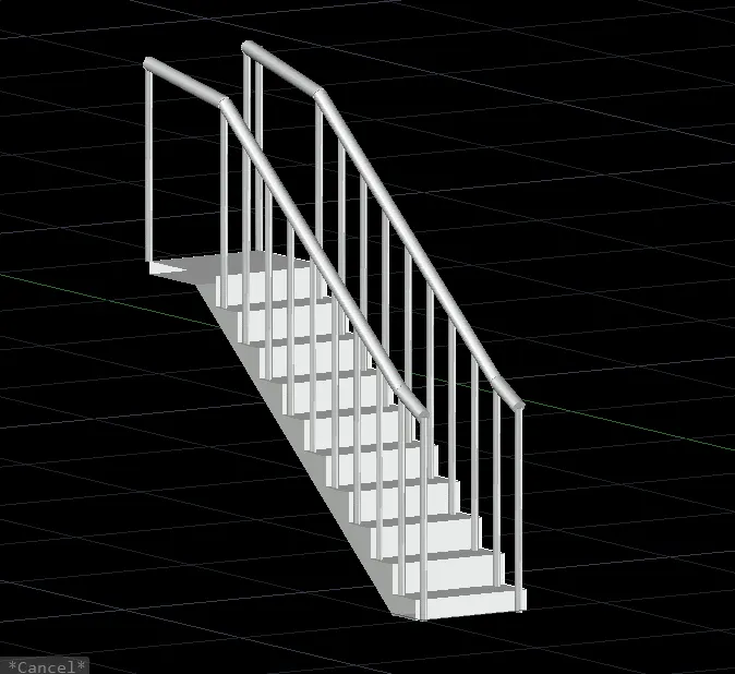
RESULT: Created the isometric 3d view of a stair with a railing as shown in the plan and elevation.
AIM: Create the 3D view of a Wall with spread footing . Create the Door opening only. Assume the size of the parpaet and the coping. See the plans and elevation for the details. Also, create a rendered view of the model with materials as of your choice.
INTRODUCTION: Create the 3D view of a Wall with spread footing . Create the Door opening only. Assume the size of the parpaet and the coping. See the plans and elevation for the details. Also, create a rendered view of the model with materials as of your choice. by usng rendering option the drawing is renderd.
PROCEDURE:
- by using the plan dimentions created the plan of elecvation by using polyline command,
- and make it region by using region command,
- busing extrude command all are extruded upto 7500mm,
- later that created the door with 2100 height ,900 width at side of plan, created the doors frames using the offsets,
- later door pasted at 3300 from the corner of wall,later by using extrude command extruded the whole door,
- using subtract command subtracted the wall from the door,
- later by using material command assigned the concrete to bottom layer,
- concrete surface with wall attached up to upto ground floor level,
- assigned the finished layer to the wall, glass material to door,wood material to frames,
- by using RR option created the sunlight for better view, set in hight render quality,enter the render option renderd the image, saved into JPG file.
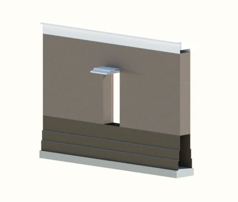
RESULT: Created the 3D view of a Wall with spread footing. Created the Door opening. Assume the size of the parapet and the coping. Also, created rendered view of the model with materials.