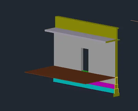
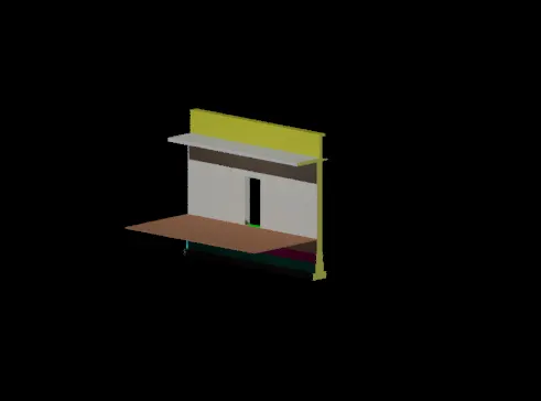
Creating 3D Isometric view of various structural elements in AutoCAD
1)
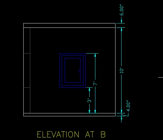
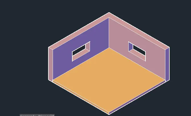
AIM: To create a 3D isometric view of the given building with plan and elevation given
INTRODUCTION: An isometric drawing is the 3d representation of the particular object. In an isometric drawing, the object appears as if it is being viewed from above one corner with the axes being set out from this corner point.
COMMANDS USED:
- Units
- Line
- rectangle
- UCS
- Polyline
- Dimlinear
- Region
- Extrude
- Subtract
- Box
- 3Dorbit
- Hide
- Explode
- Boundary
- Presspull
- Sweep
- Union
- 3D rotate
- Erase
PROCEDURE
- Open Autocad and set the units and limits
- Draw the rectangle using the rectangle command
- Draw the window of 3x9" and 9"x3'2"
- Draw the elevation of A and the elevation of B
- Draw the wall using the extrude command
- Use the layers for colouring
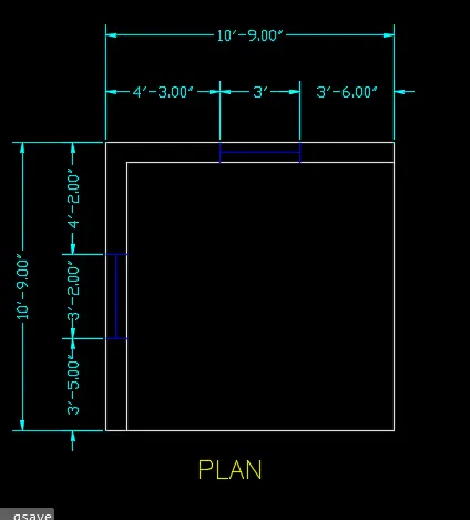
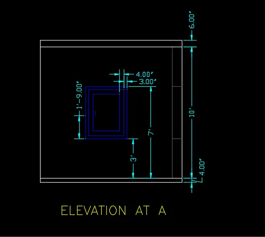
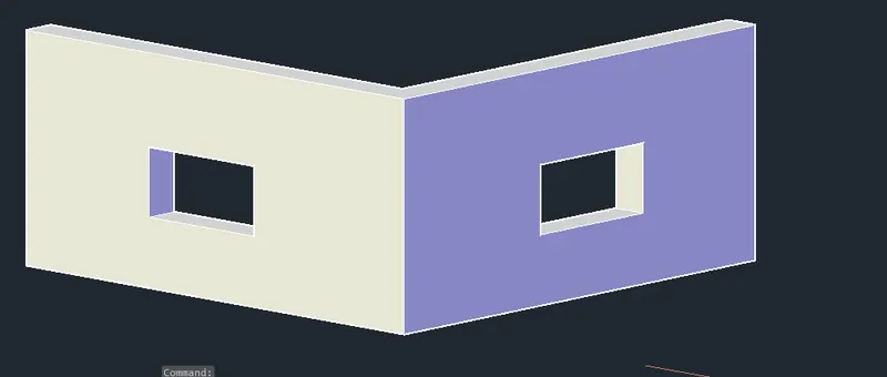
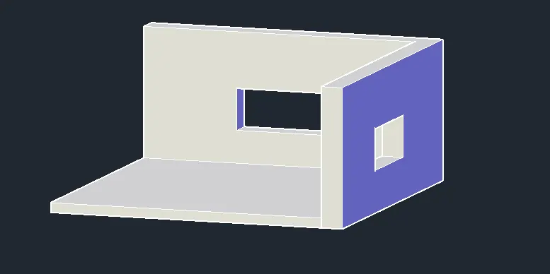
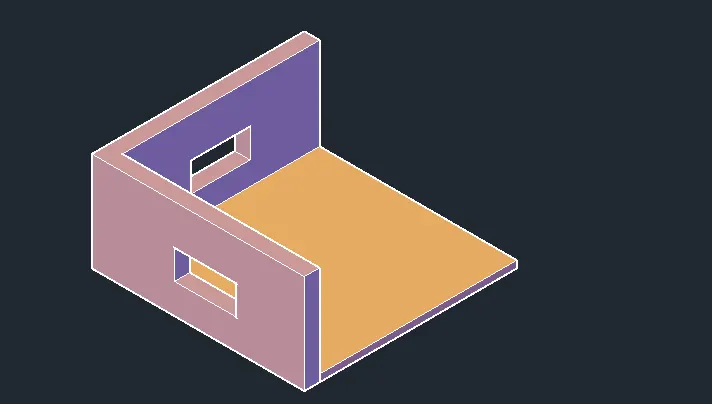
RESULT: The given 3d isometric view of the building is drawn
2)
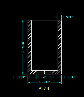
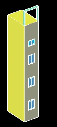
AIM: To create the 3D view of the building facade as per the given plan and elevation and need to create the window using the given dimension
PROCEDURE:
- Open the autocad file
- Set the limits and units
- Draw the rectangle by rectanglle command as per the given dimension
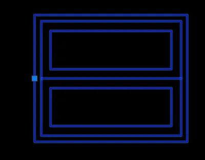
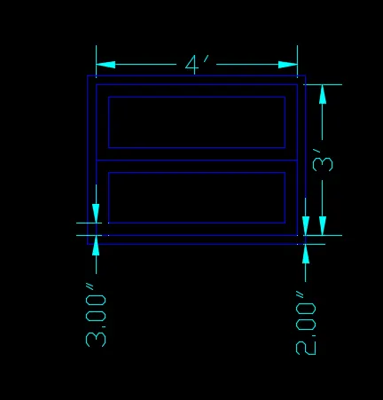
- Draw the window
- Use region command and select the object
- Extrude the plan using extrude command with the height of 40'10"
- Subtract the four windows vertically in a building facade with the distance 5'11" with the window size of 3'x4'
- Use the union command and select the objects
- select the custom visual style
- Command 3dorbit
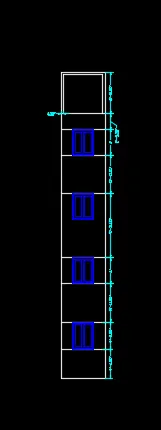
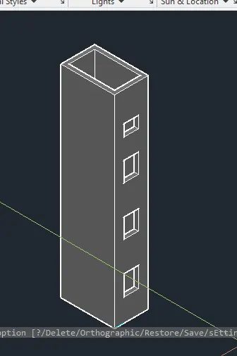
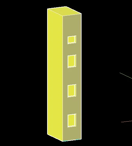
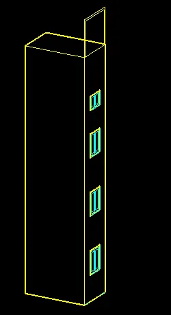
RESULT: Created the 3d isometric view of the building facade
3)
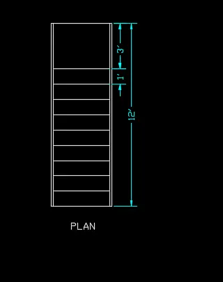
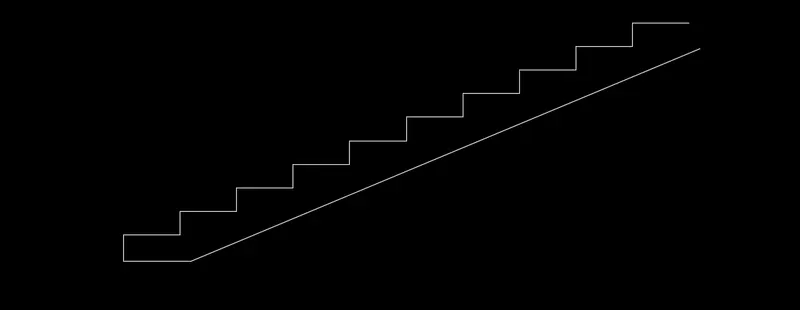
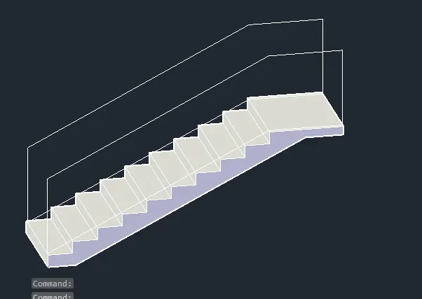
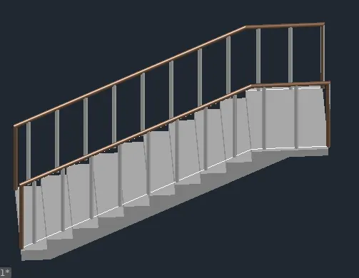
AIM: To create the isometric 3d view of a stair with railing as per the given plan and elevation
PROCEDURE:
- Open the autocad file
- Set the units, limits
- Change the view to front
- Draw the stairs with the riser of 6" and tread of 1'
- Command extrude 4'
- Draw the railing using circle command
- Command seep and select the object we get the railing
- Create a vertical post by circle command, extrude it
- Array the vertical post using the defined path
- Change the view to realistic
- Give the apt colour
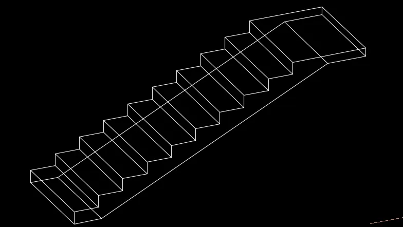
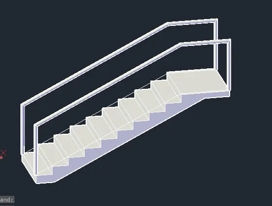
RESULT: The given isometric view of the stair is drawn
4)
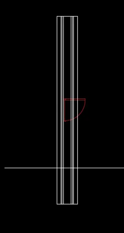
AIM: To create the 3D view of a wall with spread footing and need to create the rendered view of the model
PROCEDURE:
- Open the autocad new file
- Set the the units as decimal and the appropriate limits
- Provide the appropriate layers for working on it
- draw the section of wall with spread footing with the given dimension
- Command extrude and given value of 7500
- Provide the layers for the wall with spread footing with different colours for different parts
- Provide different materials for the wall
- Select the camera and put it in the position
- Select the render option and then changes to rendered view
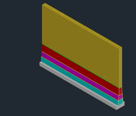
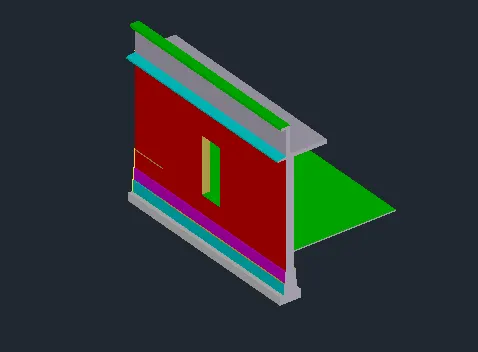
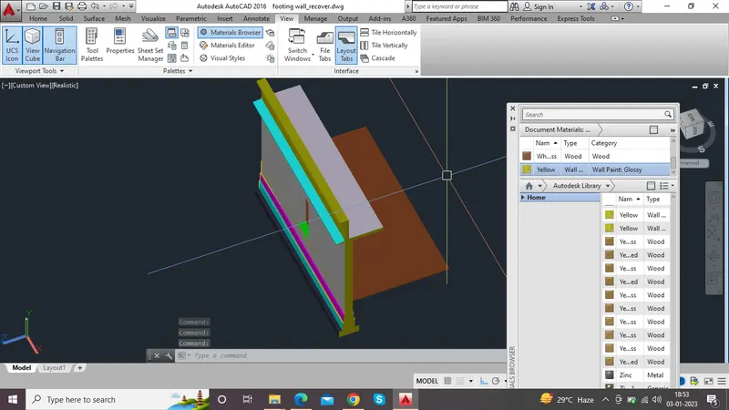
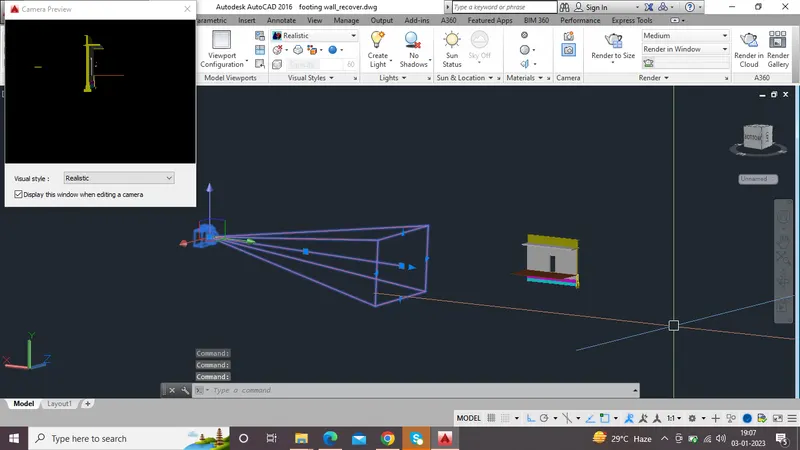
RESULT: Created the 3D view and rendered view of wall with spread footing