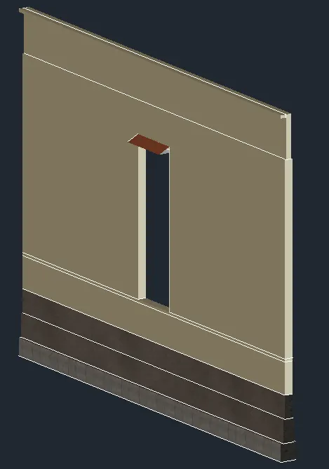
Creating 3D Isometric view of various structural elements in AutoCAD
Aim: To create a 3D Isometric View of the building with plan and elevation given.
Introduction: To create a 3D Isometric View of the building with plan and elevation given. By using AutoCad
Procedure:
Step1:
CRATION OF PLAN:
- Fist set the units and limits
- Create the 2d plan first as per given dimensions
- Then change the work space to the 3d modeling
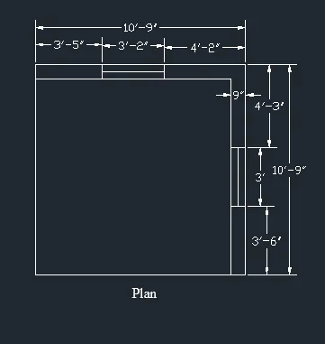
Step2:
- From ribbon > modeling > select the option presspull
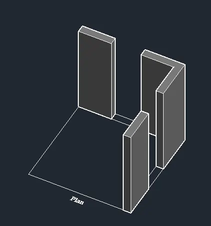
- Now keep the cursor in the close boundary it select the region then press it up and give the value as 10’ for the height of the wall
Step3:
- For the creation of window opening keep the cursor in window close boundary and give the height as 3’
- Now take the copy command and select the base point place it at the top point of the wall
- Now the opening for the window is done
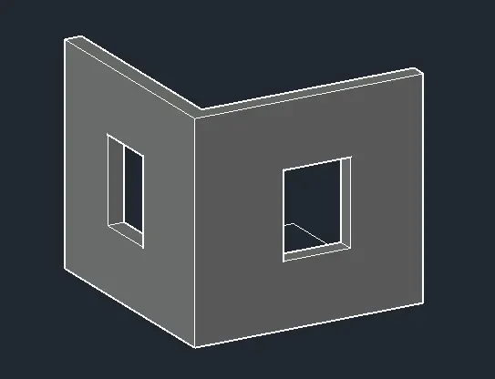
- Repeat the same process for the other side of the wall
Step4:
CEATION OF ELEVATION A:
- Create the 2d plan first as per given dimensions
- Then change the work space to the 3d modeling as given
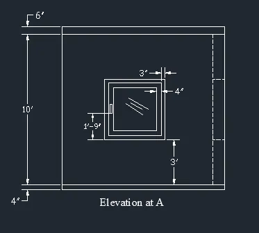
Step5:
- Frist create the window in take the rectangle of 3’
- Next take the offset command give the offset of 3” and next 4” use the press and pull command
- Now select the go to the property and give the colour
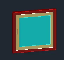
Step6:
- Now select the window take the move command select the base point and place in the open space the window as shown
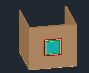
Step7:
CEATION OF ELEVATION B:
- Create the 2d plan first as per given dimensions
- Then change the work space to the 3d modeling as given
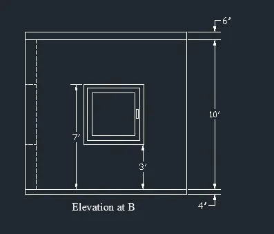
Step7:
- Select the copy window in as created in above step
- Now select the window take the move command select the base point and place in the open space the window as shown
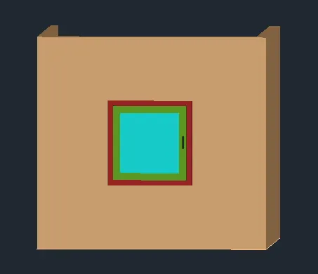
Result:
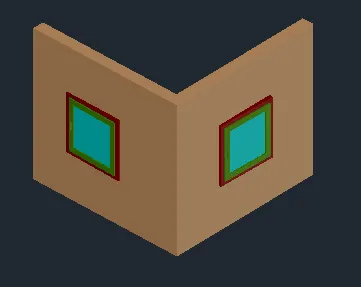
2):
2):
Aim: To create the 3D View of the Building Façade as given in the plan and elevation.
Introduction: To create the 3D View of the Building Façade as given in the plan and elevation. By using AutoCAd
Procedure:
Step1:
CRATION OF PLAN:
- Fist set the units and limits
- Create the 2d plan first as per given dimensions
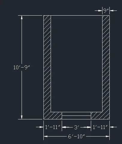
Step2:
- Then change the work space to the 3d modeling

Step4:
- From ribbon > modeling > select the option presspull
- Now keep the cursor in the close boundary it select the region then press it up and give the value as as per given the elevation plan for the height of the wall
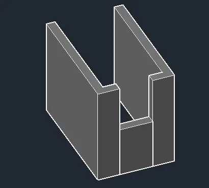
Step5:
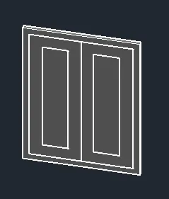
- Frist create the window in take the rectangle of 4’
- Next take the offset command give the offset of 1” for the creation of window frame and next from the top coner point draw a rectangle in the mid and take the offset of 4” use the press and pull command
Step6:
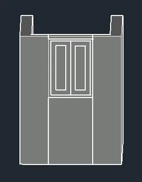
- Placing of window take the command move select the object give the base point and place it at position
Step7:
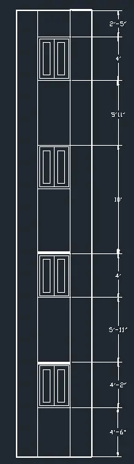
- Repeat the same process for all floor up to the top of the building
- Change the view to front view next take the command DIML and give the dimensions as shown
Step8:
- Creation of top section of the building
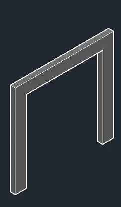
- Take a line command and draw a vertical of 6’5” and draw a another line in horizontal x axis next give the offset of 9”
Step9:
- Now take the move command select the object give the base point place the object as shown
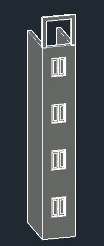
Step10:
- Adding of materials to the objects
- Take the command MAT > home > wall paint select the object assessing the property to the selected object add paint to the walls as per requirement
- Next go the wood option and add wood property to the windows
- Next add glass property to the to glass of the windows
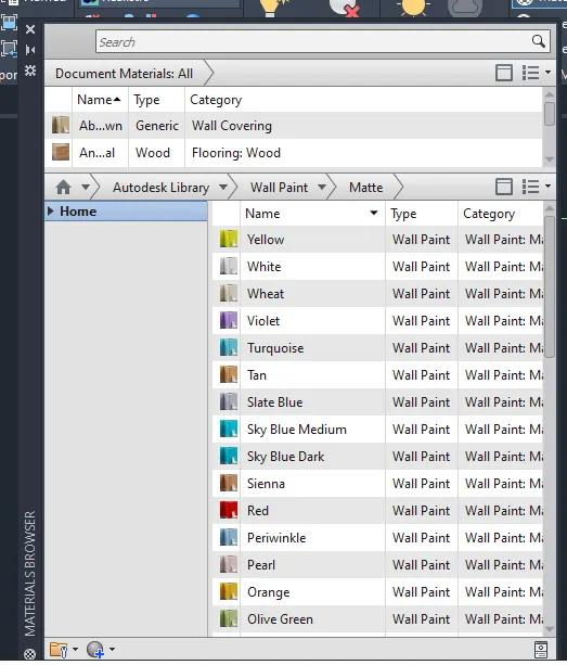
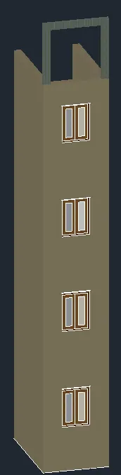
Step11:
- From the ribbon > visuals > take the camera set the location of the camera and focus target of object as shown
- Next go to rendering option and rendering
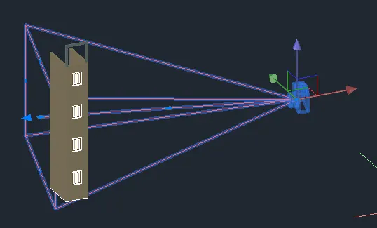
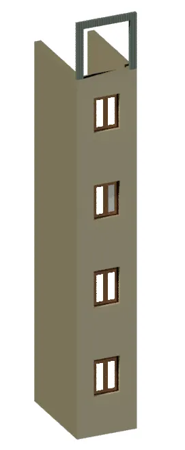
Result:
3):
Aim: To create the ismoteric 3d view of a stair with railing
Introduction: To create the ismoteric 3d view of a stair with railing. By using AutoCad
Procedure:
Step1:
- First take the line command draw a line for riser is 6” and trade is 1’ as shown
Step2:
- Now take the copy command give the base point copy the steps one an above as shown
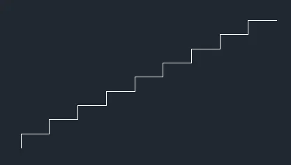
Step3:
- From the last step draw a line of 3’ for the landing and give the 6” of thickness for the landing and waste slab
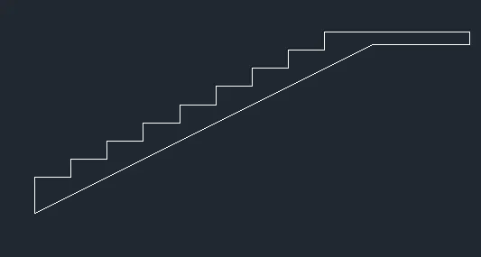
Step4:
- Take dim command and give the dimension as per given plan
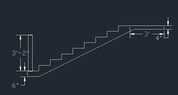
Step5:
- Now rotated the object by using the command “ro3d” rotated in the 90 degree
- Next take the presspull and give the width as 3’ for staircase
- Now change the view from visual style control to shades of grey
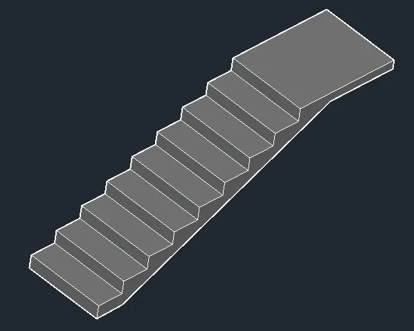
Step6:
- Creation of railings
- Draw a circle by using command c of 2” and then take the presspull option from the ribbon and give the height as 3’2”
- Next take the copy command select the base and copy the railing step by step
- Now take the line and draw a line passing through all top of all the railings
- Next draw a circle of 1” and take the command sweep select the circle and select the line
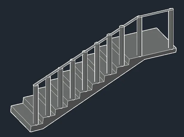
Step7:
- Now take the command “mat” for assign the property to the objects
- Take the colour for steps and give metallic property for railing
- While assign the property to object keep the view in realistic
- Then go for rendering for finishing of object
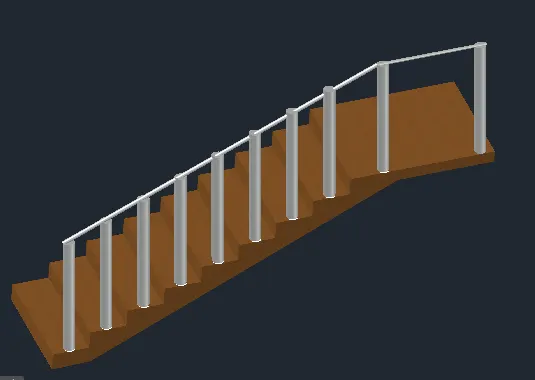
Result:
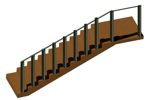
4):
Aim: To create the 3D view of a Wall with spread footing
Introduction: To create the 3D view of a Wall with spread footing. By using AutoCad
Procedure:
Step1:
CRATION OF PLAN:
- Fist set the units and limits
- Create the 2d plan first as per given dimensions
- Frist set the limits and unit
- Take the line draw a line of 7500mm in y axis and give width 230mm
- Next the offset of 50mm on the side repeat the offset 25mm on both side and again take the offset of 300mm on both side total is 600mm
- For the opining of the door in the wall mark a vertical of 3300mm from the top and bottom
- The oping for the door is created as 90mm as shown
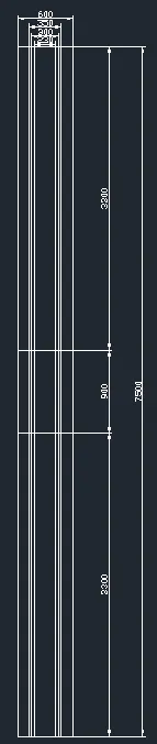
Step2:
- Now take the hatch command and provide hatch ANS132 for wall and ARCON for footing
- Next take the DIML command for dimension select the first point and end point for measuring the dimensions as shown
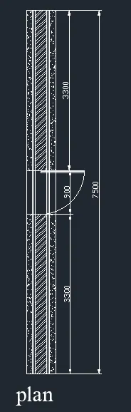
Step3:
- Now change the workspace to 3d modeling
- Take the presspull from the ribbon and give the height of 300mm
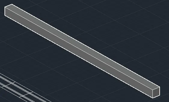
Step4:
- Draw another rectangle above it and give the height as 400mm total 700mm as per given in plan
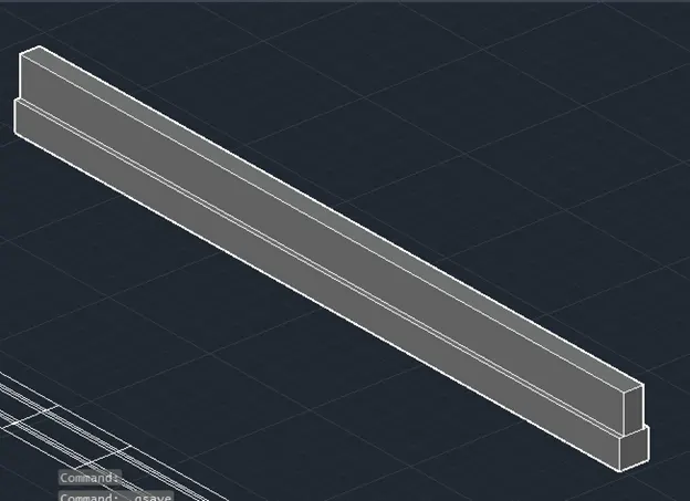
Step5:
- Draw another rectangle above it and give the height as 6000mm with cover of 50mm for lintel level
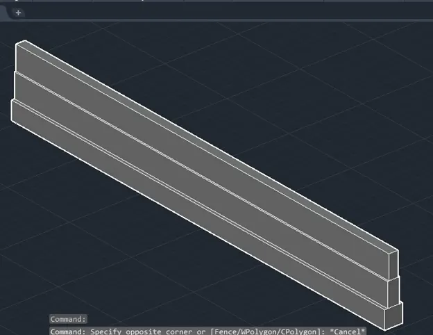
Step6:
- Now take the presspull command keep the cursor in the close boundary and give the height as 3300mm as height of the given wall
- Opining for the door is provided as 900m and rest of the wall height is given as 330mm as shown in
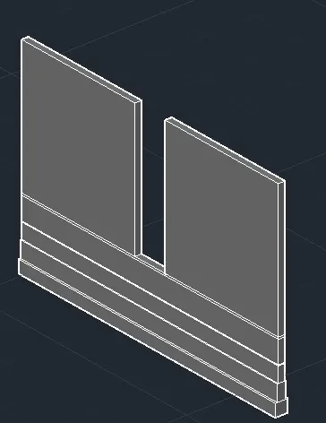
Step7:
- Height of the door is given as 2100mm and from the lintel is 2250 after take presspull and join the remain part to height of wall
- Creating shade draw horizontal of 100mm and next draw a midline and join it at 50mm
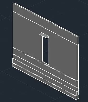
Step8:
- Providing the dimensions
- Take the command Next take the DIML command for dimension select the first point and end point for measuring the dimensions
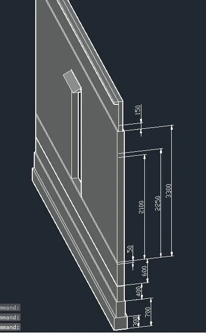
Step9:
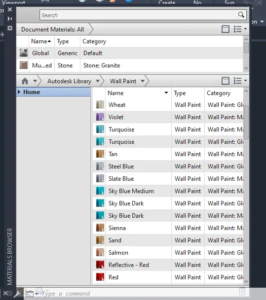
- Now take the command MAT for assign the property to object
- Take the required property for the object as wall paint for footing and doors
Step10:
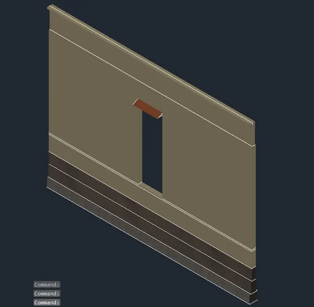
- Select the object and take property left click and take assign to selected objects
- Assing the property for wall footing and lintel as per the required of object
Step11:
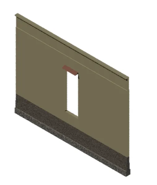
- From the ribbon > visuals > take the Next go to rendering option and rendering
Result: