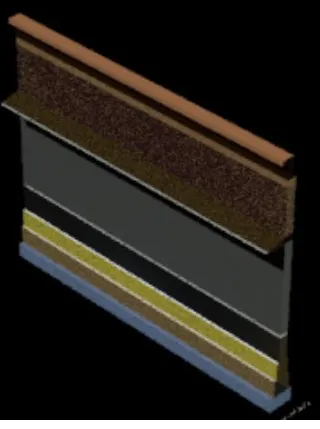
Creating 3D Isometric view of various structural elements in AutoCAD
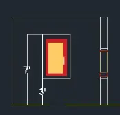
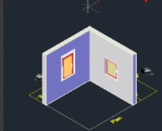
1. Create a 3D Isometric View of the building with plan and elevation given.
AIM:
To Create a 3D isometric view of the building with plan and elevation using Autocad
PROCEDURE:
- open a new AutoCAD file> 3D Modeling
- let's change the units for that on the command prompt type units>engineering>inches>0"-0".
- set the limits, on the command prompt type 'Limax' > 100',100'
- on the command prompt type 'Limits' > 0,0
- By using the line command draw lines of distances 10'-9",3',3'-2" and thickness of 9".
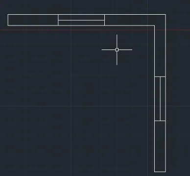
- now go to the southwest isometric view & by using the reg command region of the object
- by using extrude command to extrude the drawn object.
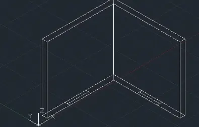
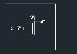
- now, go to the right view and draw the rectangle for the window by using the rec command.
- southwest view, extrude it by 9". and by using a sub command subtract the windows .
 b
b
RESULT:
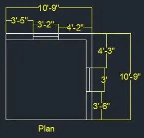
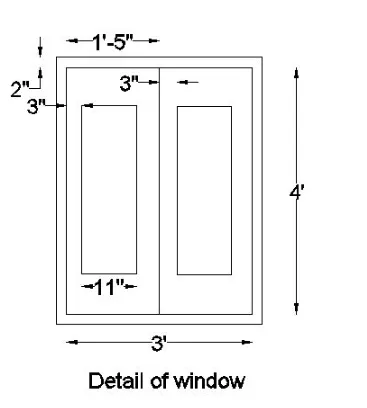
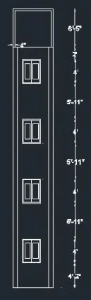
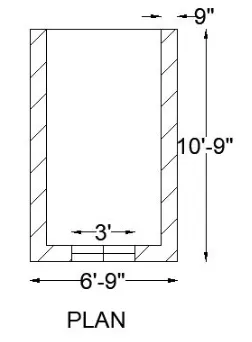
2. Create the 3D View of the Building Façade as given in the plan and elevation. Also, see the detail of the window.
AIM:
To Create the 3D view of the Building facade as given in the plan and elevation.
PROCEDURE:
- open a new AutoCAD file> 3D Modeling
- let's change the units for that on the command prompt type units>engineering>inches>0"-0".
- set the limits, on the command prompt type 'Limax' > 100',100'
- on the command prompt type 'Limits' > 0,0
- by using line command draw the desired line as below.
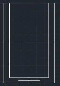
- now, by using MT, DIM, & Hatch commands write the text, give the dimension, and hatch the wall as below.
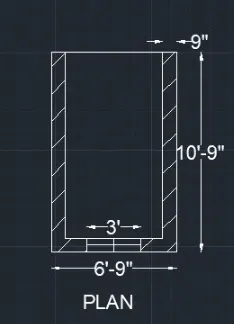
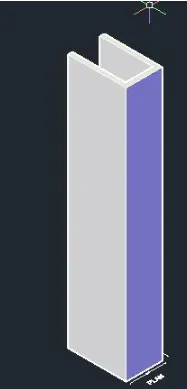
- by using extrude command to extrude the drawn object.
- In the right-side view, draft the window by using lines and rectangle commands.
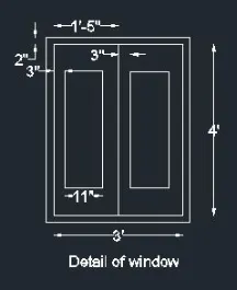
- add the window in the southwest isometric view.
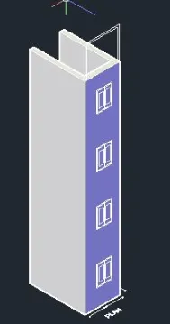
RESULT:
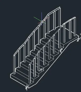
3. Create the isometric 3d view of a stair with a railing as shown in the plan and elevation. Assume the size of the balustrades and the handrails.
AIM:
To create the isometric 3d view of a stair with a railing as shown in the plan and elevation using 3D AutoCAD software.
PROCEDURE:
- open a new AutoCAD file> 3D Modeling
- let's change the units for that on the command prompt type units>engineering>inches>0"-0".
- set the limits, on the command prompt type 'Limax' > 100',100'
- on the command prompt type 'Limits' > 0,0
- by using the line command draw the desired line as below. and create the plan in the top view.
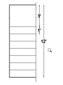
- Go to the front view and create tread and riser with the by using line command.
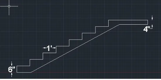
- by using extrude command to extrude the drawn object.
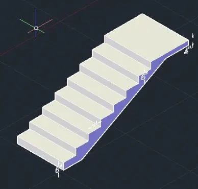
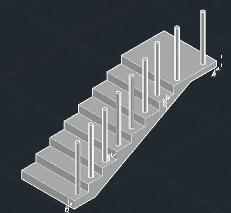
- now. draw the railing, by using a circle (dia 2") and extrude (3'-2") command.
RESULT:
4. Create the 3D view of a Wall with spread footing. Create the Door opening only. Assume the size of the parapet and the coping. See the plans and elevation for the details. Also, create a rendered view of the model with materials as of your choice.
AIM:
To Create the 3D view of a wall with spread footing and to also create a door opening using autocad
PROCEDURE:
- open a new AutoCAD file> 3D Modeling
- let's change the units for that on the command prompt type units>engineering>inches>0"-0".
- set the limits, on the command prompt type 'Limax' > 100',100'
- on the command prompt type 'Limits' > 0,0
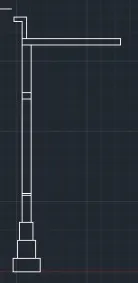
- In the right view create the plan, by using the line command draw the desired line as below.
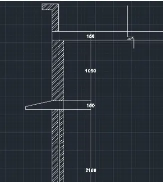
- by using the hatch and dim command to give hatch and dimension.
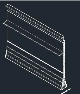
- by using extrude command to extrude the drawn object.
- go to ribbon bar >visualization> material browser > at the material to each element.
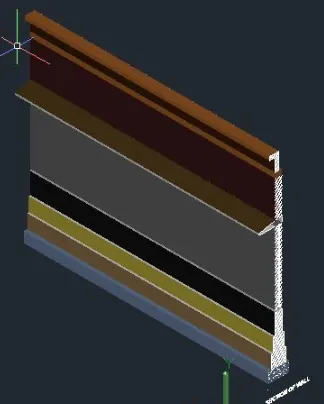
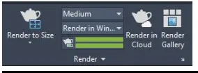
- go to the Ribbon bar > visualization>render to size.
RESULT: