Creating 3D Isometric view of various structural elements in AutoCAD
AIM-1. Create a 3D Isometric View of the building with plan and elevation given.
PROCEDURE-
- First we have to open the autocad and the set the maximum limit and minimum limit on the screen.
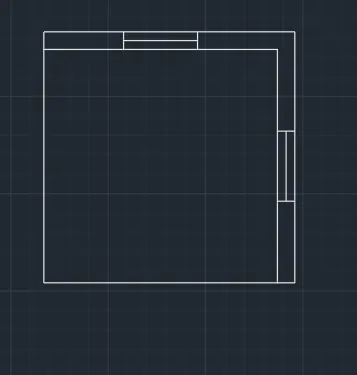
- Here first have to draw the rectangle using the rectangle command, as shown in the figure.
- Next we have to draw the two windows of sizes of 3' x 9" and 9" x 3'-2".
- Now we draw the elevation of A and the elevation of B, as shown in the below figures.
- First we draw the window of the size 3' x 4' as shown in the below figure.
- We draw the this window using the line command and extruded using the extrude command.
- We draw the given elevations using the line command and we put the dimensions using the dimlinear command.
-
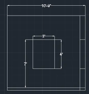
- Next we draw the window of the size 3'-2" x 4' as shown in the below figure.
- We draw the this window using the line command and extruded using the extrude command.
- Next we draw the walls using the extrude command as shown in the figure.
- Next we use the layers for providing the colours to them.
- Next we attach the created windows to the walls shown in the below figure.
RESULT-
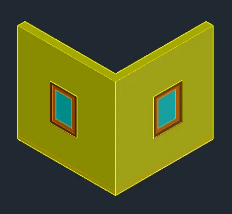
AIM-2. Create the 3D View of the Building Façade as given in the plan and elevation. Also, see the detail of the window.
PROCEDURE-
- First we have to open the autocad and the set the maximum limit and minimum limit on the screen.
- Here first have to draw the rectangle using the rectangle command, as shown in the figure.
- Next we have to draw the window of size of 3'-2" x 9".
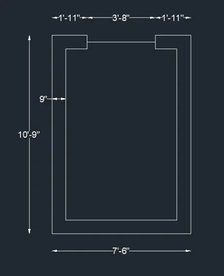
- Next we use the region command and select the objects, then press enter.
- Then after total objects will become the one region.
- Next we need to extrude the plan using the extrude command, with the height of 40'-10".
- Next we need to substract the four window portion vertically in a building facade with the distance 5'-11" with the window size of 3' x 4'.
- Next we use the union command and press enter.
- Then after select the total drawing and press enter.
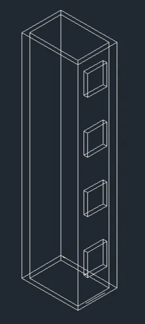
- Next the window portion will be clearly visible in the building facade as shown in the below figure.
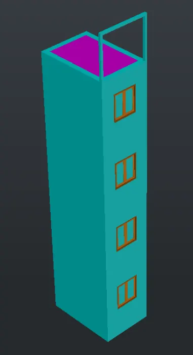
- Next provide the layers for the building facade of skyblue colour, as shown in the below figure.
- Next we close the top surface of the building facade using the extrude command as shown in the below figure.
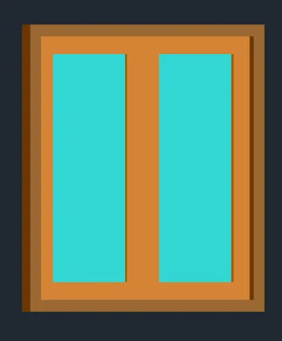
- Next we draw the window of the size 3'-2" x 4' as shown in the below figure.
- We draw the this window using the line command and extruded using the extrude command.
RESULT-
AIM- Create the ismoteric 3d view of a stair with railing as shown in the plan and elevation. Assume the size of the balustrades and the hand rails.
PROCEDURE-
- Draw a rectangle of dimensions 3’X12’
- Explode the rectangle
- Offset the side edges to inside to a distance of 1”
- Offset the bottom edge to upside 12 times to a distance of 1’ as shown in figure
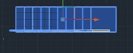
Change the view to 3d by clicking on home button of view cube and chance the view to right view
Set UCS as Right
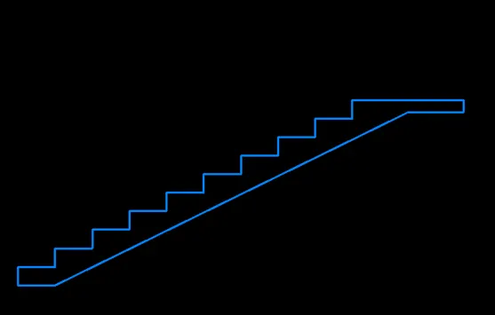
- Start line command and draw a vertical line of length 6”
- Draw a horizontal line of length 1’
- Repeat the same process for 12 times to draw 12 steps
- After reaching 12 steps draw a landing of length of 3’
- Draw a line of 1’ at the bottom step
- Draw a line of 6” at the top right edge of landing
- Draw a line of 1’6” backwards
- Draw a slab joining the lines
- Create a region from the side view of the stairs
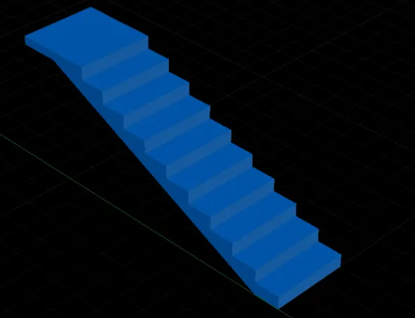
- Extrude the side view to a distacne of 3’ as shown in figure
- Draw circle of diameter 1” with 2” offset from the top right edges of the first thread of staircase
- Change the circle into a region
- Extrude the region to a height of 3’ as shown in the figure
- Draw a handrail stand at the bottom with dimension 2” and extrude
- Draw a polyline connecting all the top edges of hand rails
- Change the UCS to front
- Draw a circle of diameter 2” on top of the first hand rail
- Create a region of the circle drawn
- Start Sweep command
- Select the circle as object to sweep
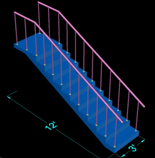
- Select the poly line drawn as path of sweep as shown in figure
- Copy the same to the other side
Result:
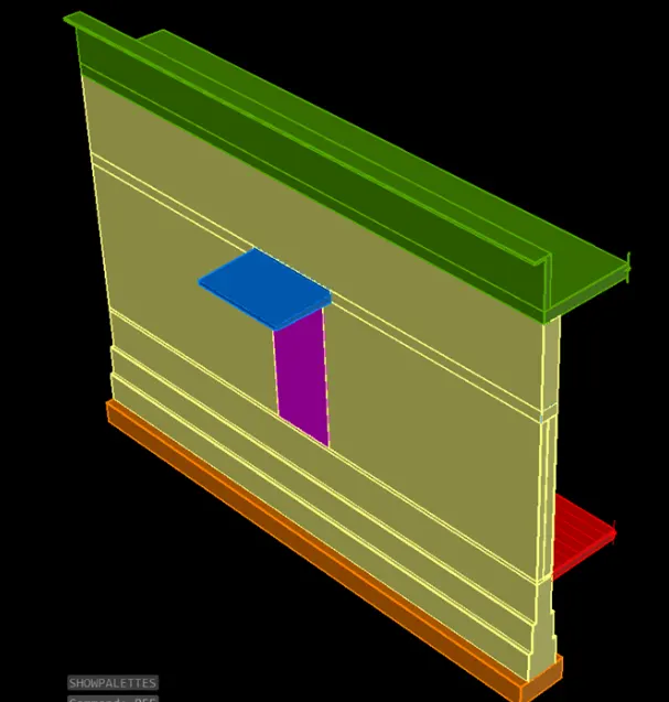
AIM-Create the 3D view of a Wall with spread footing . Create the Door opening only. Assume the size of the parpaet and the coping. See the plans and elevation for the details. Also, create a rendered view of the model with materials as of your choice.
PROCEDURE-
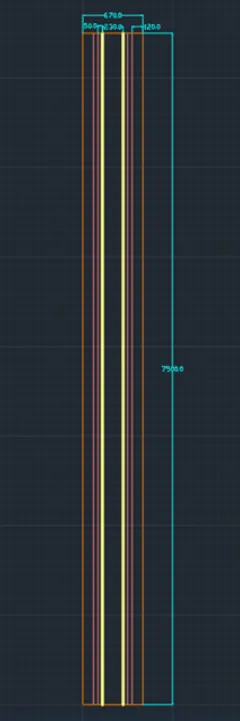
- Draw a rectangle of dimensions 670X7500
- Offset the rectangle to inside to a distance of 120mm
- Offset the offset rectangle inside to distance of 50mm twice.
- Explode all the offset rectangle
- Delete the top and bottom edges of the exploded rectangles
- Extend all the rectangle to top and bottom edges of outer rectangle.
- At the end select the individual lines and change their layers respectively
- Draw a rectabgle of dimenson 50X100mm
- Draw another rectangle with dimensions of 50X50mm
- Draw a line of length 850mm from the edge
- Draw an arc line of the door swing
- Convert the door into block
- Edit the block and add flip parameters
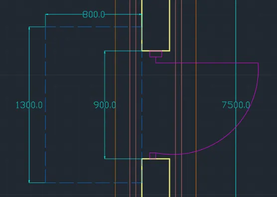
- Create the door opening of 900mm at the middle
- Add the door block by rotating the door
- Draw a line of certal length
- Offset the line to bottom 25mm
- Offset the last offset line bottom to distance of 100mm
- Change the current layer to Wall
- Draw a rectangle of dimension 230X 3300 from the top left edge of Ground level
- Change the current layer to roof level
- Draw roof of thickness 150mm as shown in figure
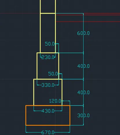
- Draw a Parapet wall of height 600mm as shown in figure
- Draw a rectangle of dimension 230X600, below the floor level as shown in figure
- Draw a rectangle of dimension 330X400, below the first level as shown in figure
- Draw a rectangle of dimension 430X400, below the second level as shown in figure
- Change the current layer to Footing
- Draw a rectangle of dimension 670X300, below the third level as shown in figure
- Draw a line along the length of the door of 230mm at the ground level
- Offset the line to belwo to distanc of 50mm below the ground level
- Offset the line to distance of 2100 to above
Change the current layer to Door Shade
- Draw the door shade as shown
- The created boundaries are to be extruded to a distanc eof 7500mm
- Select the boundaries by changing their respective current layer
- Door opening is added by drawing a rectangle at the door locaton from the plan view
- Then from the extruded part the door region is subtracted from the wall using SUBTRACT command
- Similarly door shade is created with the opening above
- After door shade remaining layer is extrude
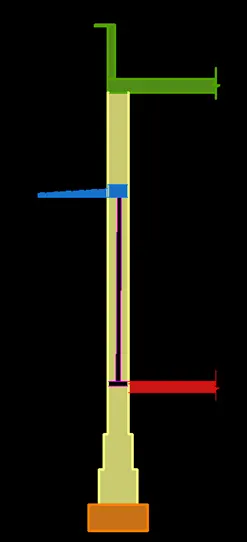
RESULT-