Creating 3D Isometric view of various structural elements in AutoCAD
Aim:
To create 3D isometric view for various structural elements such as a Plan, Staircase, Wall Footing and Building Facade using AutoCAD 3D Tools.
Introduction:
- The Drafting of 3D objects can be done using the 3D Modelling option in AutoCAD software.
- It helps to create and visualise the 3D objects which are created.
- We can also render the image after assigning certain material properties to the objects such as Wall Paint, Furniture etc.,
- The various commands used in Creating the 3D models are:
- Extrude
- Region
- Boundary
- Press and Pull
- Sweep
- Circle
- Rectangle
- UCS
- Copy
- Move
- Dimension Linear
- Pyramid
- Cone
- Revolve
- Solid Edit
- Fillet Edge
- Chamfer
- 3D Mirror
- 3D Align
- Rendering
- Material Library
- Rendening Properties
- Subtract
- Union
Procedure:
1. Isometric View of Building Plan:
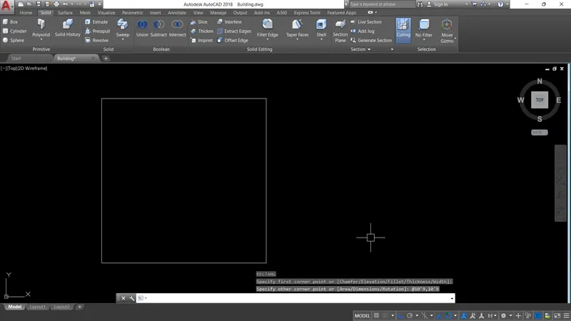
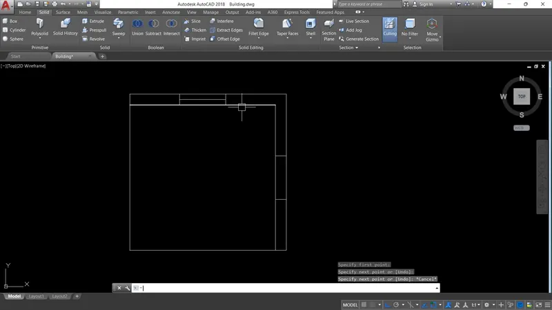
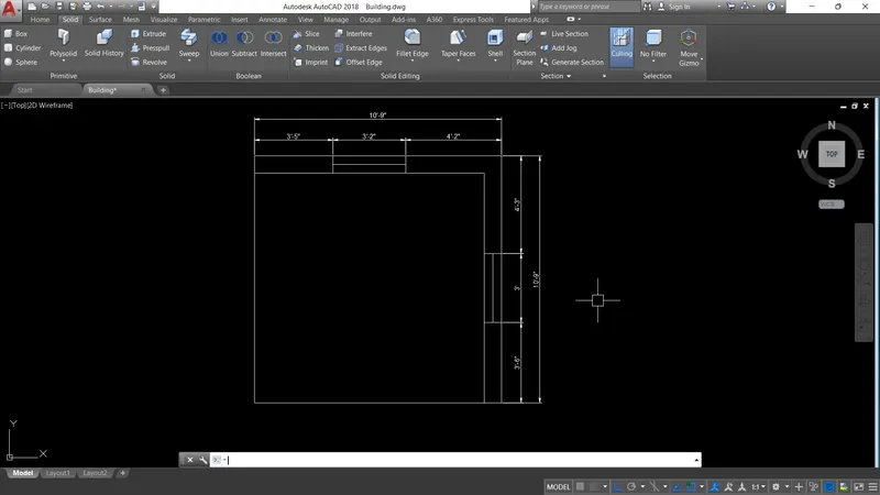
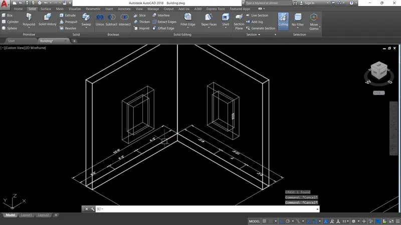
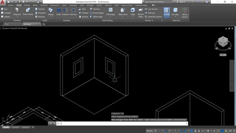
- Firstly develop the plan of the building or room as shown.
- Then using the region or boundary command create a surface.
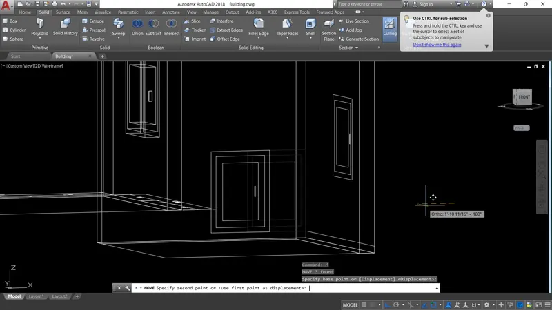
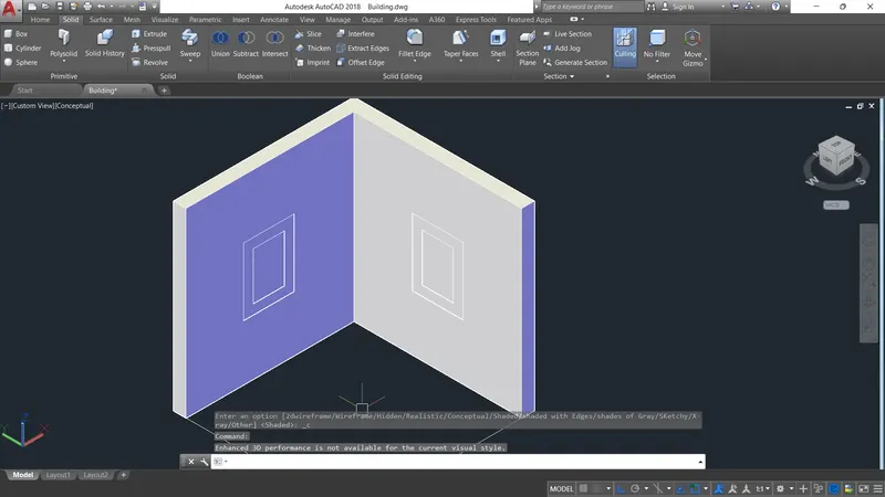
- Using the extrude command extend the surface to the required height.
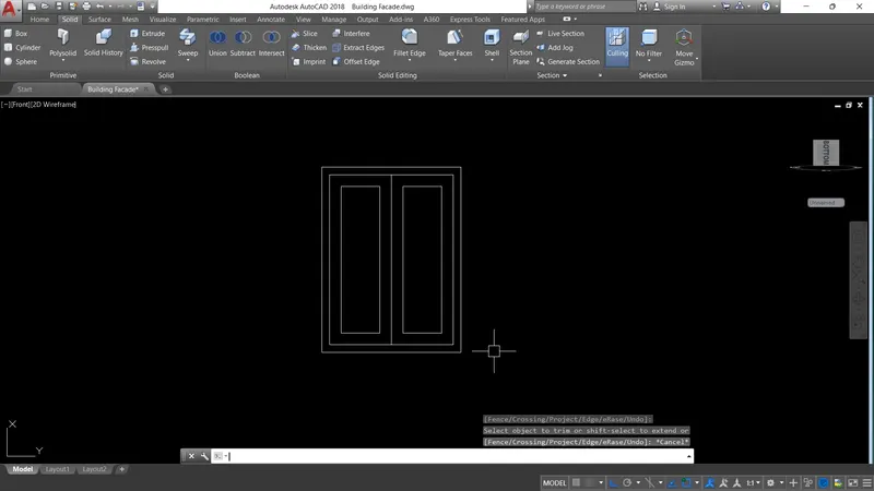
- Create the cross section of window as per the dimensions required.
- Follow the same procedure same as the plan to the window.
- Using the subtract command subtract window portion from the wall layer.
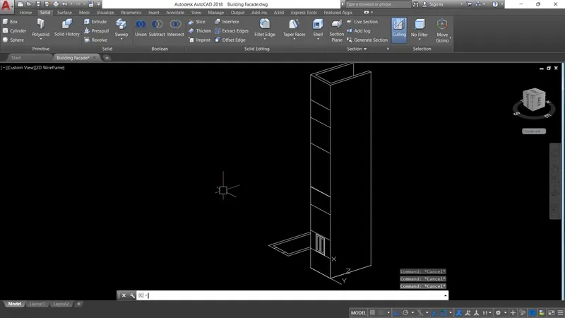
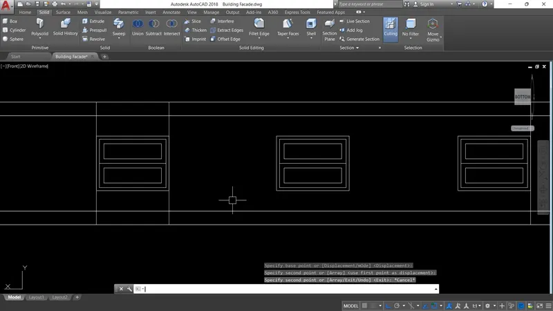
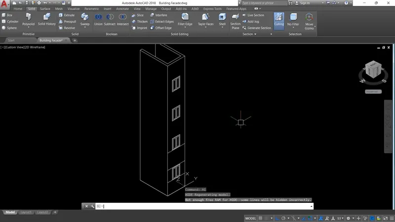
2. Building Facade:
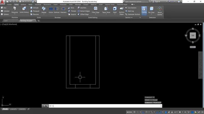
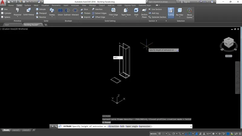
- Create the plan on the XY Plane using the specified dimensions.
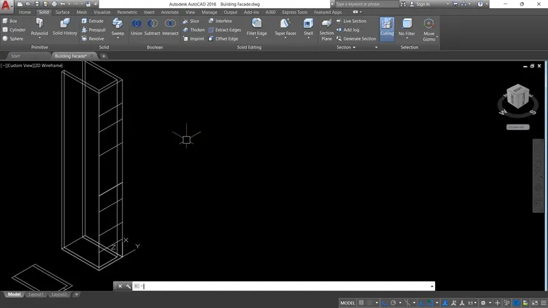
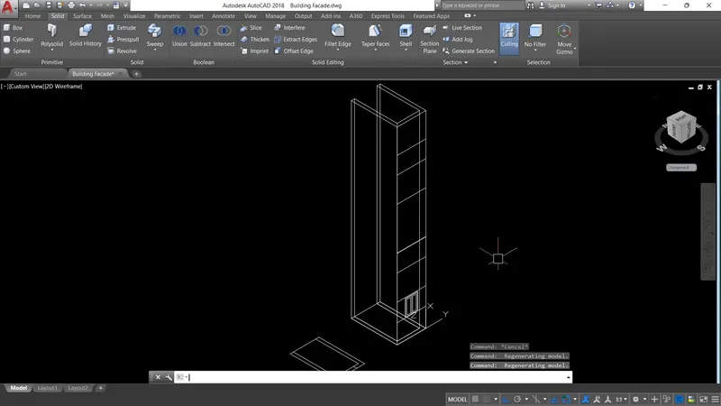
- Create regions for different objects and extrude as per the requirement.
- Now using the subtract and union apply them along the elevation where ever needed.
- We can also give different colours to the different layers present in the Drawing.
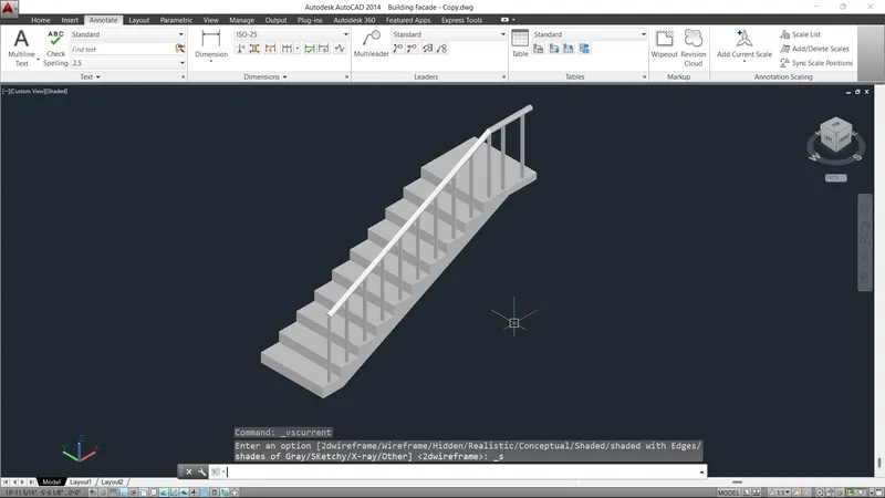
3. Staircase:
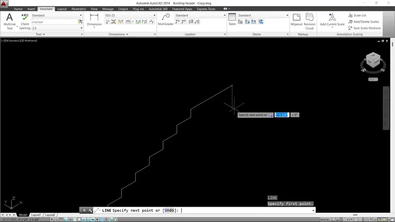
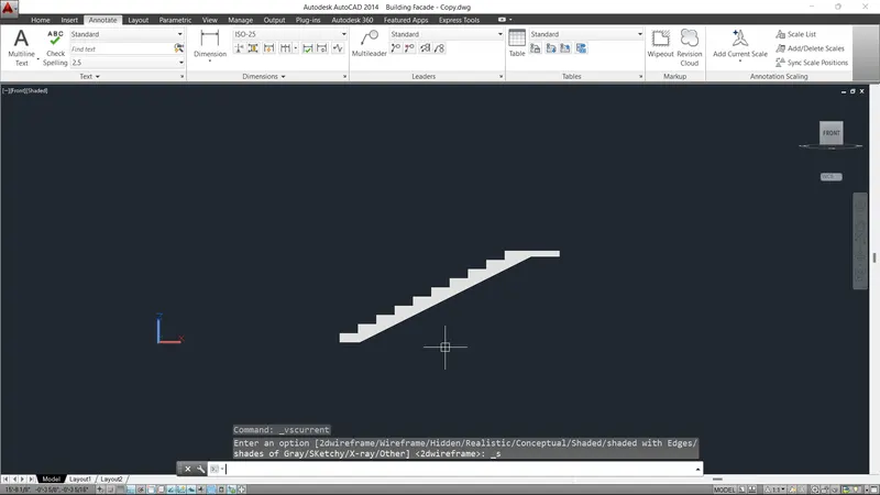
- Firstly create the section of the Staircase on the YZ Plane using the UCS command.
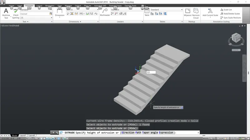
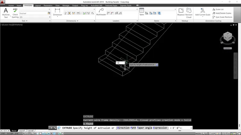
- Now create a region and use the extrude command to stretch the object as per required distance.
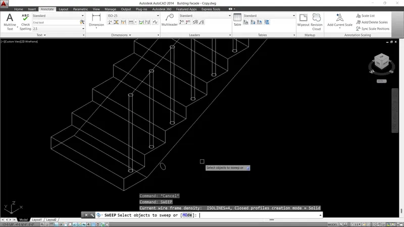
- Now to create the Railing and Balustrade use the help of Sweep and Polyline option.
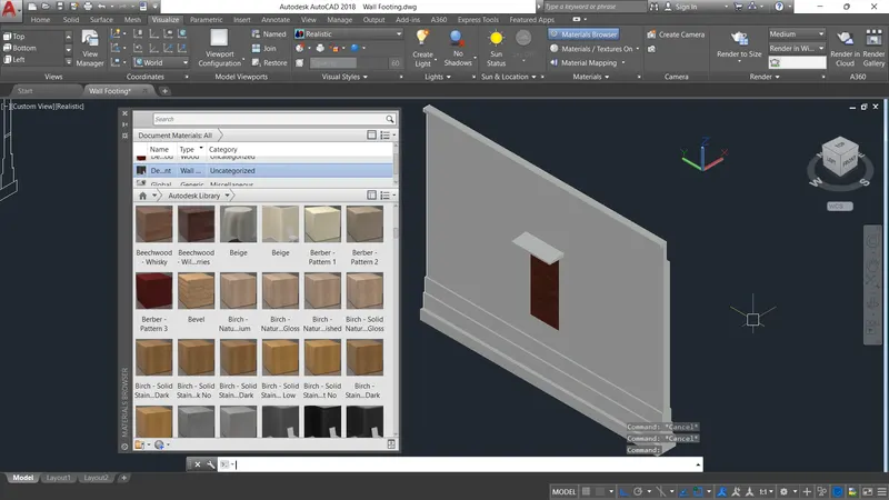
4. Wall Footing:
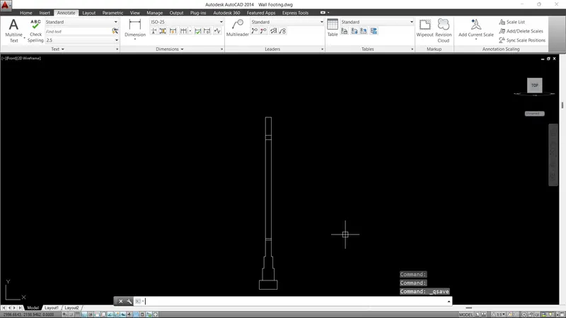
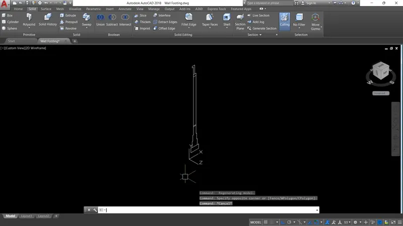
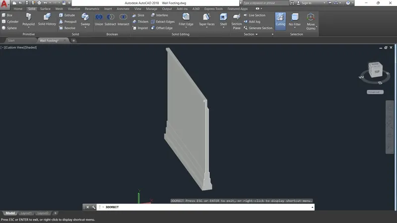
- Create the section of the Wall Footing on the YZ Plane with help of UCS option.
- Create a region for the Section with the help of region or boundary command.
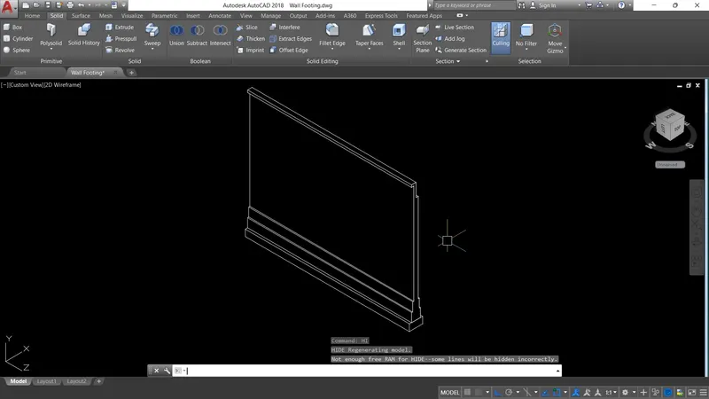
- With the help of Extrude command extend the section for the required length.
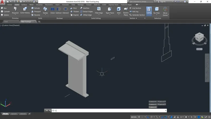
- Now create anoher solid with the dimension of door and sunshade.
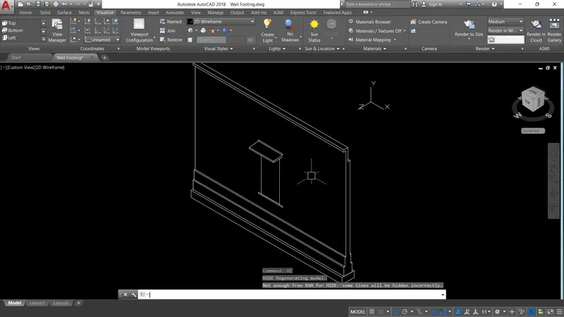
- Using the Subtract command subtract the area of door from the solid wall footing.
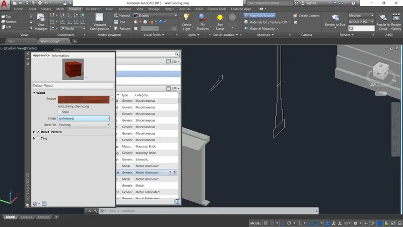
- Now from the Material properties option assign properties to the wall such as Wood with some finishing.
- Wall Painting can also be provided to the wall and different colours to the Footings as well.
- After assigning material properties now we can render the image of the object.
- Using the render command and render properties manager we can select the quality of render and types of render we need to require for the solid object.
- Save the rendered image of required file type such as PNG or JPG etc.,
Result:
We have created 3D isometric view for various structural elements such as a Plan, Staircase, Wall Footing and Building Facade along with rendering using AutoCAD 3D Tools.
The respective drawing and Rendered images are attached