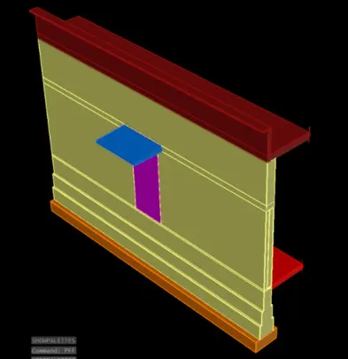
Creating 3D Isometric view of various structural elements in AutoCAD
AIM - Creating 3D Isometric view of various structural elements in AutoCAD.
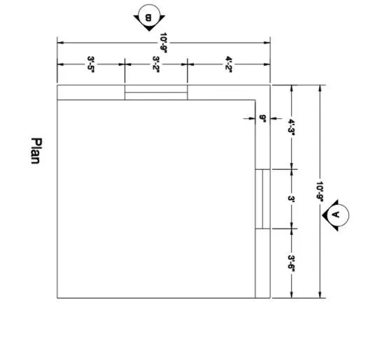
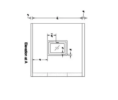
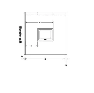
1. Create a 3D Isometric View of the building with plan and elevation given.
 |
 |
Procedure -
Under Drawing Units, select Archetectural (feet and inches)
Now the lower limit is set to 0', 0' and upper limit to 50', 50'
Type Z enter to zoom and A enter to all.
Now in settings selecting 3D Modelling and visual style control to 2D wireframe.
A default layer for both dimension, windows,text and lines was choosen with a colour
Using the line command the Plan, Elevation A and Elevation B was drawn.
The walls and windows was placed in two respective layers.
Using the DIMLIM command the dimensioning was completed.
Using the single line text all the required texts was also made.
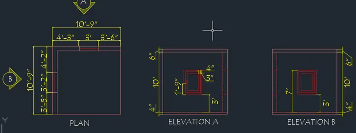
A copy of plan layout is taken to draw the 3D image.
All the layers exept the wall and window layer was turned off.
The south west ismetric view is made the default view.
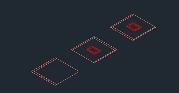
Type BO to open the boundary command
Dialogue box will open
Click on > Pick a point
Click on the internal portion of wall and press
Enter
Click on the extrude option from from the home tab.
Select object > Click on the walls
Specify extrude height > 10'10" and press
Enter
Change the visual style control > Shaded
It will shows the following result
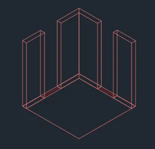
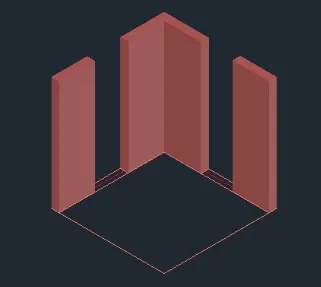
The next task is to project the windows for that:
Type REC and draw a rectangle on top of the window.
Click on the extrude option from from the home tab.
Select object > Click on the rectangle
Specify extrude height > 3' and press
Enter.
Use the Extrude, Substract and union command to finish and place the window.
In the similar way the other window was also created.
Change the visual style control > Shaded
It will shows the following result

Creating Elevation Windows.
Change the current layer to Window Frame.
Type UCS and click on face and select the face having 3' wide window
Draw a rectangle of dimension 3',4'
Offset the rectangle to inside to distnce of 3"
Offset the inside rectangle to inside at a distnce of 4"
Start the boundary command and click on pick points
Click inside the window frame area and press enter
Type SUBTRACT command
Select the bigger region and then select the smaller regions to subtarct them.
Follow the same procedure for all the three boxes.
In the same manner window mullion layer and window glass layer was made
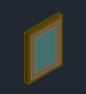
Now using the MOVE command place the window at the correct position as shown.
The floor area was also made into a region and a suitable colur color was provided to it.
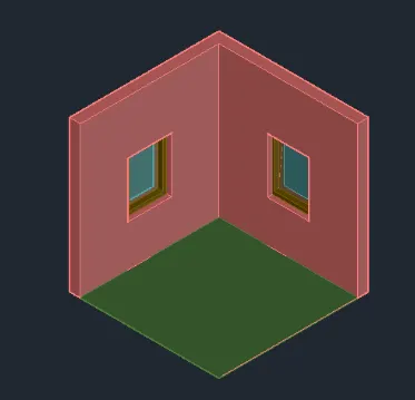
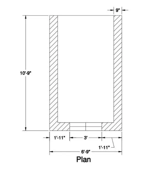
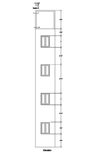
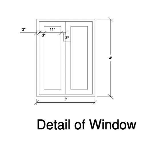
2. Create the 3D View of the Building Façade as given in the plan and elevation. Also, see the detail of the window.
 |
 |
Procedure -
Under Drawing Units, select Archetectural (feet and inches)
Now the lower limit is set to 0', 0' and upper limit to 50', 50'
Type Z enter to zoom and A enter to all.
Now in settings selecting 3D Modelling and visual style control to 2D wireframe.
A default layer for both dimension, windows,text and lines was choosen with a colour.
Using the line command the Plan, Elevation A and Elevation B was drawn.
The walls and windows was placed in two respective layers.
Hatching with pattern was used to represent the walls.
Using the DIMLIM command the dimensioning was completed.
Using the single line text all the required texts was also made.
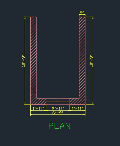
A copy of plan layout is taken to draw the 3D image.
All the layers exept the wall and window layer was turned off.
The south west ismetric view is made the default view.
Type BO to open the boundary command
Dialogue box will open
Click on > Pick a point
Click on the internal portion of wall and press
Enter
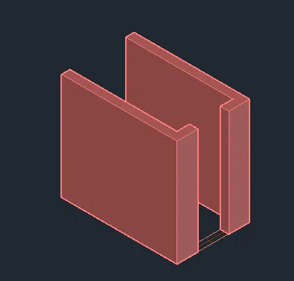
Click on the extrude option from from the home tab.
Select object > Click on the walls
Specify extrude height > 9'11" and press
Enter
Change the visual style control > Shaded
It will shows the following result
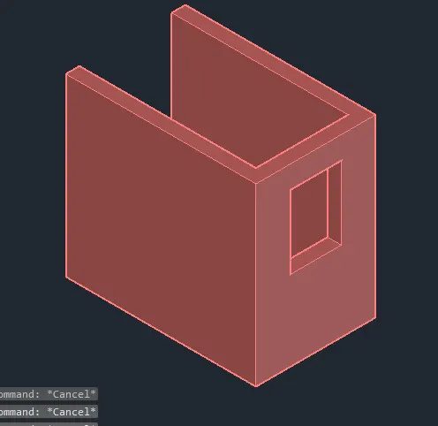
The next task is to project the windows for that:
Type REC and draw a rectangle on top of the window.
Click on the extrude option from from the home tab.
Select object > Click on the rectangle
Specify extrude height > 3' and press
Enter.
Use the Extrude, Substract and union command to finish and place the window.
In the similar way the other window was also created.
Change the visual style control > Shaded
It will shows the following result
Creating Elevation Windows.
Change the current layer to Window Frame.
Type UCS and click on face and select the face having 3' wide window
Draw a rectangle of dimension 3',4'
Offset the rectangle to inside to distnce of 2"
Offset the inside rectangle to inside at a distnce of 3"
Start the boundary command and click on pick points
Click inside the window frame area and press enter
Type SUBTRACT command
Select the bigger region and then select the smaller regions to subtarct them.
Follow the same procedure for all the three boxes.
In the same manner window mullion layer and window glass layer was made
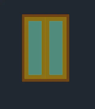
Now using the MOVE command place the window at the correct position as shown.
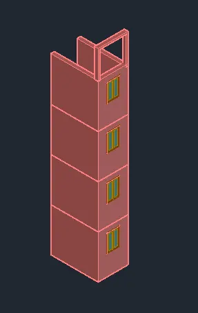
The building is made of four floors ans each floor layout is same.
So the ground floor is copied and stacked on top of each other as shown
The upper part of building was then drawn using line command, converted into region using the boundary command and finally extrude command was used to extent it
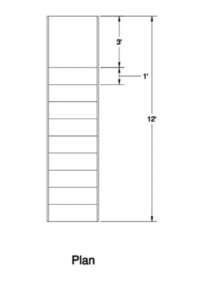
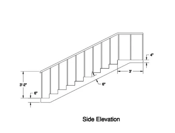
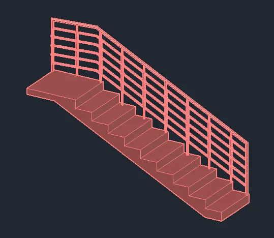
3. Create the ismoteric 3d view of a stair with railing as shown in the plan and elevation. Assume the size of the balustrades and the hand rails.
 |
 |
Procedure -
Under Drawing Units, select Archetectural (feet and inches)
Now the lower limit is set to 0', 0' and upper limit to 50', 50'
Type Z enter to zoom and A enter to all.
Now in settings selecting 3D Modelling and visual style control to 2D wireframe.
A default layer for both dimension, windows,text and lines was choosen with a colour.
Using the line command the Plan and side Elevation was drawn.
The walls and handrails was placed in two respective layers.
Using the DIMLIM command the dimensioning was completed.
Using the single line text all the required texts was also made
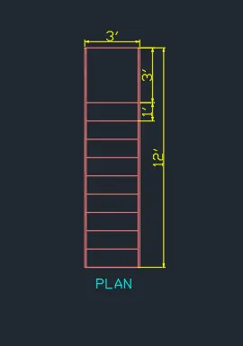
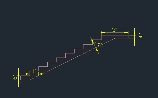
A copy of plan layout is taken to draw the 3D image.
All the layers exept the wall layer was turned off.
The south west ismetric view is made the default view.
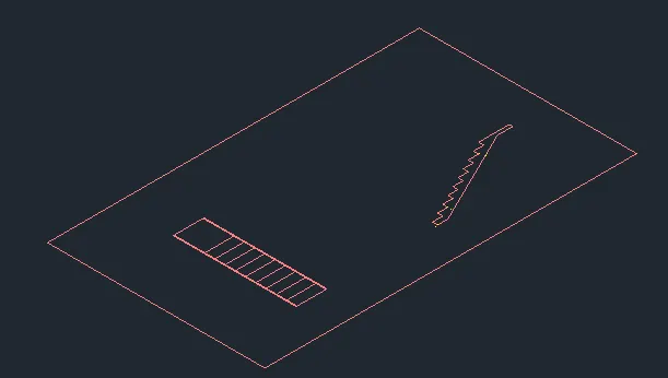
Type BO to open the boundary command
Dialogue box will open
Click on > Pick a point
Click on the internal portion of steps and press Enter
Click on the extrude option from from the home tab.
Select object > Click on the walls
Specify extrude height > 3' and press
Enter
Change the visual style control > Shaded
It will shows the following result
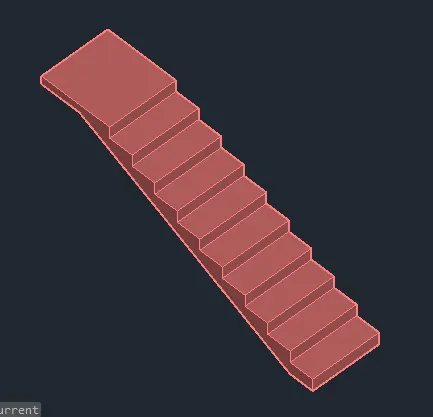
To draw the hand rails.
A circle of radius .75" was drawn.
A circle with same centre and of radious .4" was drawn.
.4" circle is extruded to a height of about 3'-2 and the .75" circle was extruded to a height of 2'
The cylindircal tube of larger dia circle is raised to a height of about 6".
Now a sphere of radius 1" was drawn placed at the centre of the larger dia cylinder.
Using the Union command al of them was made into a single unit ans then it was placed on steps as required.
Draw a polyline connecting all the top edges of hand rails.
Draw a circle of diameter 2" on top of the first hand rail.
Create a region of the circle drawn and do a Sweep command.
Select the circle as object to sweep.
Select the poly line drawn as path of sweep as shown in figure.
Copy the same and place them at equal intervals as required.
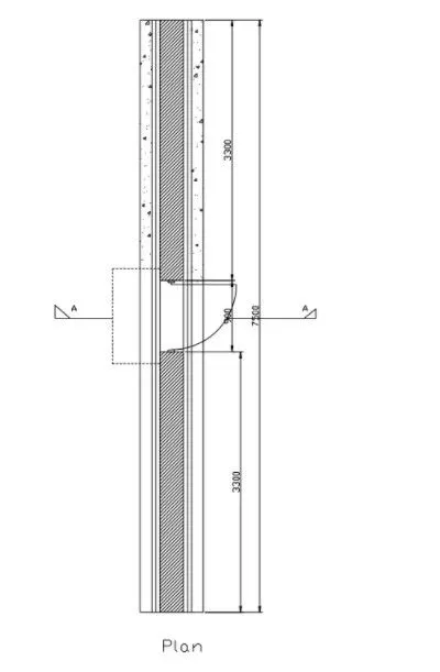
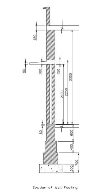
4. Create the 3D view of a Wall with spread footing . Create the Door opening only. Assume the size of the parpaet and the coping. See the plans and elevation for the details. Also, create a rendered view of the model with materials as of your choice.
 |
 |
Procedure -
Under Drawing Units, select metric (millimeter)
Now the lower limit is set to 0, 0 and upper limit to 100, 100
Type Z enter to zoom and A enter to all.
Now in settings selecting 3D Modelling and visual style control to 2D wireframe.
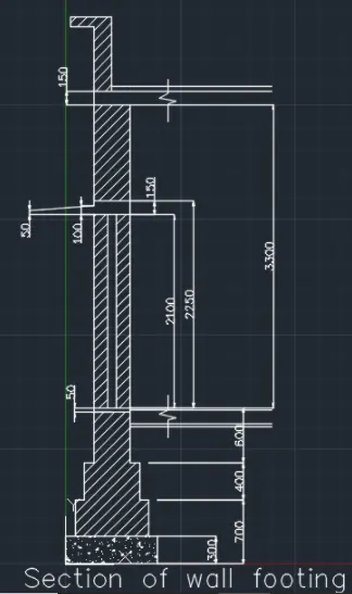
Using the line command the Plan and section was drawn.
All the respective materilas like dimenisons, walls, door etc was placed in the same layer.
Hatch commands of texture and pattern was used for hatching
Using the DIMLIM command the dimensioning was completed.
Using the single line text all the required texts
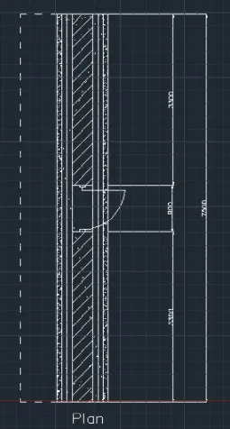
A copy of plan layout is taken to draw the 3D image.
The south west ismetric view is made the default view.
Type BO to open the boundary command
Dialogue box will open
Click on > Pick a point
Click on the internal portion of footings and walls and press Enter
Click on the extrude option from from the home tab.
Select object > Click on the walls and footings
Specify extrude height > 7500 and press
Enter
The rectangle command, extrude command and subtract command was used to provide opening for wall.
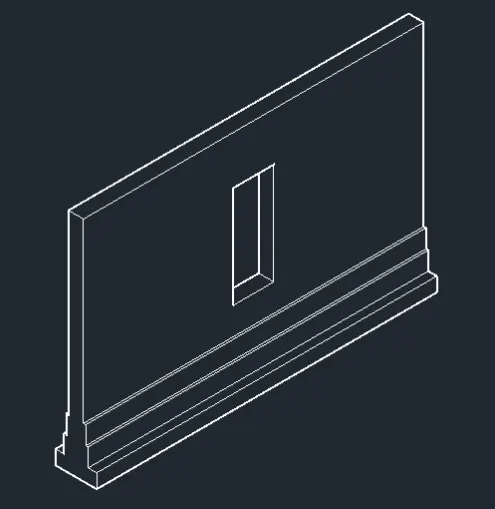
The layers was applied with different colors respectively for individual parts like sun shade, doors,footing and parapet etc.