Creating 3D Isometric view of various structural elements in AutoCAD
AIM : Creating 3D Isometric view of various structural elements in AutoCAD.
Introduction: In this challenge i have draft the above meationed drawing i.e, Creating 3D Isometric view of various structural elements in AutoCAD. here in this challange i have attached all the drawings in a image format and with the proper procedure as possible.
The process of creating a mathematical representation of any surface of an object in three dimensions by using special software is called 3D modeling. A 3D model can even be represented as a two-dimensional image by using the 3D rendering process. The user can also create 3D models physically using 3D printers. There is a lot of software that is used to create 3D models like AutoCAD, MAX, MAYA, and many more.
3D models are high in demand with the game developers as well. Some computer games use already rendered images of 3D models, which are known as sprites. This helps the designer to view the model in all directions, and they can make sure that the object created is like the original one.
The comman commands which are used in this challange are discussed below,
Selecting of Tools:
- Line: Ribbon< Home< Line, Command: Line or L, Home< Draw< Line.
- Polyline: Ribbon< Home< Polyine, Command: polyline or pl, Home< Draw< polyline.
- Rectangle: Ribbon< Home< rectangle, Command: rectangle or rec, Home< Draw< rectangle.
- Ploygon: Ribbon< Home< Ploygon, Command: Ploygon or pol, Home< Draw< Ploygon.
- Circle: Ribbon< Home< Circle, Command: Circle or C, Home< Draw< Circle.
- Fillet: Ribbon< Home< Fillet, Command: Fillet or F, Home< modify< Fillet.
- Chamfer: Ribbon< Home< Chamfer, Command: Chamfer or cha, Home< modify<Chamfer.
- Move: Ribbon< Home< move, Command: move or M, Home< modify<Move.
- Copy: Ribbon< Home< Copy, Command: Copy or co, Home< modify<Copy.
- TRIM: Ribbon< Home< trim, Command: TRIM or TR, Home< modify
- 3d Fillet: Ribbon< Home< Fillet, Command: Fillet or F, Home< modify< 3d Fillet.
- 3d Chamfer: Ribbon< Home< Chamfer, Command: Chamfer or 3d cha, Home< modify<3d Chamfer.
- 3d Rotate: Ribbon< Home< Rotate, Command: Rotate or 3ro, Home< modify<3d Rotate.
- Extrude: Location: Draw > Modeling > Extrude.
- Sweep: Location: Draw > Modeling > Sweep.
- Union: Location: Modify > Solids Editing > Union.
- Subtract: Location: Modify > Solids Editing > Subtract.
- Intersect: Location: Modify > Solid Editing > Intersect.
Question 1:
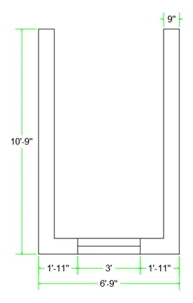
Create a 3D Isometric View of the building with plan and elevation given.
ANS: Here i have attached the image which i have made in autocad 2019,
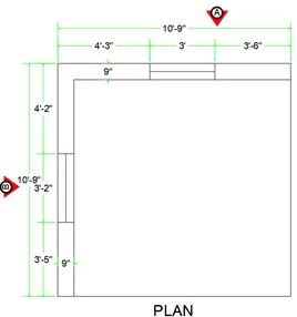
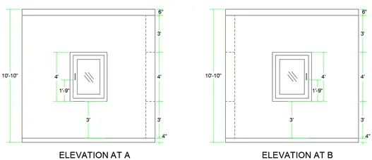
Procedure:
- Open autocad 2019 and select a new file and saved as challange 5 and saved in the skill-lync folder.
- Set the unit of drawing by giving command un in command and selected Engineering with precion 0'-0.0".
- Select limit by giving command limmax and giving the limit 20',20' and entre.
- Adjust the dimension size by giving command d and selecting the same unit as mentioned that is Engineering.
- Select Rec command and draw a rec of size 10'9" x 10'9" as shown in fig.
- select a line command and draw the line in mid of those line and use offset of 1'6" both sides.
- in order to create a window, and again use offset of 9" and offset internally.
- Copy the same by side by side by using co command.
- now select a rec coomand and draw a rec of size 3'x4' as shown in figure.
- use offset of 2" internally to create grove in window.
- and further 2" offset internally to create a panel and to seperate glass panel.
- similarlly copy the same window in the opposite direction as shown in figure.
- use Mtext command ans start writing and write Plan, elevation and etc.
- Now use dimlinear command and provide dimension at proper places.
- and also use dimcontinue in order to provide continue dimension usually easily.
Procedure for creating 3d model:
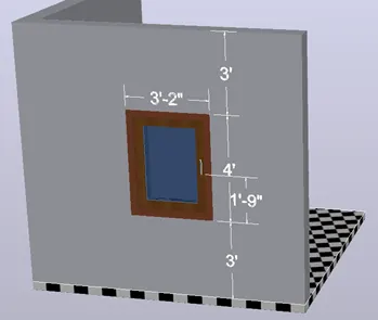
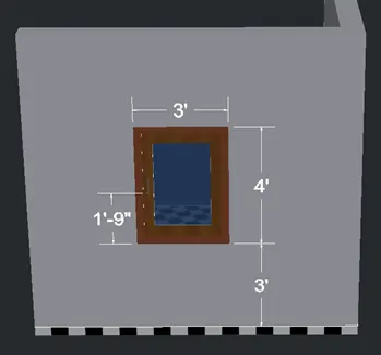
Elevation At A Elevation At B
- Open the Workspaces drop-down list on the Quick Access toolbar, or click the Workspace Switching button on the status bar and then choose 3D Modeling.
- Toolbars, palettes, and Ribbon panels flash on and off, and soon AutoCAD settles down to display the Ribbon, as configured for the 3D Modeling workspace with a few additional panels.
- Click the Application button and choose New; then click Drawing.The Select Template dialog box appears.Choose dwtif you’re working in imperial units or acadiso3d.
- Dwg if you’re working in metric. Click Open. A 3D modeling space appears where, rather than look straight down at the drawing area, you look at it at an angle from above.
- Use the plan and use presspull command and give a height of 10'10".
- Furter above the window and use press pull command again and give a height of 3'
- Now for the window copy the window which is already created and give a prespull command.
- give a height of 2" and internally 1" and for glass panel with height of 0.5" respectivelly.
- Now place the window in the position and now use union option.
- Use the material command and give matrials to window and wall as shown in figure.
- now for providing the dimension on the wall.
- select command ucs and select face option and set on the face.
- Now just simply use dimlinear and provide dimension where ever required.
- This is how a drawing or elevation is created in 3d.
Question 2:
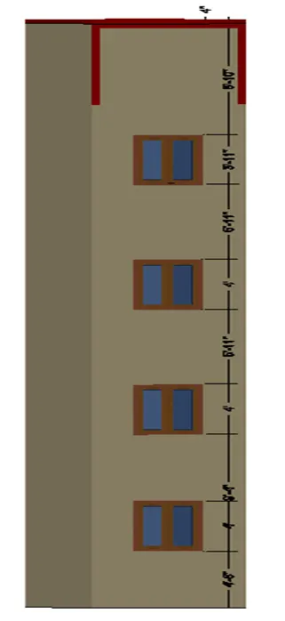
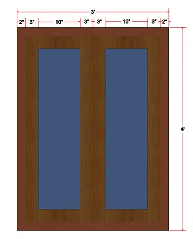
Create the 3D View of the Building Façade as given in the plan and elevation. Also, see the detail of the window.
ANS: Here i have attached the image which i have made in autocad 2019,
Procedure:
- Open autocad 2019 and select a new file and saved as challange 5 and saved in the skill-lync folder.
- Set the unit of drawing by giving command un in command and selected Engineering with precion 0'-0.0".
- Select limit by giving command limmax and giving the limit 20',20' and entre.
- Adjust the dimension size by giving command d and selecting the same unit as mentioned that is Engineering.
- Select Rec command and draw a rec of size 10'9" x 10'9" as shown in fig.
- select a line command and draw the line in mid of those line and use offset of 1'6" both sides.
- in order to create a window, and again use offset of 9" and offset internally.
- Copy the same by side by side by using co command.
- now select a rec coomand and draw a rec of size 3'x4' as shown in figure.
- use offset of 2" internally to create grove in window.
- and further 2" offset internally to create a panel and to seperate glass panel.
- similarlly copy the same window in the opposite direction as shown in figure.
- use Mtext command ans start writing and write Plan, elevation and etc.
- Now use dimlinear command and provide dimension at proper places.
- and also use dimcontinue in order to provide continue dimension usually easily.
Procedure for creating 3d model:
Section at A
- Open the Workspaces drop-down list on the Quick Access toolbar, or click the Workspace Switching button on the status bar and then choose 3D Modeling.Toolbars,
- palettes, and Ribbon panels flash on and off, and soon AutoCAD settles down to display the Ribbon, as configured for the 3D Modeling workspace with a few additional panels.
- Click the Application button and choose New; then click Drawing.The Select Template dialog box appears.Choose dwtif you’re working in imperial units or acadiso3d.
- Dwg if you’re working in metric. Click Open. A 3D modeling space appears where, rather than look straight down at the drawing area, you look at it at an angle from above.
- Use the plan and use presspull command and give a height of 10'10".
- Furter above the window and use press pull command again and give a height of 3'
- Now for the window copy the window which is already created and give a prespull command.
- give a height of 2" and internally 1" and for glass panel with height of 0.5" respectivelly.
- Now place the window in the position and now use union option.
- Use the material command and give matrials to window and wall as shown in figure.
- now for providing the dimension on the wall.
- select command ucs and select face option and set on the face.
- Now just simply use dimlinear and provide dimension where ever required.
- This is how a drawing or elevation is created in 3d.
Question 3:
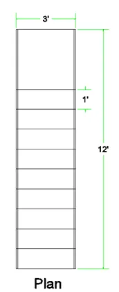
Create the ismoteric 3d view of a stair with railing as shown in the plan and elevation. Assume the size of the balustrades and the hand rails.
ANS: Here i have attached the image which i have made in autocad 2019,
Procedure:
- select a line command and draw the line in mid of those line and use offset of 1'6" both sides.
- in order to create a window, and again use offset of 9" and offset internally.
- Copy the same by side by side by using co command.
- now select a rec coomand and draw a rec of size 3'x4' as shown in figure.
- use offset of 2" internally to create grove in window.
- and further 2" offset internally to create a panel and to seperate glass panel.
- similarlly copy the same window in the opposite direction as shown in figure.
- use Mtext command ans start writing and write Plan, elevation and etc.
- Now use dimlinear command and provide dimension at proper places.
- and also use dimcontinue in order to provide continue dimension usually easily.
Procedure for creating 3d model:

- Open the Workspaces drop-down list on the Quick Access toolbar, or click the Workspace Switching button on the status bar and then choose 3D Modeling.
- Toolbars, palettes, and Ribbon panels flash on and off, and soon AutoCAD settles down to display the Ribbon, as configured for the 3D Modeling workspace with a few additional panels.
- Click the Application button and choose New; then click Drawing.The Select Template dialog box appears.Choose dwtif you’re working in imperial units or acadiso3d.
- Dwg if you’re working in metric. Click Open. A 3D modeling space appears where, rather than look straight down at the drawing area, you look at it at an angle from above.
- Use the plan and use presspull command and give a height of 10'10".
- Furter above the window and use press pull command again and give a height of 3'
- Now for the window copy the window which is already created and give a prespull command.
- give a height of 2" and internally 1" and for glass panel with height of 0.5" respectivelly.
- Now place the window in the position and now use union option.
- Use the material command and give matrials to window and wall as shown in figure.
- now for providing the dimension on the wall.
- select command ucs and select face option and set on the face.
- Now just simply use dimlinear and provide dimension where ever required.
- This is how a drawing or elevation is created in 3d.
Question 4:
Create the 3D view of a Wall with spread footing . Create the Door opening only. Assume the size of the parpaet and the coping. See the plans and elevation for the details. Also, create a rendered view of the model with materials as of your choice.
ANS: Here i have attached the image which i have made in autocad 2019,
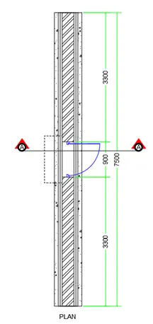
Procedure:
- select a line command and draw the line in mid of those line and use offset of 1'6" both sides.
- in order to create a window, and again use offset of 9" and offset internally.
- Copy the same by side by side by using co command.
- now select a rec coomand and draw a rec of size 3'x4' as shown in figure.
- use offset of 2" internally to create grove in window.
- and further 2" offset internally to create a panel and to seperate glass panel.
- similarlly copy the same window in the opposite direction as shown in figure.
- use Mtext command ans start writing and write Plan, elevation and etc.
- Now use dimlinear command and provide dimension at proper places.
Procedure for creating 3d model:
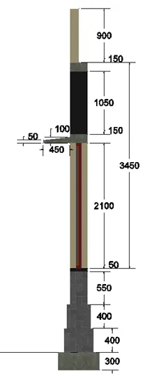
SECTION AT A
- Open the Workspaces drop-down list on the Quick Access toolbar, or click the Workspace Switching button on the status bar and then choose
- settles down to display the Ribbon, as configured for the 3D Modeling workspace with a few additional panels.
- Click the Application button and choose New; then click Drawing.The Select Template dialog box appears.Choose dwtif you’re working in imperial
- units or acadiso3d.
- Dwg if you’re working in metric. Click Open. A 3D modeling space appears where, rather than look straight down at the drawing area, you look at it at an angle from above.
- Use the plan and use presspull command and give a height of 10'10".
- Furter above the window and use press pull command again and give a height of 3'
- Now for the window copy the window which is already created and give a prespull command.
- give a height of 2" and internally 1" and for glass panel with height of 0.5" respectivelly.
- Now place the window in the position and now use union option.
- Use the material command and give matrials to window and wall as shown in figure.
- now for providing the dimension on the wall.
- select command ucs and select face option and set on the face.
- Now just simply use dimlinear and provide dimension where ever required.
- This is how a drawing or elevation is created in 3d.
Result:
- The above shown diagram is of the plan of differnt structural members in Construction that is wall section, windows section and a complete section of a load bearing wall with proper dimension.
- The plan is drafed in 2d but the elevation and section is drafed in 3d with proper materials used.
---------------------------------------------------------END------------------------------------------------------------------