Creating 3D Isometric view of various structural elements in AutoCAD
AIM: To draw a 3D isometric view of:
Construction according to plan and height
Building facade
Staircase
Spread your legs
COMMANDS USED:
Push out.
Offset.
UCS.
Box.
Union.
Subtract.
Move.
3D orbit.
Border.
Sweep.
Provide.
1).
3D isometric view of the building
AIM: Create a 3D isometric view of a building with a floor plan and view.
PEOCEDURE:
Step 1:
Drawing a plan:
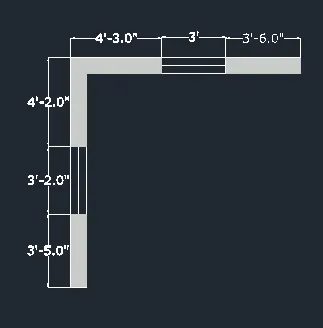
In the top view, use the line command to draw a line 10'9" vertically and horizontally to create L-shaped walls. Offset the line 9" from the two lines.
Step 2:
Draw a window:
Specify an offset of 4'2" from the corner of the wall. Again specify an offset of 3'2" from this line for the window.
Similarly, on the other side, offset 4'3" from the corner, 3' for the window.
Step: 3
Making it 3D:
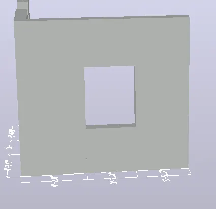
"3do" command for 3D orbit and orbit view so that the 3D view is visible. Now create an area in the wall area with the "BO" command for the border. Go to the shaded view and you will see the border.
Now pull out the area and give it a height of 10'. Command "EXTRUDE", enter height =10'.
Step 4:
To create an opening for the windows:
Draw a rectangle across part of the window. Pull it up to 3' i.e. window sill level.
Similarly, create a rectangle at the top. Pull it down to a height of 3' from the top.
Create a wall layer and place it inside the wall layer.
In the top view, create a plan outline using a curve. Then place it down with the move command "M" @0,0, -10'.
Create an area according to the border. Pull it downwards to a height of 4". Similarly, create a curve at the top and pull it to a height of 6".
Make that connection and place in the wall layer
Step 5:
To create an elevation in 2D:
Altitude A-A
Draw view A from the floor plan in top view. Project the wall line from the plan as well as the window lines.
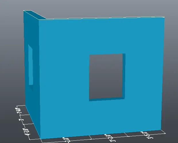
Enter a height of 10', then offset the lines by 3' from the bottom and top to create a window
Then offset 3" for the frame and 4" for the post.
Also offset 4' down for plinth and 6' up for roof plate from 10'.
Create different layers for the frame, post and glass.
Step 6:
Creating a 3D Elevation:
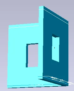
Position the 2D drawing so that it aligns with the 3D .Group height by group command so everything is in a single selection.
Use 3D to rotate the image so that it is parallel to the 3D wall. select an axis and enter an angle of 90 degrees.
Step 7:
Creation of window frame, transom and glass. Use the "bo" command to create an area for the frame.
Take it apart and remove everything except the window. If the region is created entirely, subtract, select a larger region, then a smaller one.
Pull out the area, give it a value of -3".
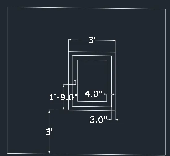
Similarly, create an area for the crossbars with the command "BO" - the border command. Pull it out -1.2".
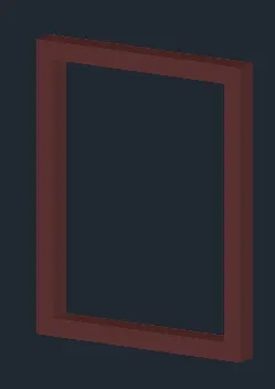
Create an area for the glass by creating a rectangular border if there is no border. Pull it out 0.6".
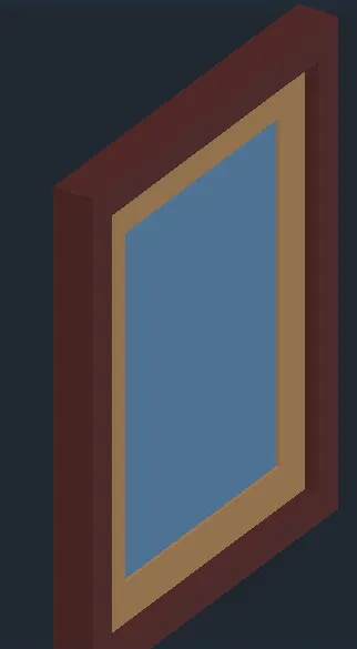
Move the 3D window into the window opening created in the 3D model. Make sure the posts are inside the frame and the glass inside the posts.
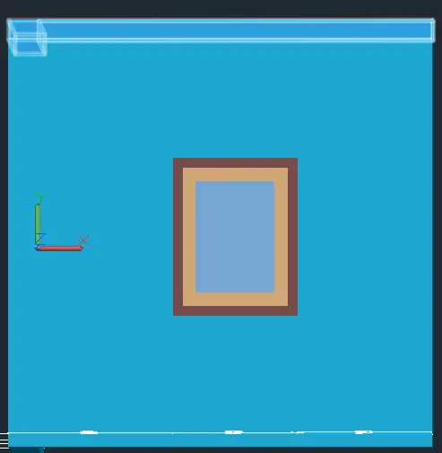
Isometric view of elevation A:
Creating height B:
Switch to the top view and extend the lines from the plan. Draw a 4" offset at the bottom and 6" at the top.
Draw the window at 3" from the bottom and offset 7' from the bottom to get the top of the window. Enter the thickness by moving the rectangle 3" for the frame and 4" for the transom.
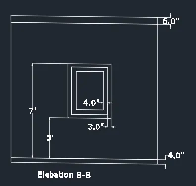
Similarly, create a B-B elevation window the same as we created in A-A elevation.
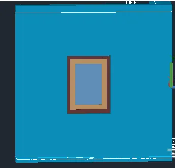
Result:
3D view of a room is drawn
2).
3D view of the building facade
AIM: Create a 3D view of the building's facade
PROCEDURE:
Step 1:
Create a schedule:
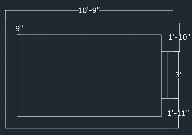
Use the rectangle command to create a rectangle 10'9" by 6'9". Offset 9" for wall thickness. Create a 3' wide window.
Step 2:
Height extension:
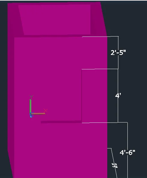
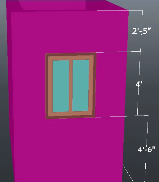
Because the sill height is listed as 4'6" and the window height as 4', and the top height from the window is 2'5".
Total height of one floor =2'5"+4'+4'6" =10'11"
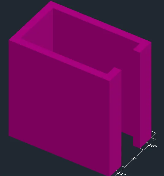
Use the "BO" command to create an extension area in the wall section.
Use the pull command to pull out the 10'-11" high created area.
Step 3:
Creating windows:
Create a rectangle at the bottom of the window position.
Extrude it to a height of 4'6". Similarly, create a rectangle at the top and extrude 2'-5" down.
Use the unite command to connect all the walls.
Step 4:
Draw a 4'X3' rectangle in top view. The window detail is done, 2" offset for the frame and 3" for the jambs, then 12" will be the glass area.
Create an area in the window frame with the "BO" command, making the frame a layer.
-3" offset for frame thickness.
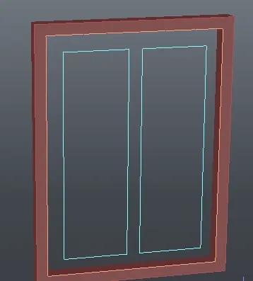
For the posts, create another area on another layer and pull out -1.2".
Also create a region for the glass and pull -0.6".
Move this object and place the window on the gap in the 3D wall.
Step 6:
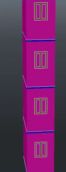
Creating a floor
Switch to top view and create a rectangle. Pull it out 5".
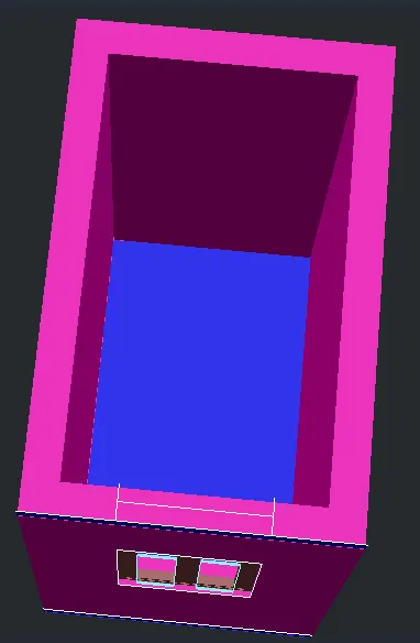
Group the created model and copy the created 1st floor above. Copy the 4 floors as such
Step 7:
Creating the top frame:
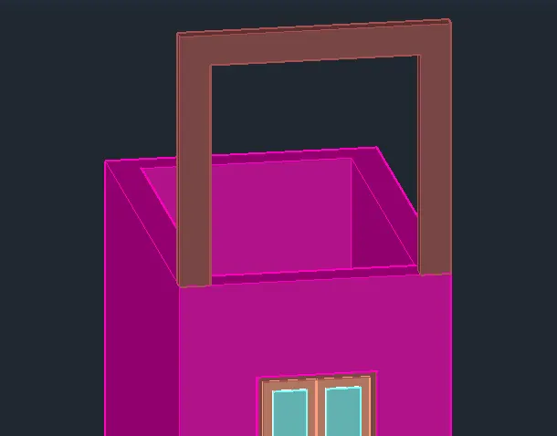
Type "UCS" as a command and place the UCs on top of the building. Draw a 9" x 4" rectangle.
Pull it out 6'5”. Copy it to the other side.
Recreate the rectangle on the top surface. Pull it out -4".
Create the roof at the top with a rectangle and extrusion.
Result:
3).
Creating an isometric 3D view of the staircase
AIM: Create a 3D view of the staircase
PROCEDURE:
Step 1:
Creating steps:
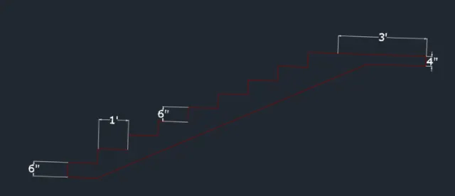
With a tread of 1' and a rise of 6", draw the steps in a top view of the 2D wireframe. The landing is 3' and the waist is 6".
Connect them to form part of the staircase.
Step 2:
Extending the stairs:
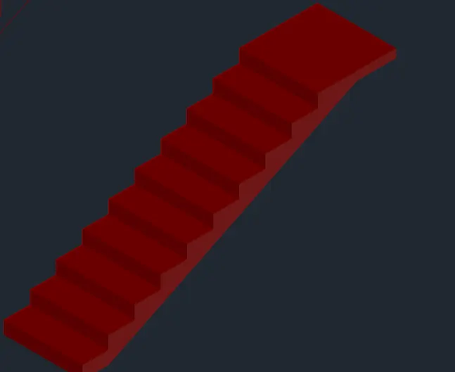
Create an area with the border command. With the 3D orbit, position the slice so that it is visible.
Projecting 3' towards the side as 3' is taken as the width of the staircase. Using 3d rotate -select the x-axis and enter a value of 90 degrees.
Step: 3
Production of balustrades and railings:
Place the UCS on the tread and create a 2" diameter circle. Pull out at a height of 3'2".
Copy it on all steps and also on landing.
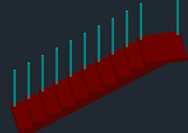
For the railing, create a curve connecting the balustrades using "3dpoly". 3D curve. Create a 2" radius circle and sweep it by selecting the circle and then the curve.
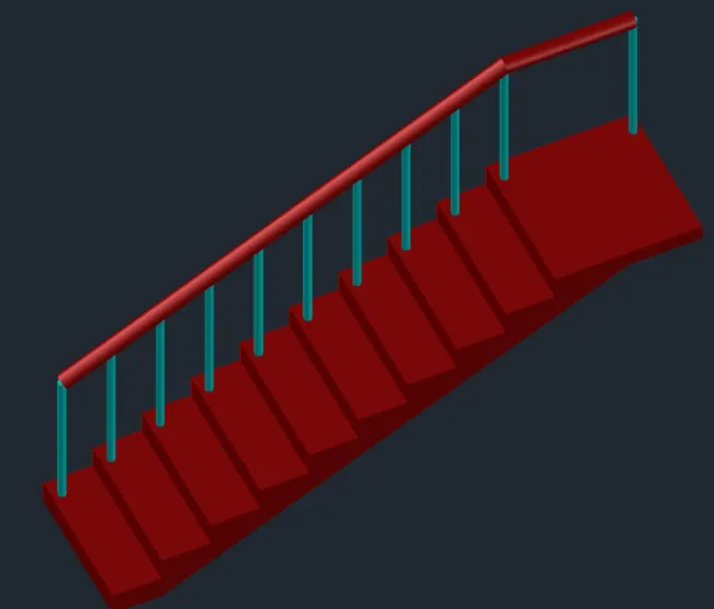
Result:
3D view of stair case is drawn.
4).
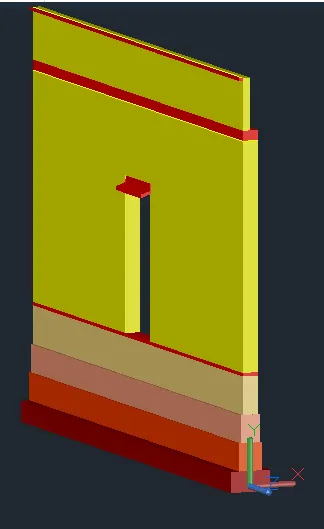
3D view of the wall with the base spread out
AIM: Draw a 3D view of the wall with the base extended
PROCEDURE:
Step 1:
Creating a plan - walls:
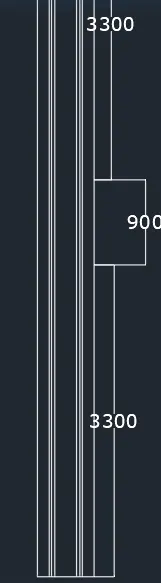
Use the line command to draw a vertical line 7500 mm wide and 230 mm wide
Draw a center line in the wall and offset it by 150mm on either side for a total width of 300mm.
From the 300mm line, offset 25mm on both sides, the total width will then be 350mm.
From the center again offset 300mm on both sides, the total width is 600mm.
Extend the horizontal line. 3300 mm offset on both sides for a 900 mm door opening.
Step 2 :
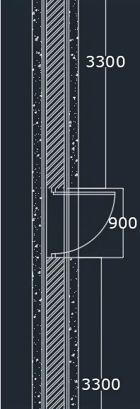
Create a door in the opening with a circle and a line.
Hatch wall, foundation with various hatches.ANS 132 for wall, Solid for foundation, AR-CONC for bottom P.C.C.
Step 3:
Creating a 2D plan on a 3D-base R.C.C
Make a suitable look with 3do. Make layers for treads-R.C.C, treads-stairs, wall and door
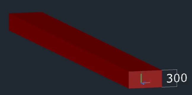
Create a rectangle -profile -R.C.C on the floor plan of the base plate. place on the appropriate layer and copy it. Create an area with the border command.
Pull it out by 300mm
Step 4:
Creating heel steps:
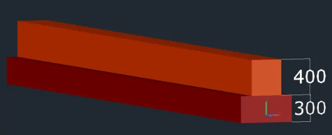
Go to the top view and create a profile for the foundation step in the 2D plan and copy and place it in the 3D plan using the snap tool.
Create an area with the "BO" command. Pull it out by 400 mm.
Create the profile again and position it so that the center of the 2D profile coincides with the 3D object.
Create an area and extend it by 400mm.
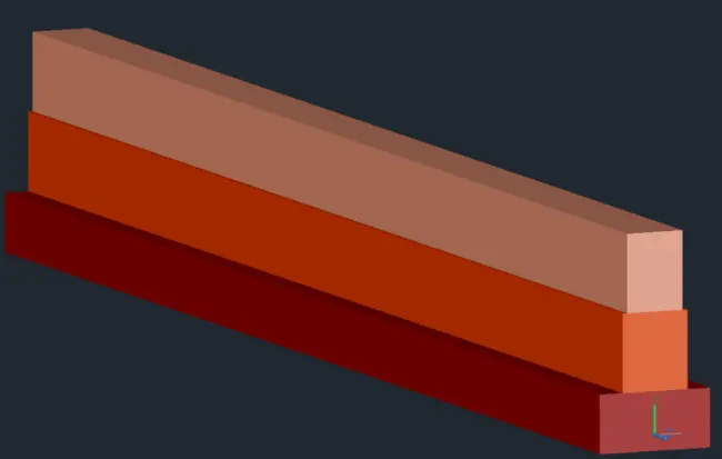
Now create a foundation profile in another layer and place it on top of the 3D model. Pull it up to a height of 550 mm.
Step 5:
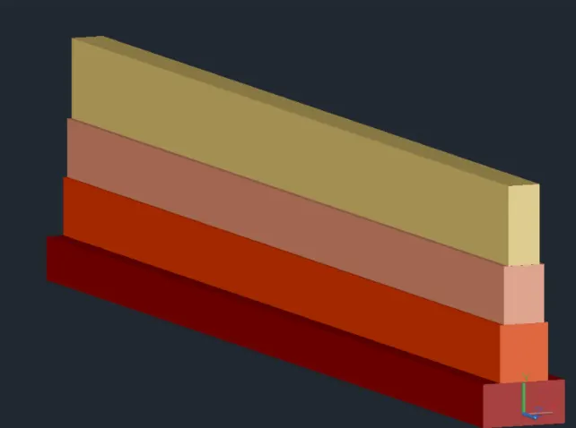
Creating a floor:
Create a rectangle for the floor and extrude it to a height of 50mm.
Step 6:
Creating a wall:
Now create a profile for the wall on both sides of the door. Copy it and place it in the 3D model and pull it up at 3300mm.
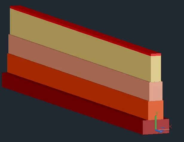
Step 7:
Creating a translation beam:
Create a rectangular profile at the top. Move it with the move command @ 0,0, -1050.
Extrude it at a height of -150 mm.
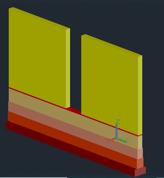
Step 8:
Creating the top of the wall:
Create a rectangle on the top surface. Pull up to a height of -1050 mm.
Use the Unite command to create the extruded part as part of the wall.
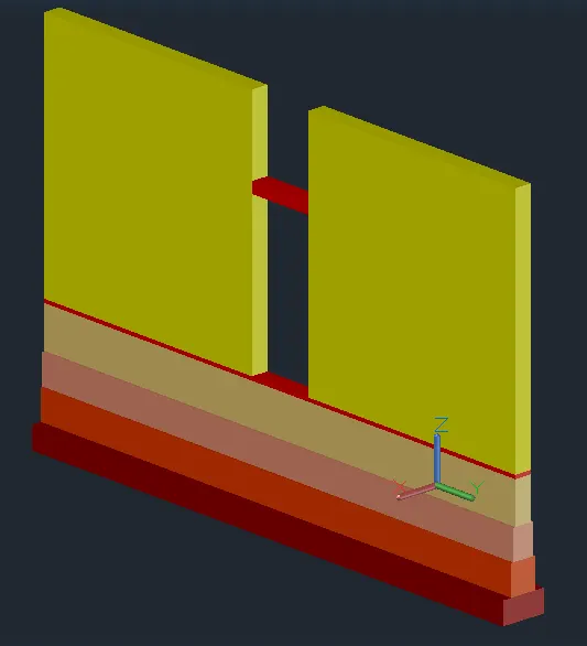
Step 9:
Creating a shadow:
Keep the UC on the side surface. Draw a horizontal line from the bottom of the lintel and then a vertical line 50mm up.
On the other side, draw a vertical line 100mm upwards and then connect these two points 50 and 100.
Group it into one entity. Create an area with the boundary command by placing the UC on the side face of the door frame.
Push it towards the side up to the opening.
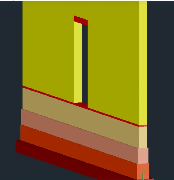
Step 10:
Creating the top plate:
Create a rectangular profile on the top of the wall. Pull it out by 150 mm.
Step 11:
Creating a window sill and trim:
Create a window sill 150 mm wide and 750 mm high. On the 3D model, create a rectangle of 7500 mm and 150 mm.
Extend it by 750 mm.
For handling at the side view point, draw UC and draw a line of width 40 mm from the parapet with a projection of 60 mm. Create a region with the bo command
Draw a line at the top.
Use the drag option, select the projection and then the line.
Step 12:
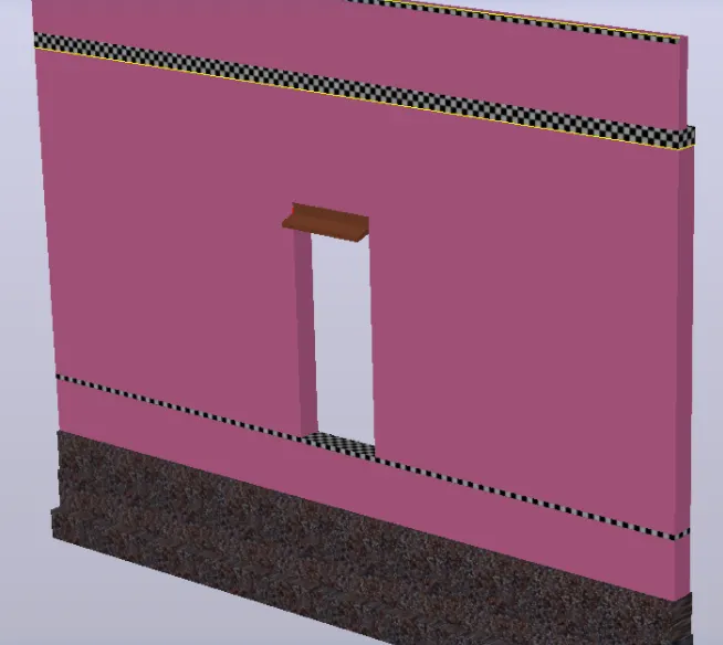
Rendered view:
Go to the Visualization tab and select the material viewer.
Select a stone as the base. Choose a color for the wall.
For floor, select from floor. Select each object and assign to selection
leave shadows on. Create a cylinder and put a distant light.
Then click render or "RR" command.
Result:
RESULT:
A 3D view of the building is created.
A 3D view of the building facade is created.
A 3D isometric view of the staircase is created.
A 3D view and a rendered view of the footer spread will be created.