Creating 3D Isometric view of various structural elements in AutoCAD
1) Create a 3D Isometric View of the building with plan and elevation given.
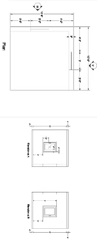
Ans : Open new file in autocad ,
change the workspace in 3D and draw the wall section and given
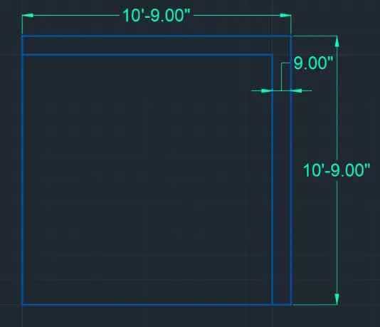
Draw windows byusing line command
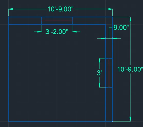
Now extrude the wall upward 10'10"
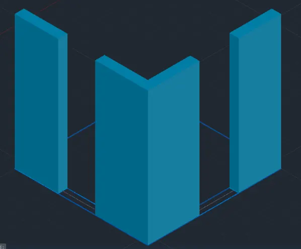
Draw rectangle at the top fo window
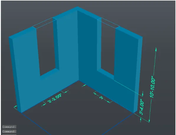
EXtrude those rectangular below upto lintel level
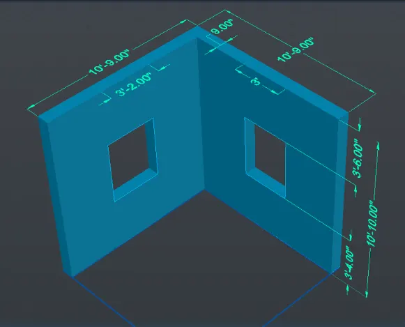
Draw a rectangle of dimension @3’,4’
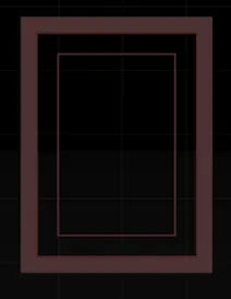
Offset the rectangle to inside to distnce of 3”
Offset the offset rectangle to inside to distnce of 4”
Start the boundary command and click on pick points
Click inside the window frame area and press enter
Start SUBTRACT command
Select the bigger region and then select the smaller regions to subtarct them
Follow the same procedure for all the three boxes as shown in figure
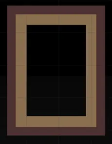
Apply blue color for glass appearance
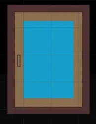
Extrude panel part backward
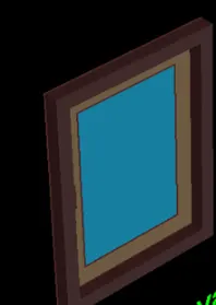
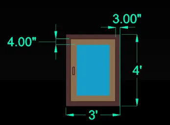
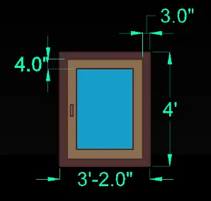
Now put the window on wall portion by using copy command
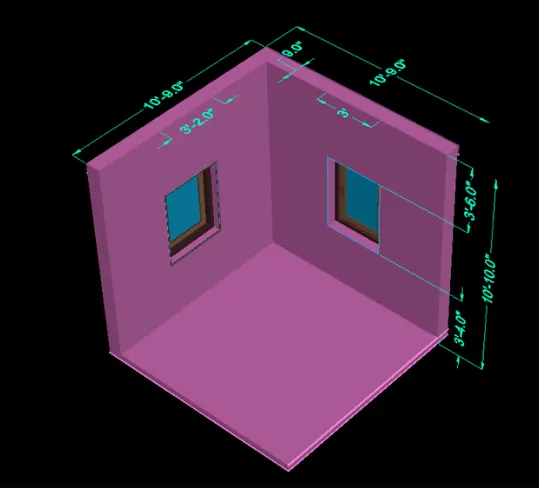
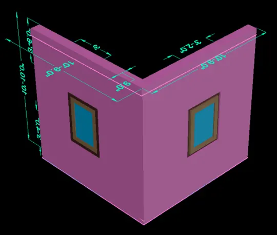
------------------------------------------------------------------------------------------------------------------------------------------
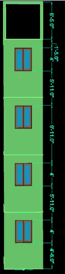
2) Create the 3D View of the Building Façade as given in the plan and elevation. Also, see the detail of the window.
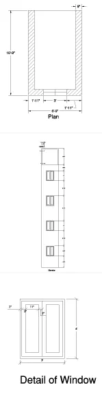
Ans : In the new file of autocad draw the plan by using line , trim , copy , move , fillet , offset commands
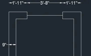
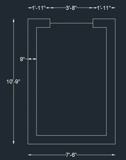
Now use region command and make it a unit and extrude it and substract the part of window from wall
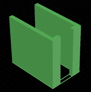
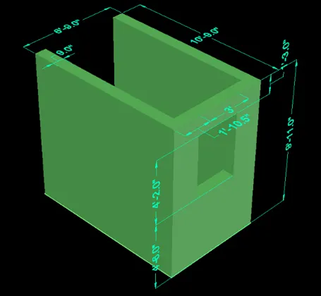
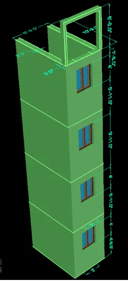
After extruding copy upto 4 floors , wirespace view
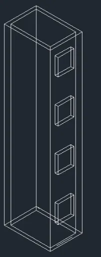
Now draw the line plan for window by using line , offset , trim commands
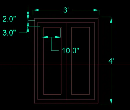
Apply solid hatch to panel
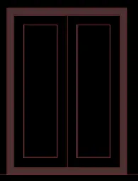
After extruding substarct the inner rectangle
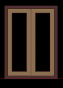
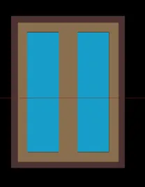
Draw this part on top
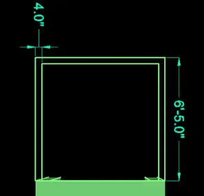
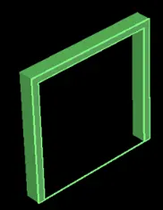
Now put window on there place by using copy command
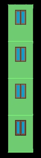
After this put upper part properly by using 3Dmove command
-------------------------------------------------------------------------------------------------------------------------------------------------------------------
3) Create the ismoteric 3d view of a stair with railing as shown in the plan and elevation. Assume the size of the balustrades and the hand rails.
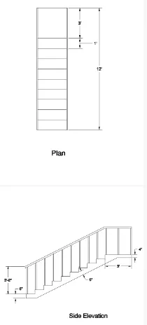
Ans : By using line , trim , copy , offset command draw

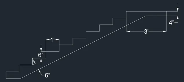
Now extrude the steps
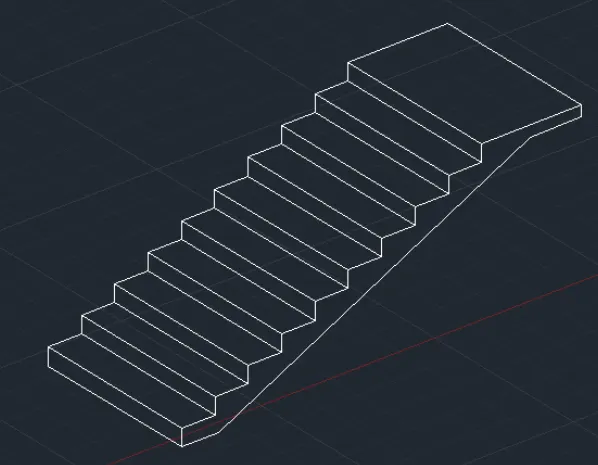
Next we draw the railing using the circle command and sweep command.
Next we show the stairs in the side view using the 3drotate command as shown in the below figure.
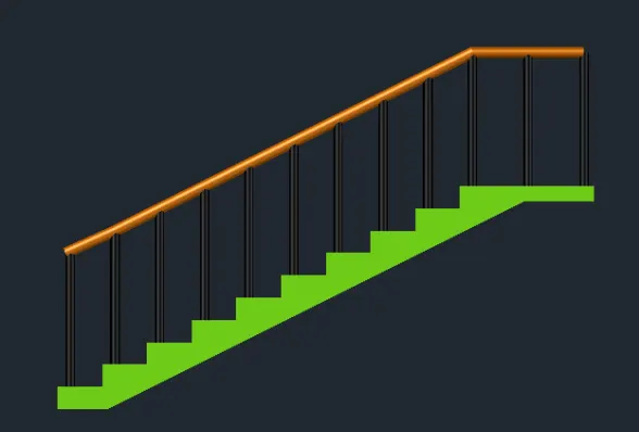
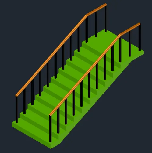
Final view of staircase is as follows

--------------------------------------------------------------------------------------------------------------------------------------------------------------
4) Create the 3D view of a Wall with spread footing . Create the Door opening only. Assume the size of the parpaet and the coping. See the plans and elevation for the details. Also, create a rendered view of the model with materials as of your choice.
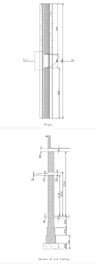
Ans : Draw a rectangle of dimensions 670X7500 , Offset the rectangle to inside to a distance of 120mm and Offset the offset rectangle inside to distance of 50mm twice.Explode all the offset rectangle
Delete the top and bottom edges of the exploded rectangles
Extend all the rectangle to top and bottom edges of outer rectangle.
At the end select the individual lines and change their layers respectively
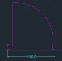
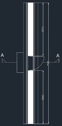
Next we draw the 3d isometric view of the wall with spread footing using the extrude command as shown in the below figure.
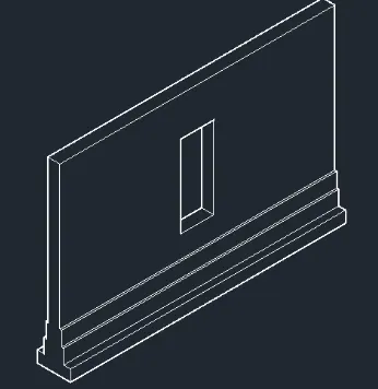
Draw a line of certal length
Offset the line to bottom 25mm
Offset the last offset line bottom to distance of 100mm
Change the current layer to Wall
Draw a rectangle of dimension 230X 3300 from the top left edge of Ground level
Change the current layer to roof level
Draw roof of thickness 150mm as shown in figure
Draw a Parapet wall of height 600mm as shown in figure
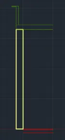
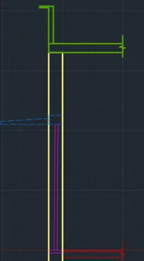
According to dimensiond we draw footing by simply using line mirrior and offset command
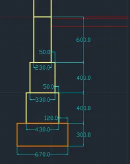
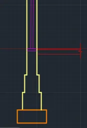
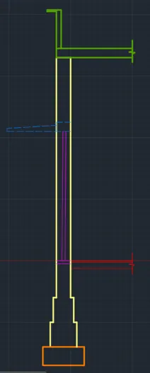
Now create boundaries and each boundry is put in respective layer
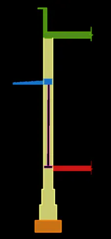
Extrute the section to give it wall view
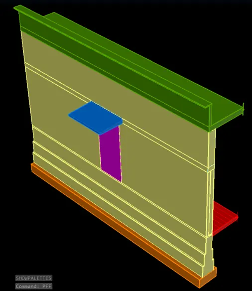
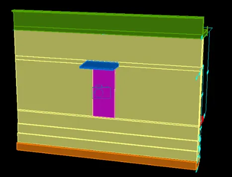
Put the window properly
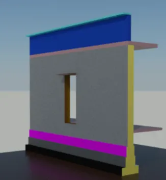
Rendering
-------------------------------------------------------------------------------------------------------------------------------------------