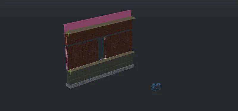
Creating 3D Isometric view of various structural elements in AutoCAD
1. Create a 3D Isometric View of the building with plan and elevation given.
AIM:
To create a 3D isometric view of the given building with plan and elevation.
INTRODUCTION:
- An isometric view is a two-dimensional representation of a three-dimensional object, aligned to three axis. Lines on the drawing that are parallel to one of the axes are always drawn exactly to measure or scale.
- Isometric view uses segments of equal length to create three dimensional images on a two dimensional surface, Iso means - equal metric means - measure
- Isometric view is used in technical drawing to show a three- dimensional object on a two-dimensional surface like a sheet of paper
- In isometric drawing the object appears as if it is being viewed from above from one corner with the axes being set out from this corner point.
- An isometric view is drawn as a parallel view where the lines do not coverage on each other, lines are not hidden in isometric view. In isometric view two sides are inclined at 60 degree to the height of axis.
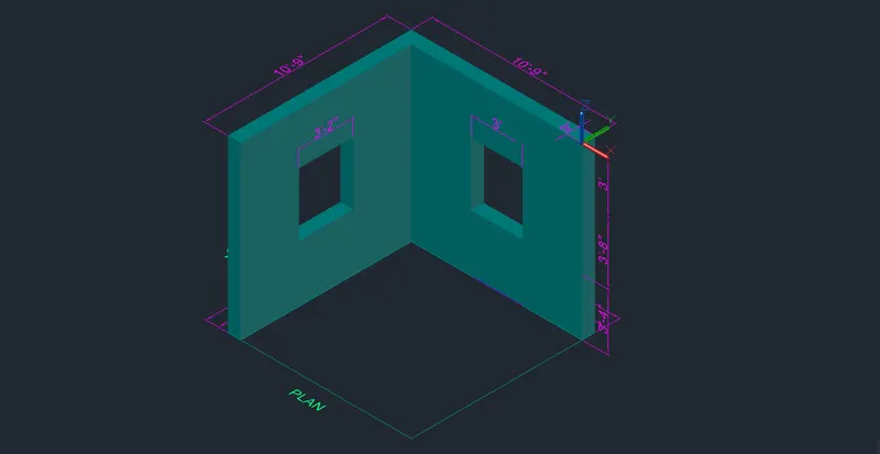
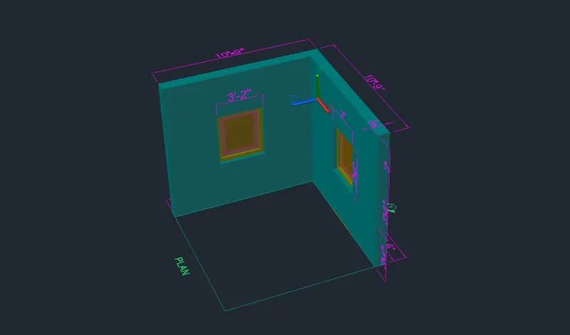
- A plan view of wall of two elevation views of window on both sides are given and they are converted into a 3D model. Two window openings on both sides are given with details regarding frame and also the thickness of bottom and top floor is given as 4'' and 6'', height as 10'.
COMMANDS USED:
- Line
- Units
- UCS
- Dimlinear
- Rectangle
- Region
- Extrude
- Subtract
- 3D face
- 3Dorbit
- Hide
- Explode
- 3Dmirror
- 3Dmove
- Copy
- Solidedit
- Union
- Boundary
- Erase
- Explode
PROCEDURE:
STEP1
- Open AutoCAD with imperial system (Feet and Inches)
- In command prompt type "UNITS" set the units as engineering and precision to 0'-0''.
- Then type "LIMMAX" in command box and set the maximum upper limits as 500',500'.
- Then change the work space settings of autocad from Drafting and Annotation to 3D modelling.
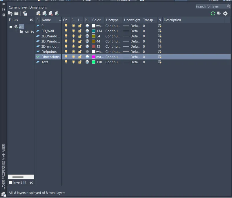
- By using command "LA" open the layer properties and create a new layer by clicking on new layer, each objects are named as per the names used in standard constructions, the created layers are as follows,
STEP2
- Change the current layer to 3D_Wall with 2D_Wireframe
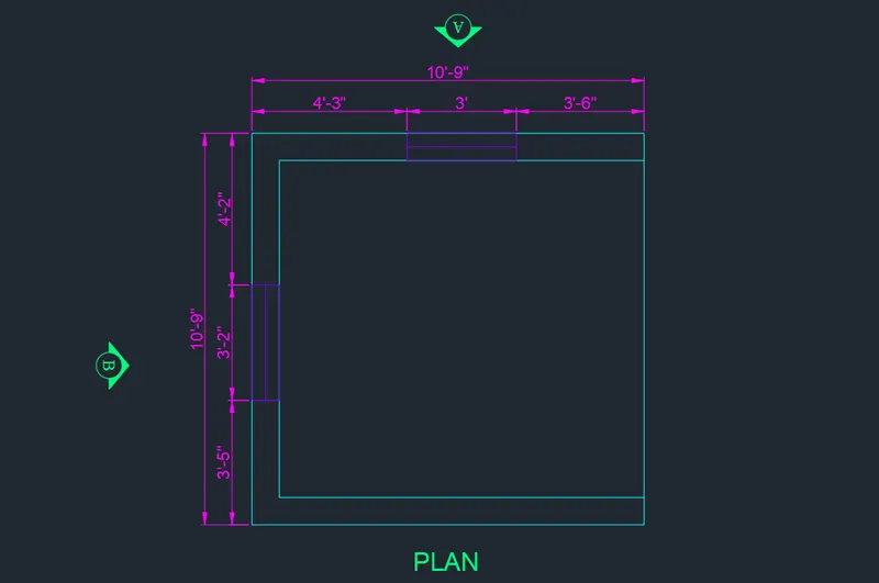
- By using "REC" command draw a rectangle of dimension about 10'9'' x 10'9'' at any point on screen
- In command prompt type "O" for offset and offset the created rectangle towards inner side of about 9'' as wall thickness
- Then in layer properties set the 3D_Window as current layer
- The windows are drawn from the right end at 3'6'' far the window is drawn for 3' width, similarly on left side thw window is drawn for 3'2'' at 3'5'' from bottom end
- By using Dimstyle command new style is created and the font height and text height are assigned, then By "DIMLIN" and "DCO" commands dimensions and text are made along with their respective layers.
STEP3
- In command type "ERASE" and erase the left and bottom line and extend them towards edges as shown in figure
- Then change the current layer to 3D_Wall_Frame
- Create a region of each wall by using command "REG"
- Then by using "EXT" command extrude the region wall to a height of 10'10'' on each side
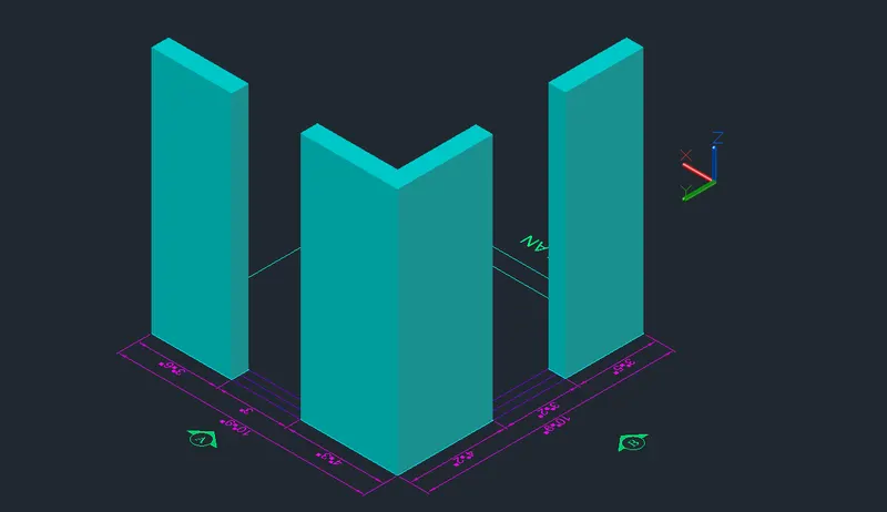
- And also by using the command "M" move the window to a height of 3'4'' on each side of the wall and create as region and extrude it.
- Draw rectangle at top of both window openings and change them to boundaries by comman "BO"
- Type UCS and click on face and select the face having 3' wide window
- Draw a rectangle from bottom part of window with dimensions 3' and 3'8''
- Type UCS and click on face and select the face having 3'2'' wide window
- Draw a rectangle from bottom part of window with dimensions 3'2'' and 4'
- Change the ucs back to world, and extrude the rectangle drawn at top side to top edge of window
STEP4
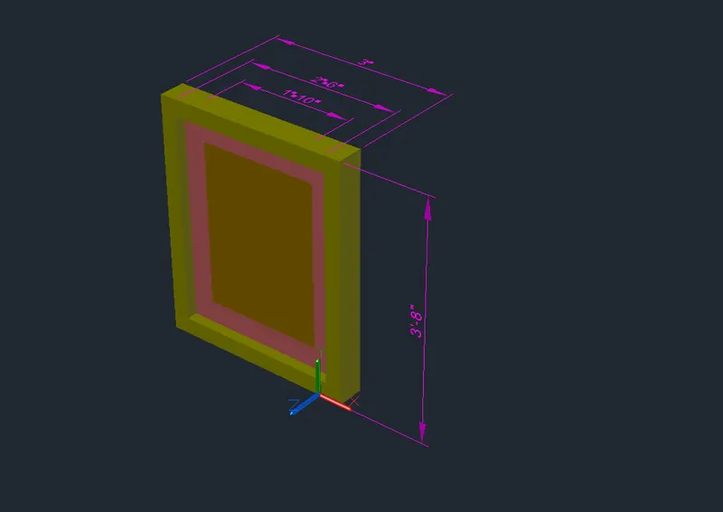
- To create window of elevation A ,change the current layer in layer properties change to 3D_Window_Frame
- Type ucs and click on face and select the face having 3' wide window
- Draw a rectangle of dimension 3',4' and offset the rectangle to inside at distance of 3''
- Then again offset the last offseted rectangle towards inner side at 4'' distance
- Type "BO" in command prompt and create a boundary at outer frame
- By using command "EXT" extrude the created region to distance in -z axis at 5''
- Similarly create a boundary for rest of the rectangles
- Change the current layer to 3D_Window_Mulion
- create a region for inner rectangle as mulion keep the rectangle 2'' in -z axis
- By using command "EXT" extrude the created region to distance in -z axis at 3''
- Start "SUBTRACT" command and select the bigger region and then select the smaller region to subtract them.
- Change the current layer to 3D_Window_glass and create a boundary
- Then extrude the boundary to 3'' in -z axis
- The dimensions are marked as shown in figure
STEP5
- All the layers are extrded to give window projection look as shown
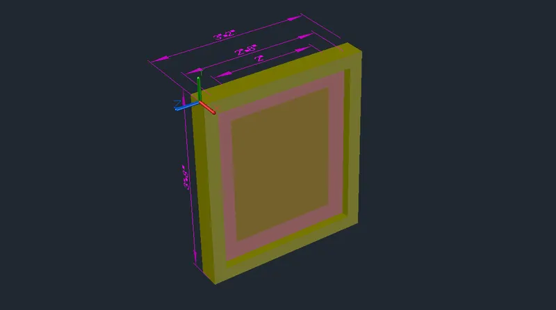
- Windows at elevation B,
- Type ucs and click on face and select the face having 3'2'' wide window
- Draw a rectangle of dimension 3',4' and offset the rectangle to inside at distance of 3''
- Then again offset the last offseted rectangle towards inner side at 4'' distance
- Type "BO" in command prompt and create a boundary at outer frame
- By using command "EXT" extrude the created region to distance in -z axis at 5''
- Similarly create a boundary for rest of the rectangles
- Change the current layer to 3D_Window_Mulion
- create a region for inner rectangle as mulion keep the rectangle 2'' in -z axis
- By using command "EXT" extrude the created region to distance in -z axis at 3''
- Start "SUBTRACT" command and select the bigger region and then select the smaller region to subtract them.
- Change the current layer to 3D_Window_glass and create a boundary
- Then extrude the boundary to 3'' in -z axis
- The dimensions are marked as shown in figure
RESULT:
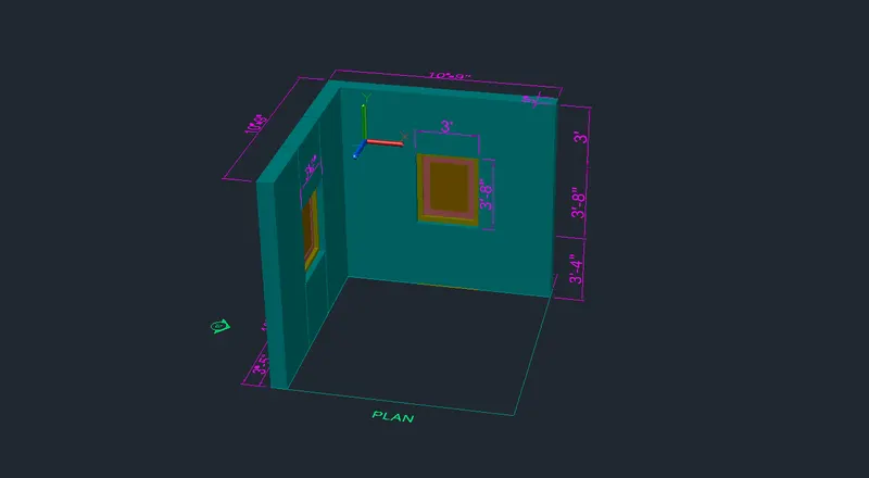
The given 3D isometric view of a building with plan and elevation is drawn as shown.
2. Create the 3D View of the Building Façade as given in the plan and elevation. Also, see the detail of the window.
AIM:
To draw the 3D building Facade as given in the plan and elevation
INTRODUCTION:
- An isometric view is a two-dimensional representation of a three-dimensional object, aligned to three axis. Lines on the drawing that are parallel to one of the axes are always drawn exactly to measure or scale.
- Isometric view uses segments of equal length to create three dimensional images on a two dimensional surface, Iso means - equal metric means - measure
- Isometric view is used in technical drawing to show a three- dimensional object on a two-dimensional surface like a sheet of paper
- In isometric drawing the object appears as if it is being viewed from above from one corner with the axes being set out from this corner point.
- An isometric view is drawn as a parallel view where the lines do not coverage on each other, lines are not hidden in isometric view. In isometric view two sides are inclined at 60 degree to the height of axis.
- A plan view of wall and two elevation view one is the window details and other is floor level elevations are given and they need to convert into 3D models
COMMANDS USED:
- Line
- Units
- UCS
- Dimlinear
- Rectangle
- Region
- Extrude
- Subtract
- 3D face
- 3Dorbit
- Hide
- Explode
- 3Dmirror
- 3Dmove
- Copy
- Solidedit
- Union
- Boundary
- Erase
- Explode
PROCEDURE:
STEP1
- Open AutoCAD with imperial system (Feet and Inches)
- In command prompt type "UNITS" set the units as engineering and precision to 0'-0''.
- Then type "LIMMAX" in command box and set the maximum upper limits as 500',500'.
- Then change the work space settings of autocad from Drafting and Annotation to 3D modelling.
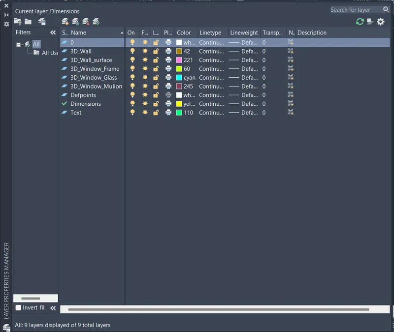
- By using command "LA" open the layer properties and create a new layer by clicking on new layer, each objects are named as per the names used in standard constructions, the created layers are as follows,
STEP2
- Keep the view cube on top and 2D_wireframe
- In layer properties set the wall as current layers
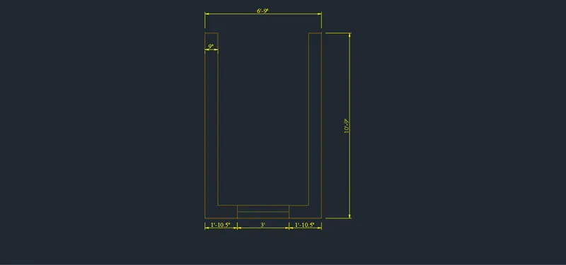
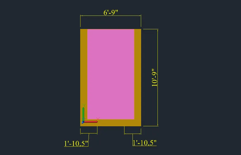
- Create a rectangle of dimension 6'9'' x 10'9'' at any point on the screen
- Offset the rectangle to inside to distance of 9'' as wall thickness.
- And create the window at 3' as shown
STEP3
- By using "EXPLODE" command explode the rectangle and erase the top line and extend towards the edges
- Change the current layer to 3D_Window_Frame
- Create the window opening of dimensions 3' wide as shown in figure
- The dimensions are set by using DIMSTYLE command then dimension and texts are marked
- Change the view to 3d by clicking on home button of view cube set ucs to world
- Set the view style to REALISTIC
- Create boundaries for walls using "BO" command
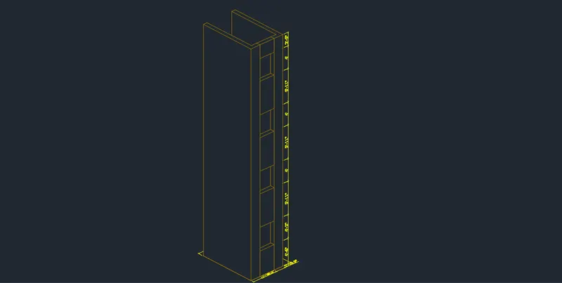
- In command prompt type "EXT" and extrude the walls to total height of 40'10'' from bottom to top.
STEP4
- Create a boundary region over the window lines by "BO" command
- Extrude the boundary to a height of 4'6'' by "EXT" command
- Draw a rectangle on top of the window opening using rectangle command
- Change the rectangle to a region by "REG" command
- extrude the region to distance of 1'3'' to below and then window opening is created as shown
STEP4
- To create elevation windows change the current layer to 3D_Window_Frame
- Type ucs and click on face and select the face having 3' wide window
- Draw a rectangle of dimension 3' , 4' offset the rectangle to inner side for distance of 2''
- Offset the last offseted rectangle to distance of 3'', then draw a centre line connecting midpoints
- In command prompt type "BO" and click on pick points and click inside of the window frame area and press enter
- Command "Su" to subtract click on the bigger region to smaller region

- Then change a current layer to 3D-Window_Mulion in layer properties
- Command boundary and click on pick points, click inside the window mulion and press enter
- Then by using subtract command "SU" subtract the bigger region to smaller region
- Similar way change the current layer to 3D_Glass in layer properties
- Create a region of it then subtract the outer to inner region
- All the layers are extruded by using "EXT" command to show window projection
- Change the view of window and place them in to plan view

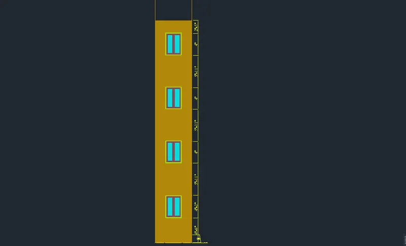
- Keep the view cube at front position and place the created windows over all window openings
- The over all building view from front is shown
STEP5
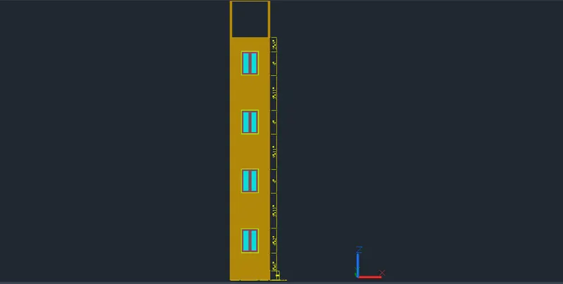
- Create the top part of the drawing using 4'' wall with height 6'5'' from top
- Create a boundary using "BO" command for the wall
- By using "EXT" command extrude the boundary to 9'' as shown in elevation
- using 3DO command to view the front elevation as shown in below figure
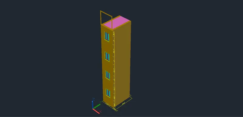
- Put the building facade in isometric view using 3dorbit command
RESULT:
The given 3d isometric view of the building facade is drawn as per plan and elevation.
3. Create the ismoteric 3d view of a stair with railing as shown in the plan and elevation. Assume the size of the balustrades and the hand rails.
AIM:
To create the 3D isometric view of a stair along with railing as shown in the plan and elevation.
PROCEDURE:
STEP1
- Open AutoCAD with imperial system (Feet and Inches)
- In command prompt type "UNITS" set the units as engineering and precision to 0'-0''.
- Then type "LIMMAX" in command box and set the maximum upper limits as 500',500'.
- Then change the work space settings of autocad from Drafting and Annotation to 3D modelling.
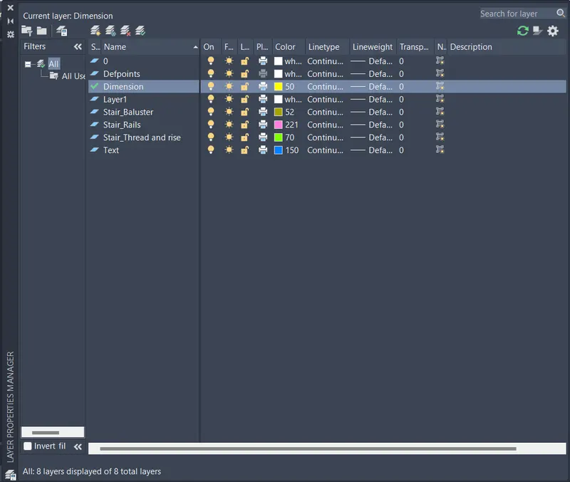
- By using command "LA" open the layer properties and create a new layer by clicking on new layer, each objects are named as per the names used in standard constructions, the created layers are as follows,
STEP2
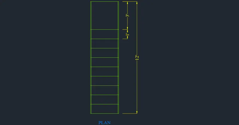
- In layer properties change the current layer to stair_thread and rise
- Draw a rectangle of dimensions 3’X12’
- Explode the rectangle by using "EXPLODE" command
- Offset the side edges to inside to a distance of 1”
- Offset the bottom edge to upside 12 times to a distance of 1’ as shown in figure
- Set the dimension style na dfont style using "DIMSTYLE" command
- The staircase and the dimensions are made by keeping their respective layer as current layer
STEP3
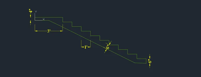
- Change the view to 3d by clicking on home button of view cube and chance the view to right view
- In command prompt type ucs and set the ucs to Right by clicking face and place over the plan
- Start line command and draw a vertical line of length 6”
- Draw a horizontal line of length 1’ the threader and riser are created
- Repeat the same process for 12 times to draw 12 steps
- After reaching 12 steps draw a landing of length of 3’
- Draw a line of 1’ at the bottom step
- Draw a line of 6” at the top right edge of landing
- Draw a line of 1’6” backwards
- Draw a slab joining the lines
- Change the view to 3d by clicking on home button of view cube
- Set UCS as world
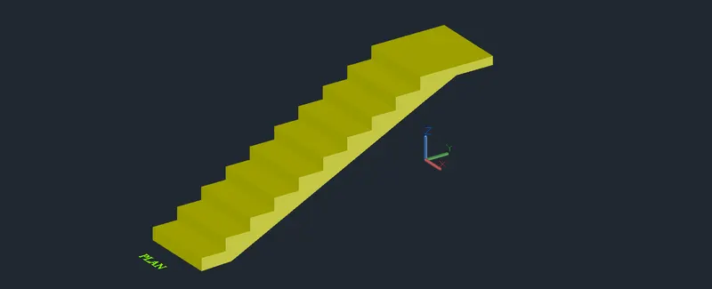
- Set the view style control as REALISTIC
- Create a region from the side view of the stairs
- Extrude the side view to a distacne of 3’ as shown in figure
STEP4
- To create hand railings,
- Change the current layer to Stair_handrails
- Draw circle of diameter 1” with 2” offset from the top right edges of the first thread of staircase
- Change the circle into a region
- Extrude the region to a height of 3’ as shown in the figure
- Change the current layer to Stair_handrails_Stand
- Draw a handrail stand at the bottom with dimension 2” and extrude as shown in figure
- Using copy command copy all the hand rail components on all stairs with same offset as shown in figure
- Copy the same to the other side as shown in figure
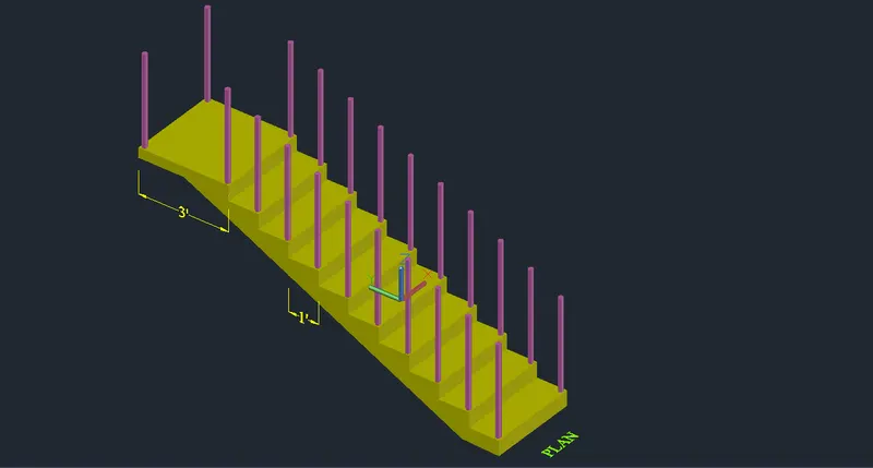
RESULT:
The isometric 3D view of stairs and railings are drawn as in plan and elevation.
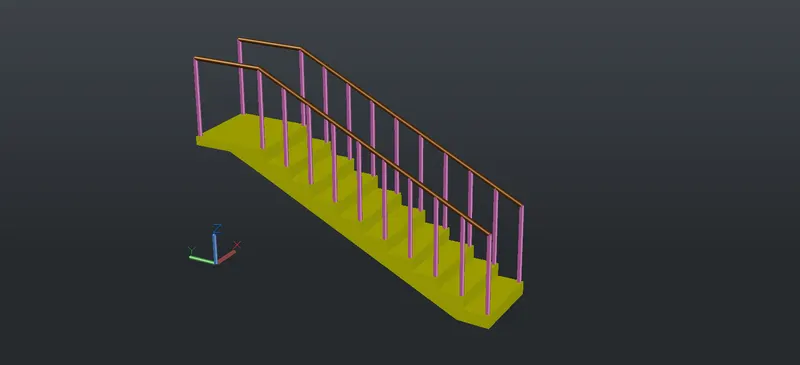
4. Create the 3D view of a Wall with spread footing . Create the Door opening only. Assume the size of the parpaet and the coping. See the plans and elevation for the details. Also, create a rendered view of the model with materials as of your choice.
AIM:
To create the 3D view of a Wall with spread footing And need to create a rendered view of the model with materials
PROCEDURE:
STEP1:
- Open AutoCAD with metric system (Millimeters)
- In command prompt type "UNITS" set the units as engineering and precision to 0-0.
- Then type "LIMMAX" in command box and set the maximum upper limits as 5000,5000.
- Then change the work space settings of autocad from Drafting and Annotation to 3D modelling.
- By using command "LA" open the layer properties and create a new layer by clicking on new layer, each objects are named as per the names used in standard constructions, the created layers are as follows,
- Change the workspace setting of AutoCAD from ‘drafting and annotation’ to ‘3D Modeling’
- Creating Layers
- Open Layer properties and create new layers by clicking on new layer or right click on any layer and select new layer to create new layer
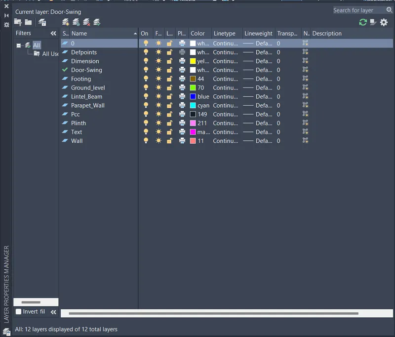
STEP2
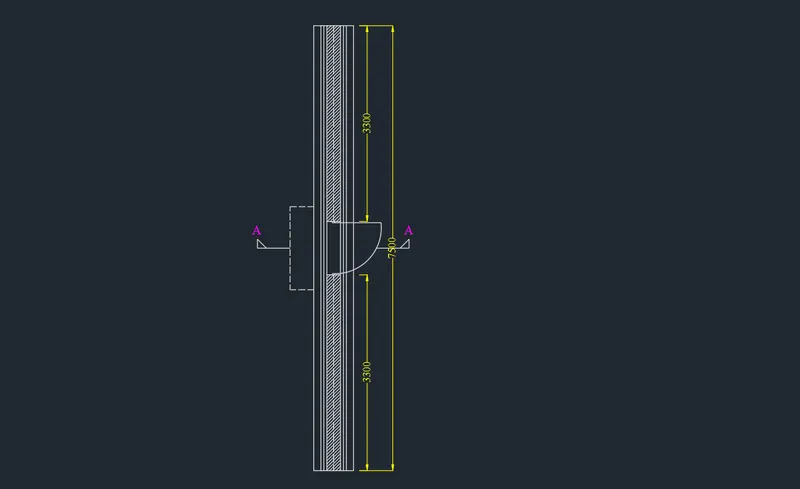
- To Creating 2D Plan View of wall with spread footing
- Change the current layer to wall in layer properties
- Draw a rectangle by using REG command of dimensions 670X7500 mm
- Offset the rectangle to inside to a distance of 120mm
- Offset the offset rectangle inside to distance of 50mm twice.
- Explode all the offset rectangle by using "EXPLODE" command
- Erase the top and bottom edges of the exploded rectangles
- Extend all the rectangle to top and bottom edges of outer rectangle.
- At the end select the individual lines and change their layers respectively
- Then to create a door , draw a rectangle of dimension 50X100mm
- Draw another rectangle with dimensions of 50X50mm
- Draw a line of length 850mm from the edge
- Draw an arc line of the door swing
- Convert the door into block by using command "B" for block
- Create the door opening of 900mm at the middle
STEP3
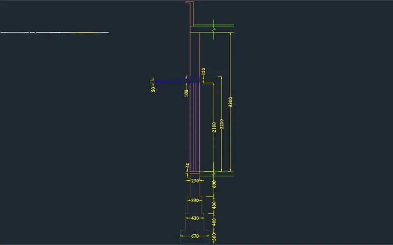
- Click on the Front view of the view cube and zoom for better view
- Change the ucs to front
- Change the current layer to G.L.
- Draw a line by using "L" command to certain length
- Offset the line to bottom 25mm
- Offset the last offset line bottom to distance of 100mm
- Change the current layer to Wall
- Draw a rectangle of dimension 230X 3300 from the top left edge of Ground level
- Change the current layer to roof level
- Draw roof of thickness 150mm as shown in figure
- Draw a Parapet wall of height 600mm as shown in figure
- Footing Layers
- Draw a rectangle of dimension 230X600, below the floor level as shown in figure
- Draw a rectangle of dimension 330X400, below the first level as shown in figure
- Draw a rectangle of dimension 430X400, below the second level as shown in figure
- Change the current layer to Footing
- Draw a rectangle of dimension 670X300, below the third level as shown in figure
- Trim the unnecessary edges
- Change the current layer to door
- Draw a line along the length of the door of 230mm at the ground level
- Offset the line to belwo to distanc of 50mm below the ground level
- Offset the line to distance of 2100 to above
- Change the current layer to Door Shade
- Draw the door shade as shown in figure
- The end result of this step is as follows
STEP4
- Drawing 3D View of section
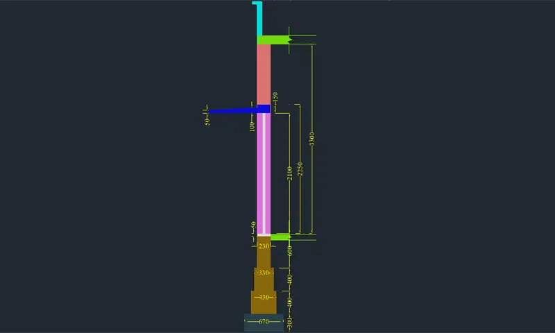
- For creating the 3D view initially boundaries are created by "BO" command
- Each boundary is created with its respective layer as current layer as shown in the following figure
STEP5
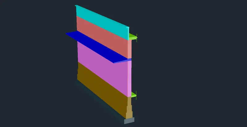
- Extrude all the created region by using command "EXT" towards -x axis
- The created boundaries are to be extruded to a distance of 7500mm
- Select the boundaries by changing their respective current layer
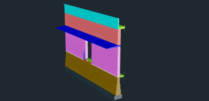
- Door opening is added by drawing a rectangle at the door locaton from the plan view
- Then from the extruded part the door region is subtracted from the wall using "SU" subtract command
- Similarly door shade is created with the opening above
- After door shade remaining layer is extruded as shown in figure
STEP6
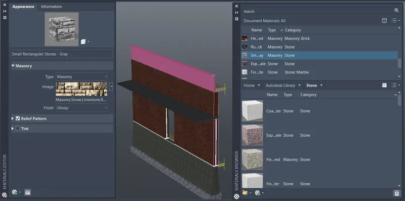
- Rendering is the process of giving realistic view of object
- Go to visualize > render > material browser
- Then go to autodesk liberary select the material to stone and add the selected material to document material
- Double click the stone to open the edit box, edit the stone scale so that it should fit in the footing or pcc and easy to visualize
- Then select the object in plan and select the stone material right click and click on assign to selection, the selected object now assigned to stone
- Like wise all the elements like footing, pcc, wall, parapet wall , groundlevel are rendered using material browser
STEP7
To create rendering with any of the saved views,
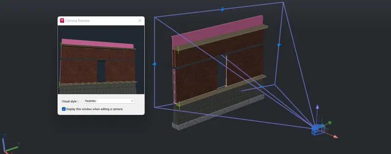
Firstly save the views by Visualize > new view > save as- view 1 > set current display
To place a camera first draw a circle of diameter 150mm and extrude the circle by using "EXT" command
Then go to Visualize tab > Camera > create new
click on create new camera and place the camera over the extruded circle
Set the camera view by adjusting the grips of camera
Now double click on the camera the saved view is shown in another dialogue box set the visual style to Realistic
RESULT:
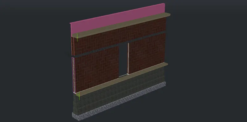
The 3D view of a Wall with spread footing is drawn along with rendering their views.
OVERALL RESULT:
1. The given 3D isometric view of a building with plan and elevation is drawn as shown.
2. The given 3d isometric view of the building facade is drawn as per plan and elevation.
3. The ismoteric 3d view of a stair with railing as shown in the plan and elevation are drawn.
4.The 3D view of a Wall with spread footing is drawn along with rendering their views.