Creating 3D Isometric view of various structural elements in AutoCAD
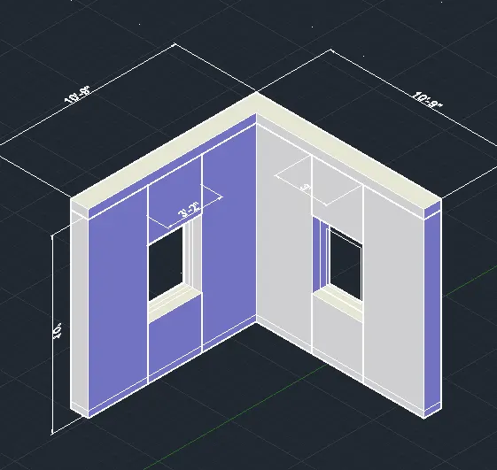
Creating 3D isometric view of the building with plan and elevation given
Procedure :
- Set units to engineering
- Using the line command the Plan, draw Elevation A and Elevation B
- Using the DIMLIM command the dimensioning was completed.
- Use extrude command to extrude the plan to 10'.
- Change the visual style control > Shaded
- Type REC and draw a rectangle on top of the window.
- Specify extrude height 3'
- In the similar way the other window was also created.
- Draw a rectangle of dimension 3,4'
- Offset the rectangle to inside to distnce of 3"
- Type SUBTRACT command
- Select the bigger region and then select the smaller regions to subtarct them.
Result
2.To create the 3D view of the building facade as given the plan and elevation
Procedure :
- Set units to engineering
- Using the line command the Plan, draw Elevation A and Elevation B
- Select 3D Modelling and visual style control to 2D wireframe.
- Using the line command the Plan is drawn
- Hatch with pattern was used to represent the walls.
- Click on the extrude option from from the home tab and extrude all but the windows slot
- Change the visual style control > Shaded
- Type REC and draw a rectangle on top of the window.
- Click on the extrude option from from the home tab.
- Click on the rectangle Specify extrude height 3' and press enter.
- Use the Extrude, Subtract and union command
- The top space is now added with another U shape plane .
- Extrude it to 6' as per elevation given
- Close the extruded elevation
Result
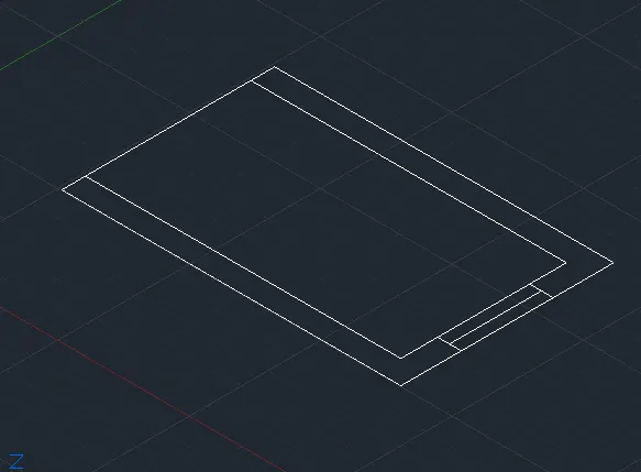
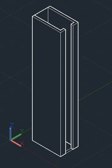
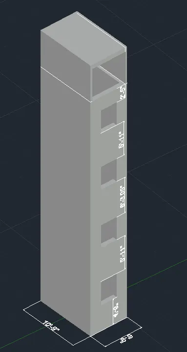
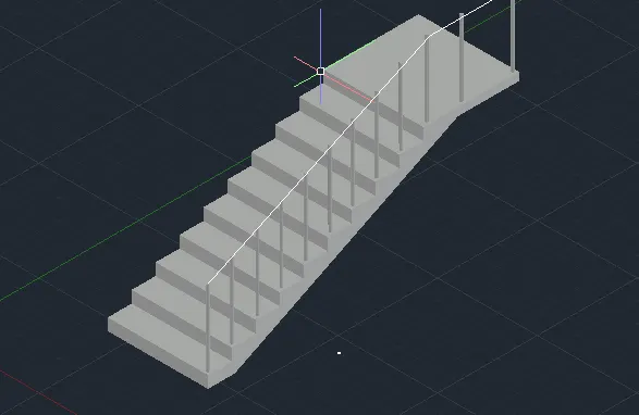
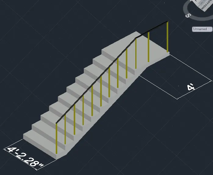
3.To create the isometric 3D view of a stair with railing aa shown in the plan and elevation
Procedure :
- Set units to engineering
- Using the line command the Plan, draw Elevation A and Elevation B
- Select 3D Modelling and visual style control to 2D wireframe.
- Using the line command the Plan is drawn
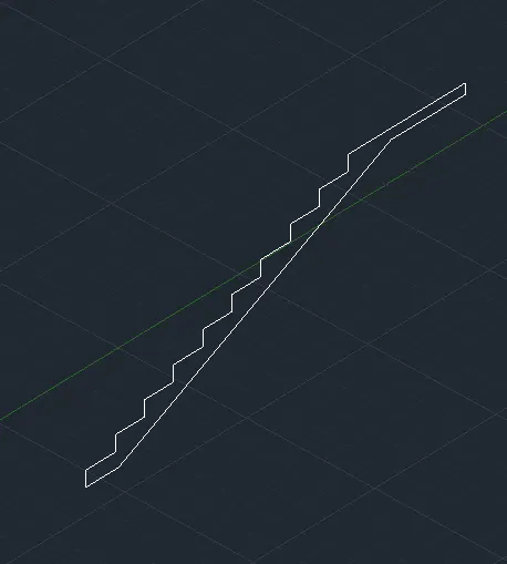
- Draw the stair plan and rotate it after ucs
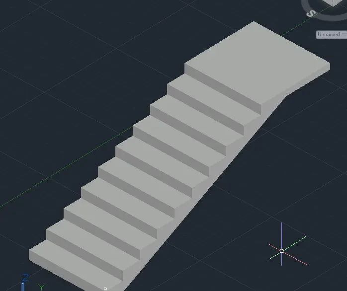
- Extrude it horicontally to 4'.
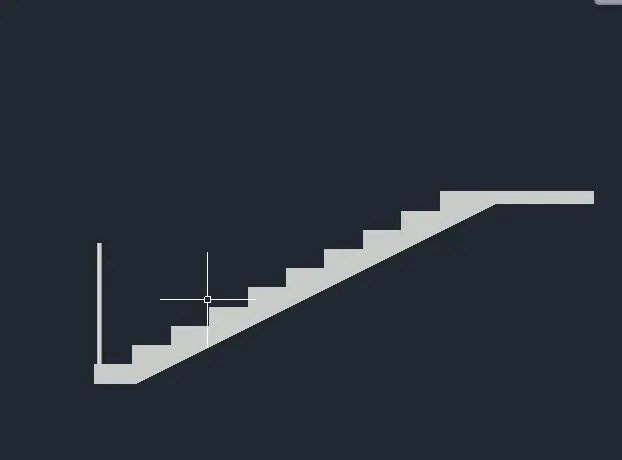
- Draw small circle in the strair and extrude it as per given plan
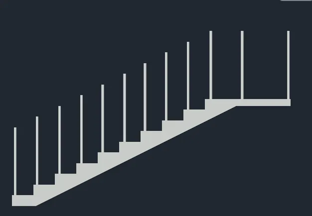
- Copy the railings for all stairs
- Draw line connecting all the top rails
- Draw another circle and using the SWEEP command the make the handle
- Use properties to change the colours
- Use dimensions to mark the dimensions
Result :
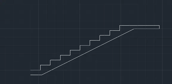
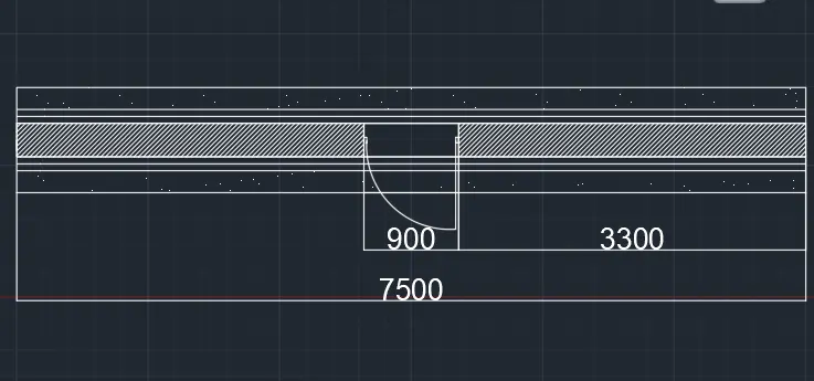
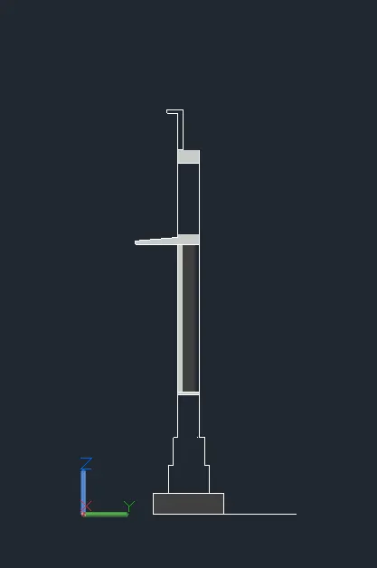
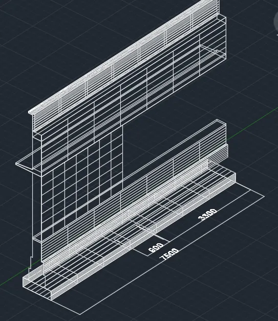
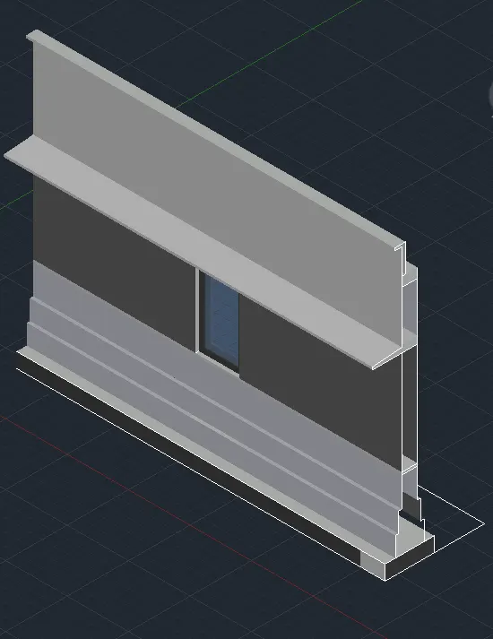
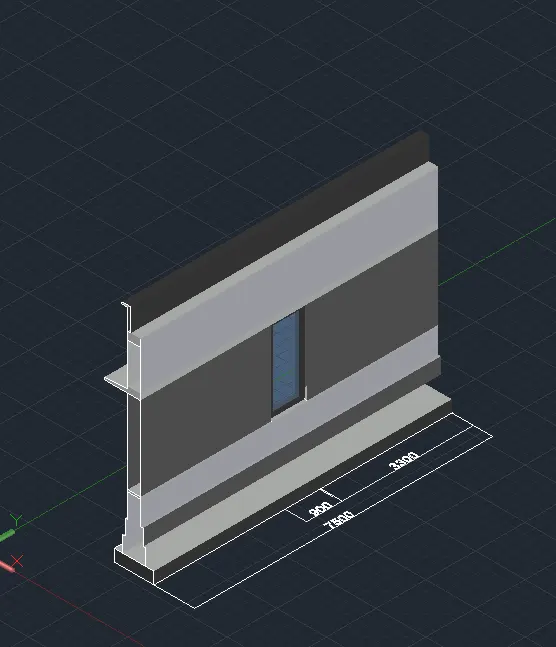
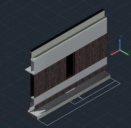
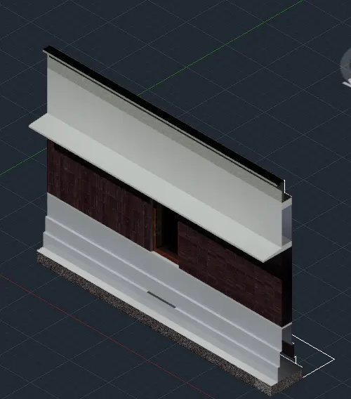
4.To create the 3D view of a wall with spread footing and door opening
Procedure :
- Set units to engineering
- Select3D Modelling and visual style control to 2D wireframe.
- Using the line command draw the plan
- Hatch texture and pattern
- Using the DIMLIM command to mark dimensions
- The south west ismetric view is made the default view.
- Use extrude command to extrude the footings
- Change the ucs to make the elevation of the wall and extrude it
- Leave slots for the window space
- Draw rectangles in the space and extrude it to fill the gap
- Use tool pallete to mark the material wiht repective materials
- Use rendercrop to render the selected area.
Result :