Creating 3D Isometric view of various structural elements in AutoCAD
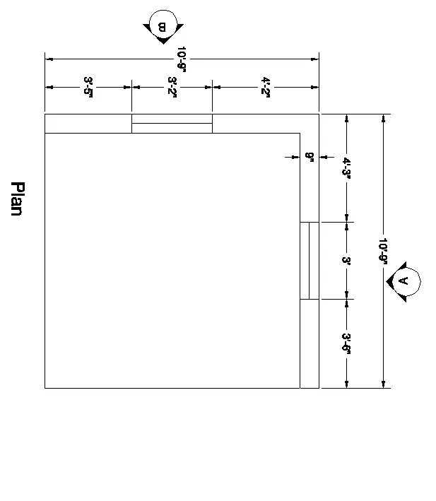
AIM: To create a 3D Isometric View of the building with plan and elevation given.
INTRODUCTION: Autocad is a software well designed for drawing 2D and 3D plans for the strutcure designs.
PROCEDURE:
1. CAD software is opened and new file is created.
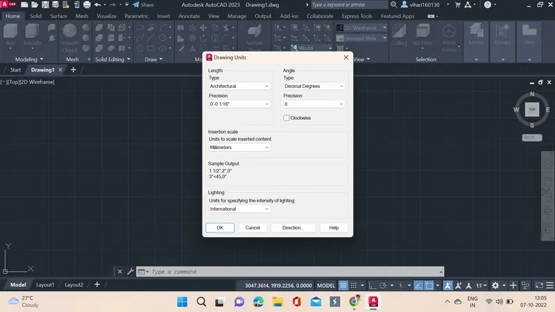
2. UN units command is used to specify the units.
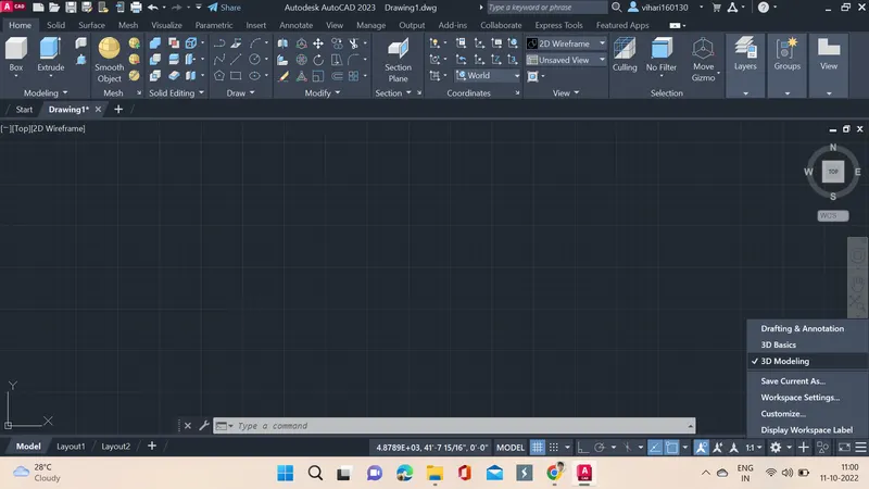
3. From settings 3D modeling is selected.
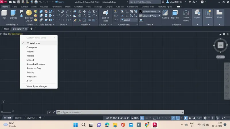
4. From visual style we select 2D wireframe.
5. REC command is used and dimensions are specified length is given as 10'9", and width is also given as 10'9" as per the figure.
6. next L command is used to draw the windows with the dimensions of 3'x9" on top, and another with 3'-2"x9" on left side.
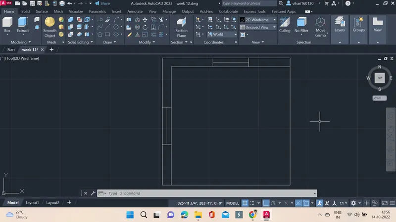
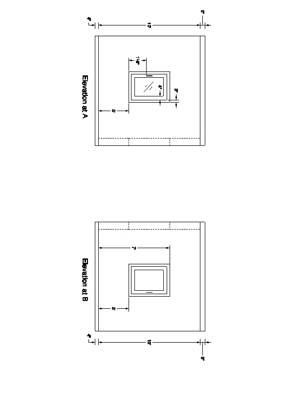
7. Elevation A is drawn using the rec and L commad.
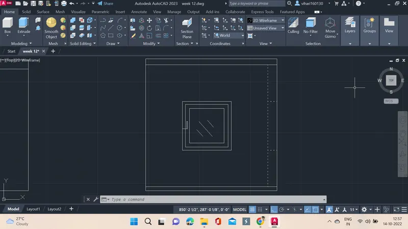
8. MI command is used and the elevation is mirrored to obtain elevation B.
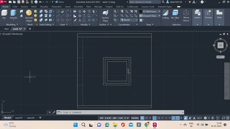
9. DIMSTY is used to specified the units for dimensions.
10. DIMLIN command is used to specify the dimensions.
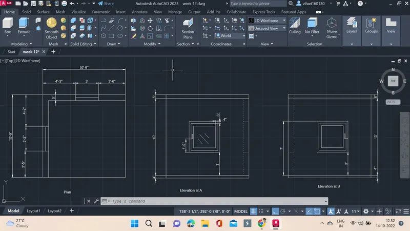
11. Southwest direction is clicked and boundary is specified and selected boundaries.
12. Extrude is used and the points are selected and height is specified as 10'.
13. Visual styles command is used and then shaded is selected.
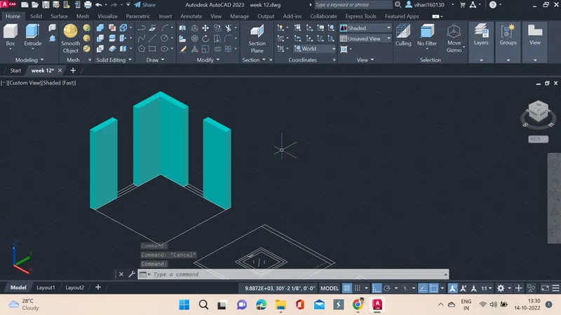
14. Using Rec command the windows are drawn and then the opening is created by erasing the window part.
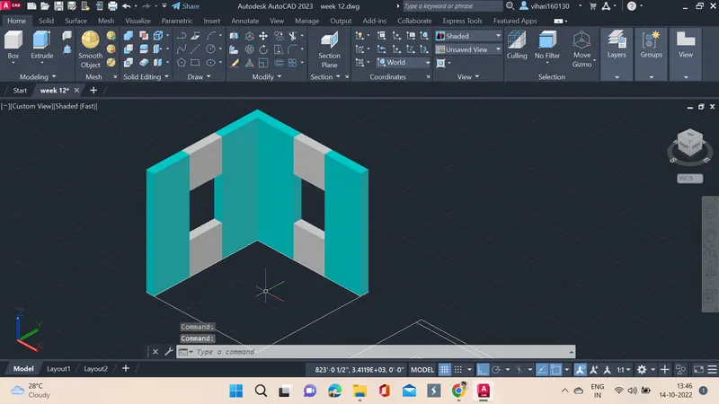
15. Now the rest wall is also closed using the extrude wirh height 10'.
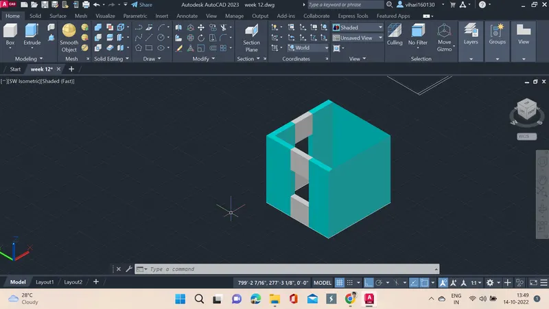
RESULTS: Using autocad 3D Isometric View of the building is drawn.
AIM: To create the 3D View of the Building Façade as given in the plan and elevation.
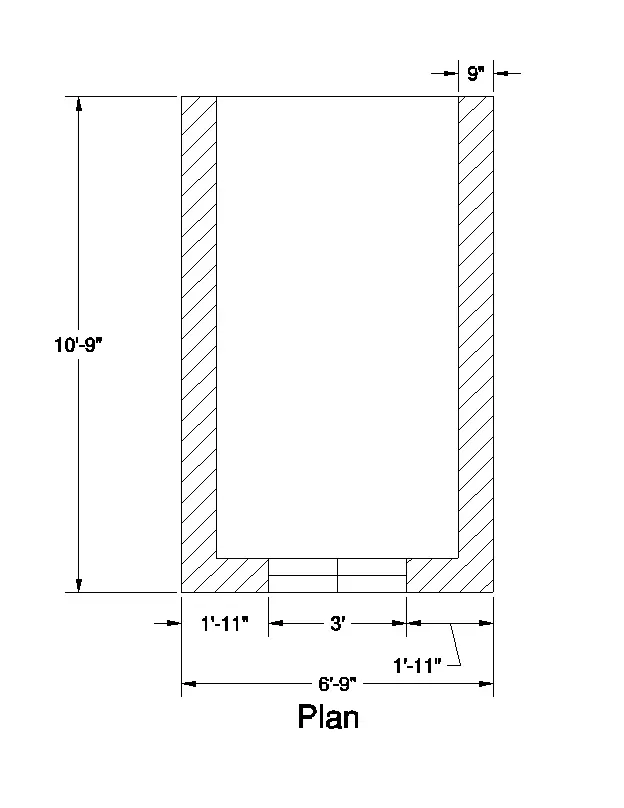
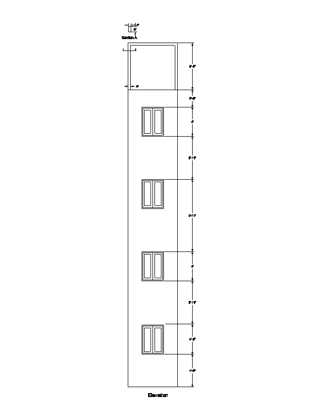
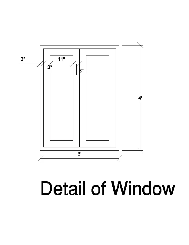
INTRODUCTION: Autocad is a software well designed for drawing 2D and 3D plans for the strutcure designs.
PROCEDURE:
1. CAD software is opened and new file is created.
2. UN units command is used to specify the units.
3. From settings 3D modeling is selected.
4. From visual style we select 2D wireframe.
5. REC command is used and then dimensions is selected and the length is given as 6'9", and width as 10'9".
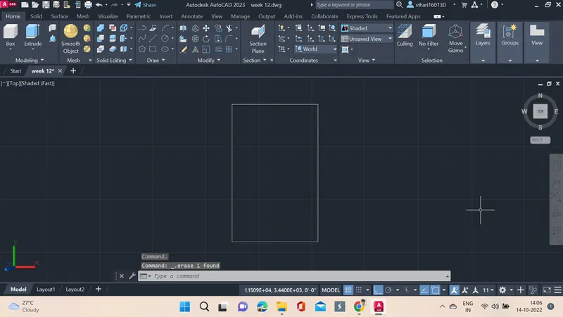
6. O command is used and 9" line is drawn as per the plan.
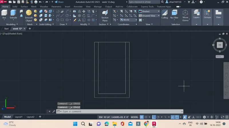
7. Now a window is created as per the plan dimensions are as follow 3'x9".
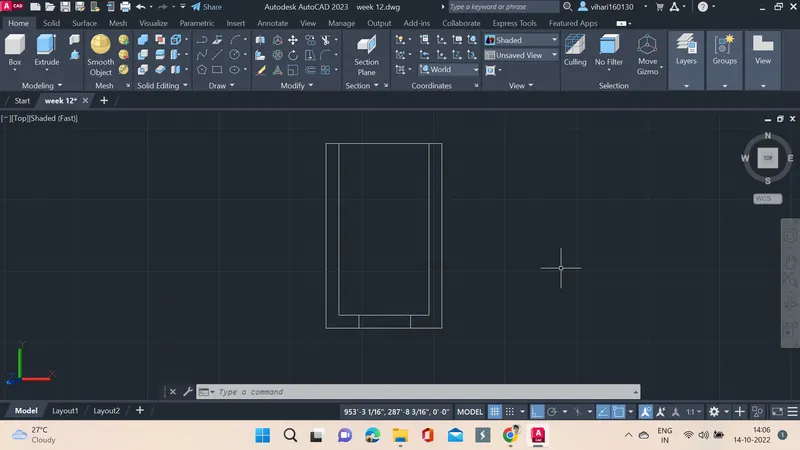
8. H command is used to hatch and dimensions are specified using DIMLIN.

9. Southwest direction is clicked and boundary is specified and selected boundaries.
10. Extrude is used and the points are selected and height is specified as 10'.
11. Visual styles command is used and then shaded is selected.
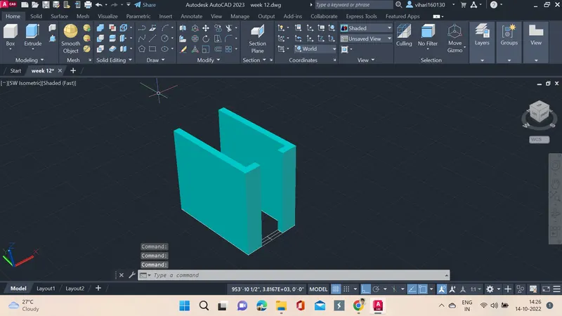
12. Using Rec command the windows are drawn and then the opening is created by erasing the window part.
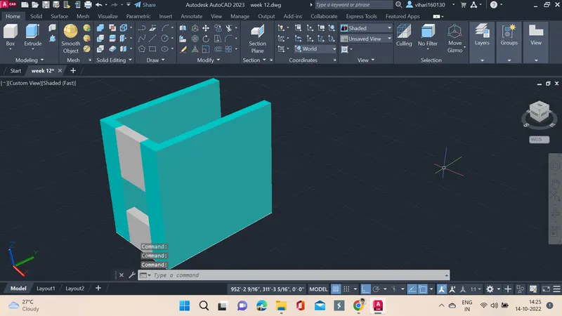
13. The process is repeated to create the elevation.
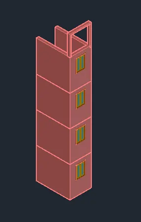
14. Last step is to create window detailing using rec command and dimlin is used to specify the dimensions.
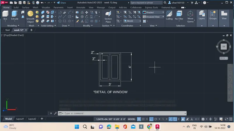
RSEULTS: Using autocad the 3D View of the Building Façade as given in the plan and elevation are created.
AIM: To create the ismoteric 3d view of a stair with railing as shown in the plan and elevation.
INTRODUCTION: Autocad is a software well designed for drawing 2D and 3D plans for the strutcure designs.
PROCEDURE:
1. CAD software is opened and new file is created.
2. UN units command is used to specify the units.
3. From settings 3D modeling is selected.
4. From visual style we select 2D wireframe.
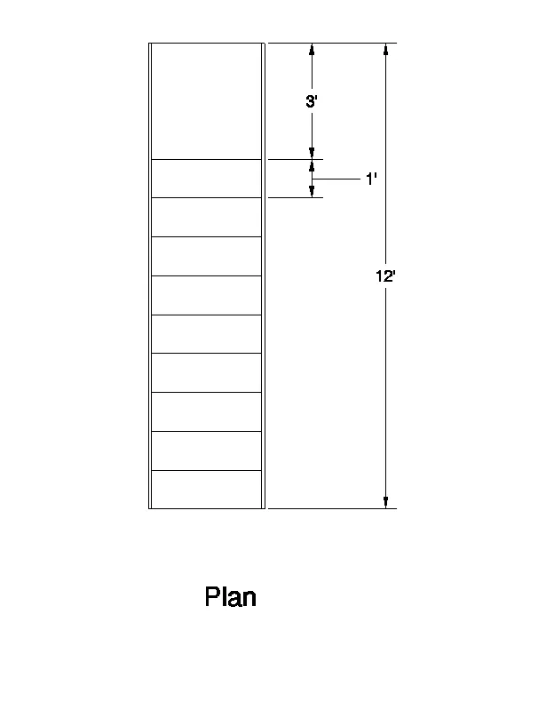
5. REC command is used dimensions are selected and length is specified as 3', width is given as 12'.
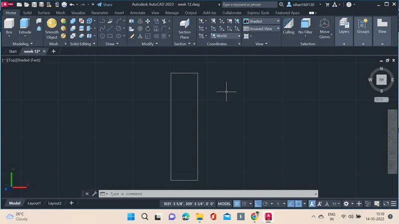
6. O command is used and two lines are drawn at each side, line is drawn as per the fgure at 3' from top.
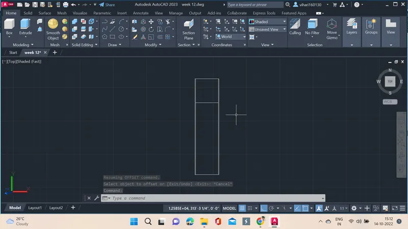
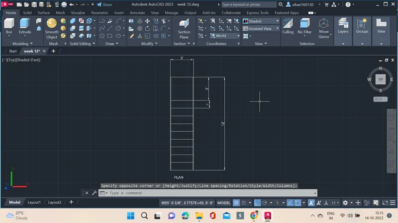
7. O command is used and then steps are drawn at 1' distancefrom top to bottom.
8. DIMLIN command is used to give the dimensions.
9. MTEXT command is used to write the plan.
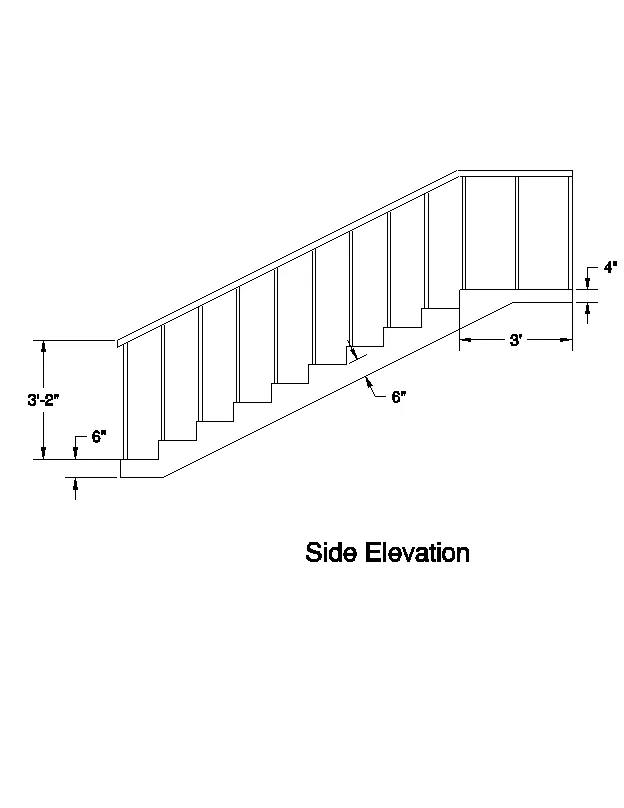
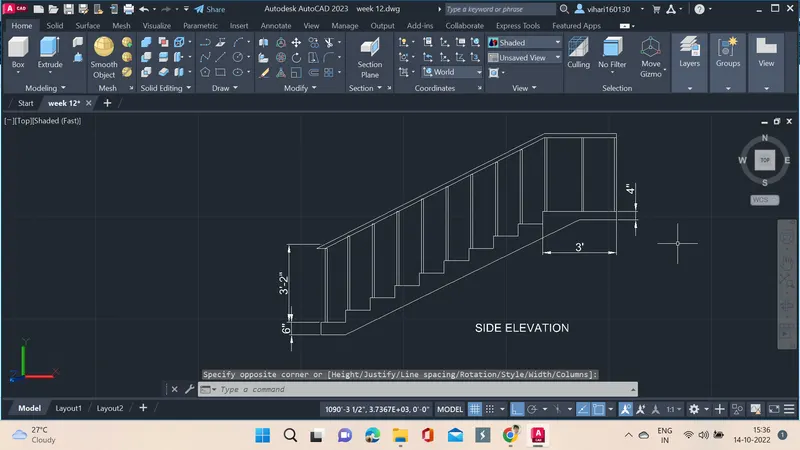
10. Using the Line command side elevation is created.
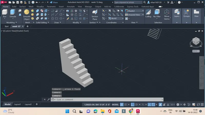
11. The 3D view is created using the southwest direction.
12. Visual styles command is used and then shaded is selected.
13. According to the dimensions the steps are created.
14. Same process is used to created the stairs with railings.
15. C command is used and with radius 0.75" a circle is drawn.
16. Another circle is drawn using radius 0.4" a circl is drawn.
17. The circle of 0.4" os extruded at a height of 3'2".
18. Cylindrical tube is created of this railings.
19. A circle of diameter 2" is drawn on top of the first hand rail.
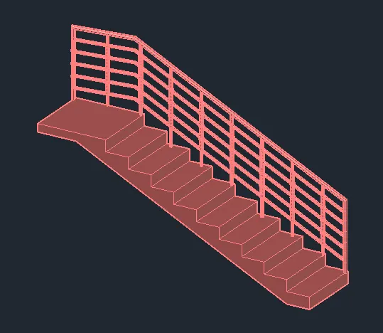
RESULTS: Using autocad the ismoteric 3d view of a stair with railing as shown in the plan and elevation are created.
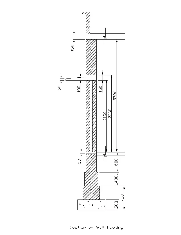
AIM: To create the 3D view of a Wall with spread footing .

INTRODUCTION: Autocad is a software well designed for drawing 2D and 3D plans for the strutcure designs.
PROCEDURE:
1. Autocad software is opened and a new file is created.
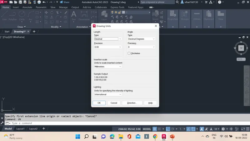
2. UN command is used to set the units to decimal.
3. From settings 3D modeling is selected.
4. From visual style we select 2D wireframe.
5. Using the L command the plan and sections are drawn as per the figure.
6. H command is used to hatch the places as pere the fig.
7. In the next step DIMSTY is used to specify the measures as decimal.
8. DIMLIN is used and the dimensions are specified.
9. MTEXT command is used to write all the required texts.
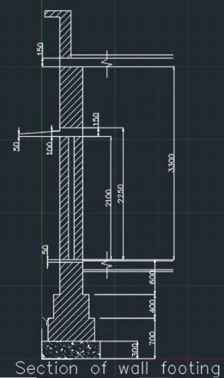
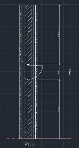
10. The 3D view is created using the southwest direction.
11. Visual styles command is used and then shaded is selected.
12. According to the dimensions the steps are created.
13. Boundary command is to specify the boundary of the section.
14. Click on the extrude option from from the home tab and object is selected to extrude.
15. The height is specified so that extrude can be done.
16. Wall opening is created as per the view.
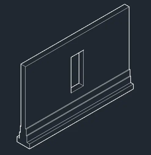
RESULTS: Using autocad the 3D view of a Wall with spread footing is created.