Creating 3D Isometric view of various structural elements in AutoCAD
1) AIM: To create a 3D Isometric View of the building with plan and elevation given.
PROCEDURE :-
- open autocad and change the setting to 3D modelling mode. make sure the units are in inches
- make a layer and name it walls, window plan, window frame, window mullion, window glass, plinth and terrace. assign different colours for each layer.
- convert all units into inches
- take the 2d wiremesh view and take the plan option and draw the plan of the drawing as mentioned in the question using ortho mode and line option
- offset the lines by 9 inch to make the walls
- make the current layer as 'plinth' and using region option make the walls including the windows as a region
- take extrude option and extrude this layer by 4 inch
- now make current layer as 'walls'.enter ucs option and select the face option and click on the top face of the plinth layer.
- copy the plan from the plinth layer and place it on top of the extruded plinth.
- make the regions of the wall a region excluding the windows.
- extrude the walls to a height of 10'.
- now using rectangle option , draw a rectangle over the two windows, make it into a region and extrude to a height of 3'.
- now enter ucs option and then take the face option and place it on top of the extruded walls.
- copy the rectangle of the window on top, make it into a region and extrude it downwards 3'. now we have a hollow section in the place of window. using union option make the walls into a single figure.
- make the current layer as terrace and copy the plan to the top of the wall and make the entire plan into a region.
- now extrude the region by 5" to make the terrace. take the shaded opton to see the 3D view of the building drawn.
- now to draw the windows. go back to the 2d wireframe drawing mode. take the ucs option and place it on the face of the wall where the windows should be.
- there are two types of windows with different sizes. first the wall showing section BB is taken. draw a rectangle outside the surface of size 38" and height 4'. offset the sides by 3" and 4". trim off the unwanted lines to make 3 concentric rectangles. mak ethe current layer as window frame and select the outer recatngle to make a region. then make the current layer as window mullion and make the inside rectangle as another region.
- now make the current layer as window frame and substract the inner region from the outer region.
- make the current layer into window mullion and select boundary option to make the boundary of the inner recatngle . now using region option make it into a region. make the current layer into window glass and then make it into a region.making the current layer as window mullion , substract the window glass region from the window mullion region.
- now making the current layer as window glass, make it into a region.
- draw a handle in another layer with anither colour and repeat the same substraction process.
- check if all the substraction is done correctly by going into the shaded option.
- extrude the window frame by 4", window mullion by 3" and window glass by 2" inwards. now move the window mullion and window glass by 2" inwards and then the window glass by 1" inwards.
- select the whole window and make it into a group by using group option. select the window and move it into the hollow section reserved for the window.
- repeat the same for the window of section AA.
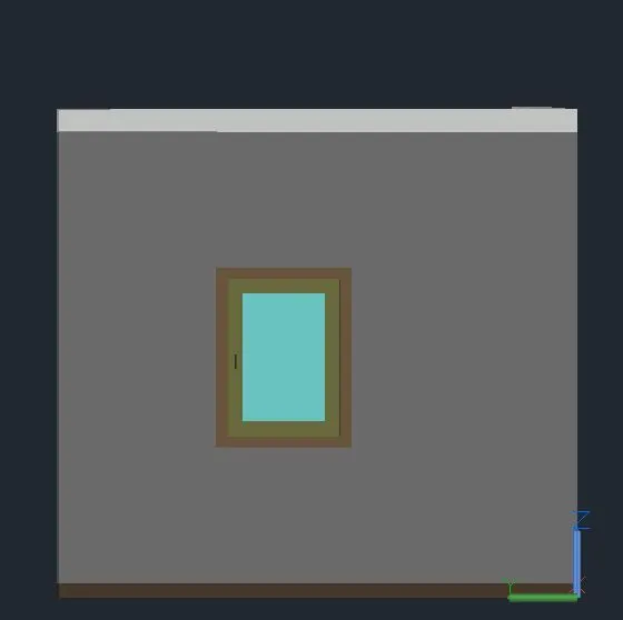
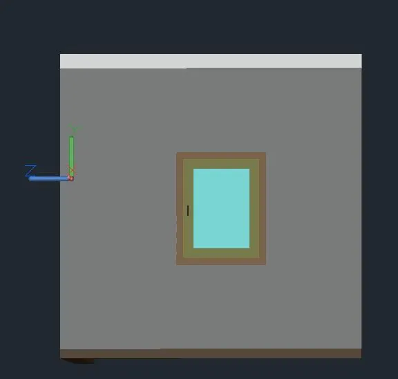
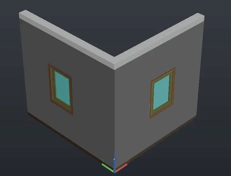
- the resulting figures are shown below ie.:- section A-A, section B-B and the 3D drawing respectively.
2) AIM: To create the 3D View of the Building Façade as given in the plan and elevation
PROCEDURE :-
- open autocad and change the setting to 3D modelling mode. make sure the units are in inches
- make a layer and name it walls, window plan, window frame, window mullion, window glass. assign different colours for each layer.
- convert all units into inches
- take the 2d wiremesh view and take the plan option and draw the plan of the drawing as mentioned in the question using ortho mode and line option
- offset the lines by 9 inch to make the walls
- make the current layer as walls and using region option make the walls excluding the windows as a region
- take extrude option and extrude to a height of 490".
- enter ucs option and select the face option and click on the top face of window in the plan .
- now using rectangle option , draw a rectangle over the two windows, make it into a region and extrude to a height of 54".
- copy the rectangle of the window to heights a s mentioned in the question., make it into a region and extrude it downwards and upwards as required so that we have hollow sections for the windows as shown in fig.1 below.
- using union option make it into a single figure.
- now take the ucs and place it on the face of the wall and draw a recatngle on the top of the building, offset it by 9" inwards and then mak eit into a region and extrude it by 4" towards th einside of the building.
- take the shaded opton to see the 3D view of the building drawn.
- now to draw the windows. go back to the 2d wireframe drawing mode. take the ucs option and place it on the face of the building wall where the windows should be.
- there are two types of windows with different sizes. draw a rectangle outside the surface of size 3' and height 50". offset the sides by 2" and 3". trim off the unwanted lines to make the required window as shown in the window detailing. make the current layer as window frame and select the outer recatngle to make a region. then make the current layer as window mullion and make the inside rectangle as another region.
- now make the current layer as window frame and substract the inner region from the outer region.
- make the current layer into window mullion and select boundary option to make the boundary of the inner recatngle . now using region option make it into a region. mak ethe current layer into window glass and then make it into a region.making the current layer as window mullion , substract the window glass region from the window mullion region.
- now making the current layer as window glass, make it into a region.
- draw a handle in another layer with anither colour and repeat the same substraction process.
- check if all the substraction is done correctly by going into the shaded option.
- extrude the window frame by 4", window mullion by 3" and window glass by 2" inwards. now move the window mullion and window glass by 2" inwards and then the window glass by 1" inwards.
- select the whole window and make it into a group by using group option. select the window and move it into the hollow section reserved for the window.
- repeat the same for the other window type.
- the resulting figures are shown below .
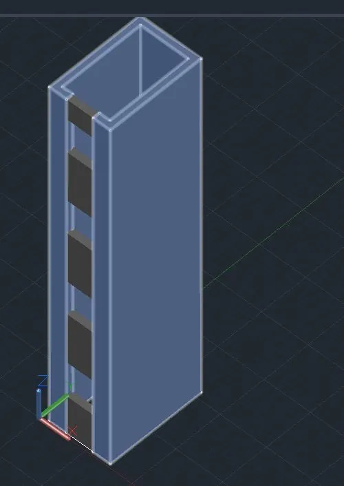
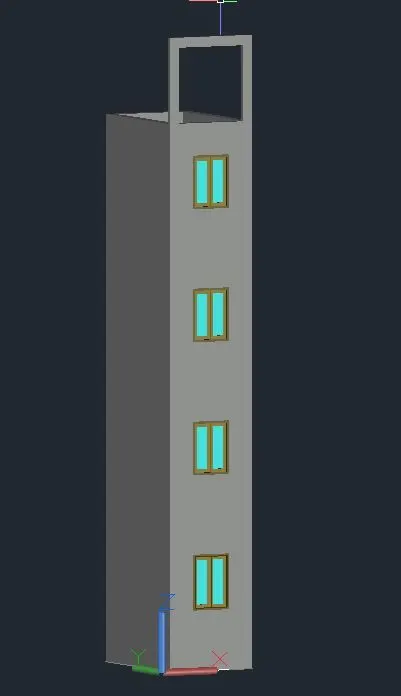
fig.1 fig.2
3) AIM :- To create the ismoteric 3d view of a stair with railing as shown in the plan and elevation. Assume the size of the balustrades and the hand rails.
PROCEDURE:-
- open autocad and change the setting to 3D modelling mode. make sure the units are in inches
- make a layer and name it steps and ballister. assign different colours for each layer.
- convert all units into inches
- take the 2D wiremesh view and take the front option, ie. X-Z plain. to draw the steps using ortho mode and line option.
- draw one rise and thread and then copy the other ten steps using copy paste option. draw the waist slab and join the whole drawing according to the specification given in the question.
- now make a region of the closed surface and extrude the whole drawing in the Y axis.
- now to make the ballisters. make the current layer as ballisters. take the plan view and keep the ucs on the fac eof the first step. using circle option , draw a circle on corner of the first step.
- make the circle into a region and extrude them to the height mentioned.
- now place the ucs on th eface of the second step and copy the ballister to the second step. similartly do the sam efor all the steps by placing the ucs on each step.
- mak ethe ucs as world ucs and then draw the hand rail over the ballisters.
- making the ucs in the YZ plain, draw a rectangle at the end of the hand rail. make it into a region and then extrude it along the path of the handrail. for that select extrude, select the reactnagle , then select the path option and then select the handrail drawn.
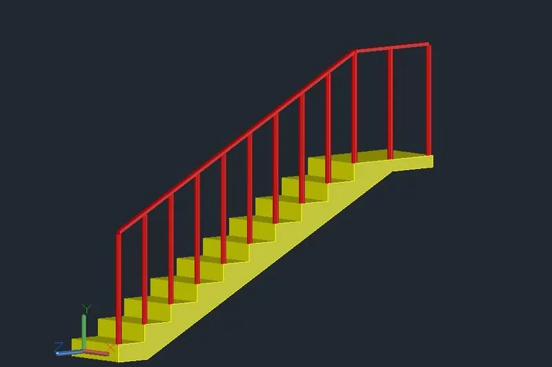
- the final figure is as shown below.
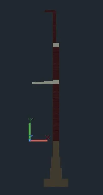
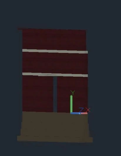
4) AIM :- To create the 3D view of a Wall with spread footing assuming the size of the parpaet and the coping. Create a rendered view of the model with materials as of your choice.. Create the Door opening only.
PROCEDURE:-
- open autocad and change the setting to 3D modelling mode. make sure the units are in mm
- make a layer and name it brick walls, foundation, sunshade, concrete. assign different colours for each layer.
- first take the plan view and draw the plan of the given question.
- take the 2D wiremesh view and take the front option, ie. X-Z plain, to draw the elevation of the wall with the spread footing.
- draw 4 recatngles in the given measurements for the foundation and then draw the walls , lintel layer , sunshade and the parapet .
- move and paste the elevation alligning the plan
- using boundary option make the boundaries and then make a region of the closed surface using region command.make sure each of the drawings are in theor respective layers.
- now extrude all the layers upto the end except the brick from ground till lintel and the sunshade. while extruding this layer, first extrude upto 3300mm and then leave space for the door. since the length before an dafter the door are same we can copy the brick wall.
- move the sunshade and palce it 50mm away from the top of the hollow portion left for the door and then extrude 1000mm.
- now to give material propertries, go to visualize option and select material materials browser. select the category of the required material by clicking on the autodesk library.
- first select masonry . select masonry brick and click on 'add to document'. now select the bricks where masonry brcik is required and right click on masonry brick option and click on 'assign to selection'.
- similarly do the same for concrete and foundation.
- using union option make the foundation layers as one .
- to see the rendered materials, go to realostic option.
- the final figure is as shown below.