Creating 3D Isometric view of various structural elements in AutoCAD
1.
AIM:- To Create a 3D Isometric View of the building with plan and elevation given.
PROCEDURE:-
- Draw the given plan with the help of line tool in the top view (X-Y plane)
- Now convert the lines into region by selecting the respective lines to be converted into region.
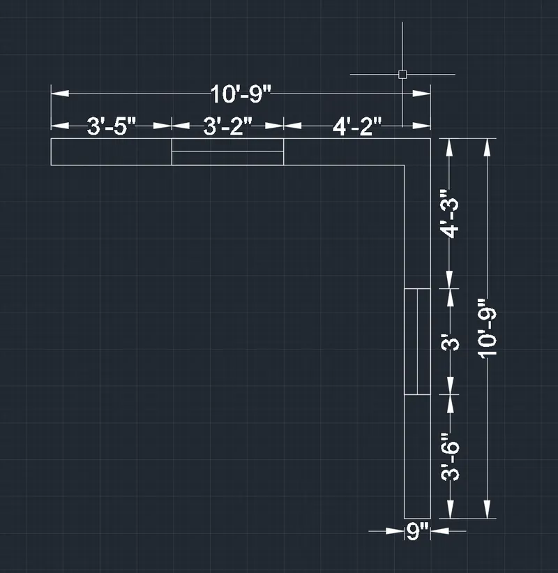
- Now select the region for wall and then enter the command extrution.
- Now extrude the wall upto 10' height.
- Now select the region for window and then extrude it upto the height of 4'.
- Now move the extrurion of window upto the height of 3'.
- Now enter command "Substract" and then select wall first and then press enter and then select the window so the window will be substracted from the wall.
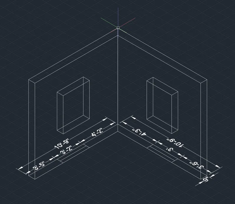
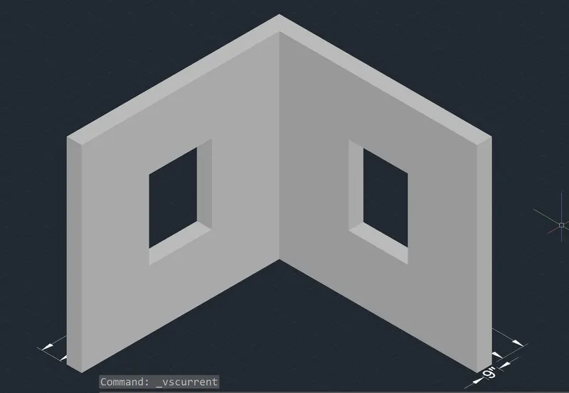
- Now for the window select the region for the windows and copy it beside the drawing and then decrease the width from 9" to 7" to provide a window frame.
- Now select the region and extrude the window frame upto the height of 4'.
- Now put the rectangle at the bottom of length 3" shorter from both the sides to give the thickness of the frame.
- Now extrude the rectangle upto the height of 3'6".
- Now move the extrution upto the height of 3" to create a perfect frame for the window.
- Now draw a rectangle of the length as same to the width of the open surface of the window frame.
- Now decrease the width of the rectangle upto 2" and the extrude the rectangle upto the height of the 3'6".
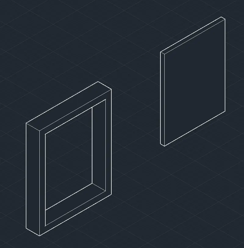
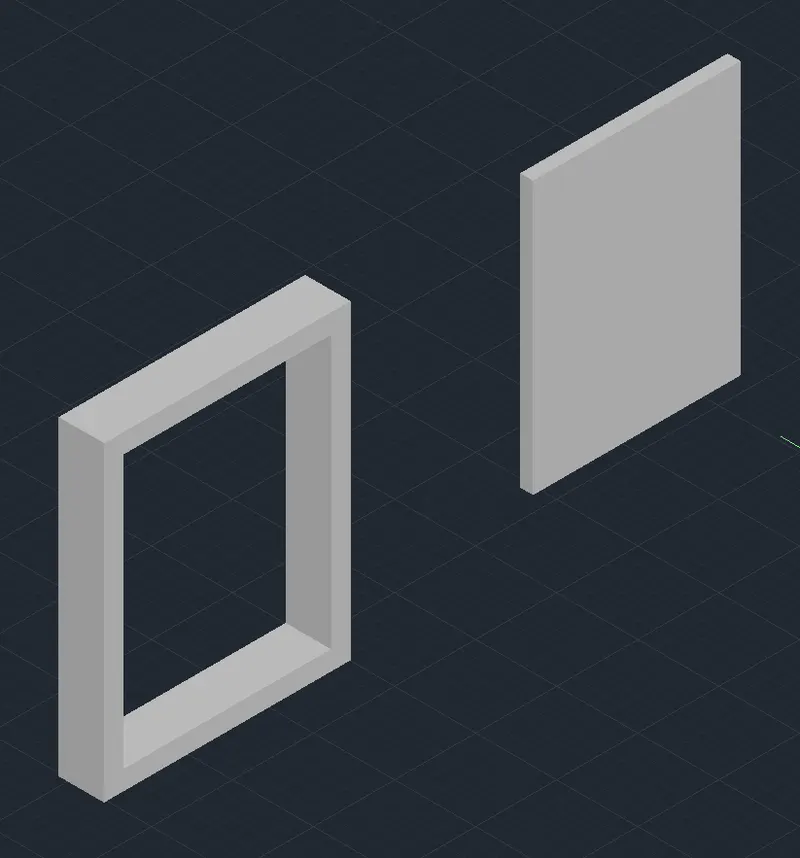
- Now move the 2" wide extrution into the window frame to make it like a window structure.
- Now add the materials to the whole window like glass and wood to make it look like a window.
- Material is to be added from the "VIEW > MATERIAL BROWSER"
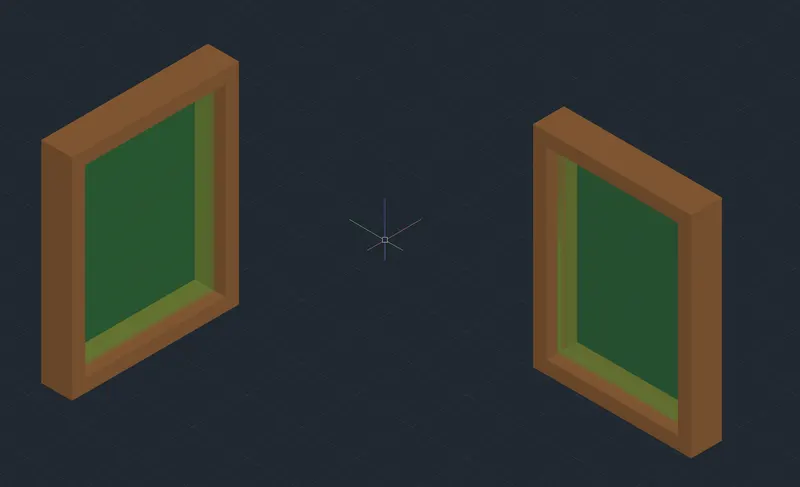
- Now move this windows into the wall extrution to complete the drawing.
- And also add the concrete material to the wall to make it look realistic.
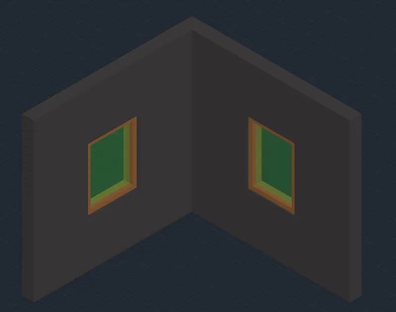
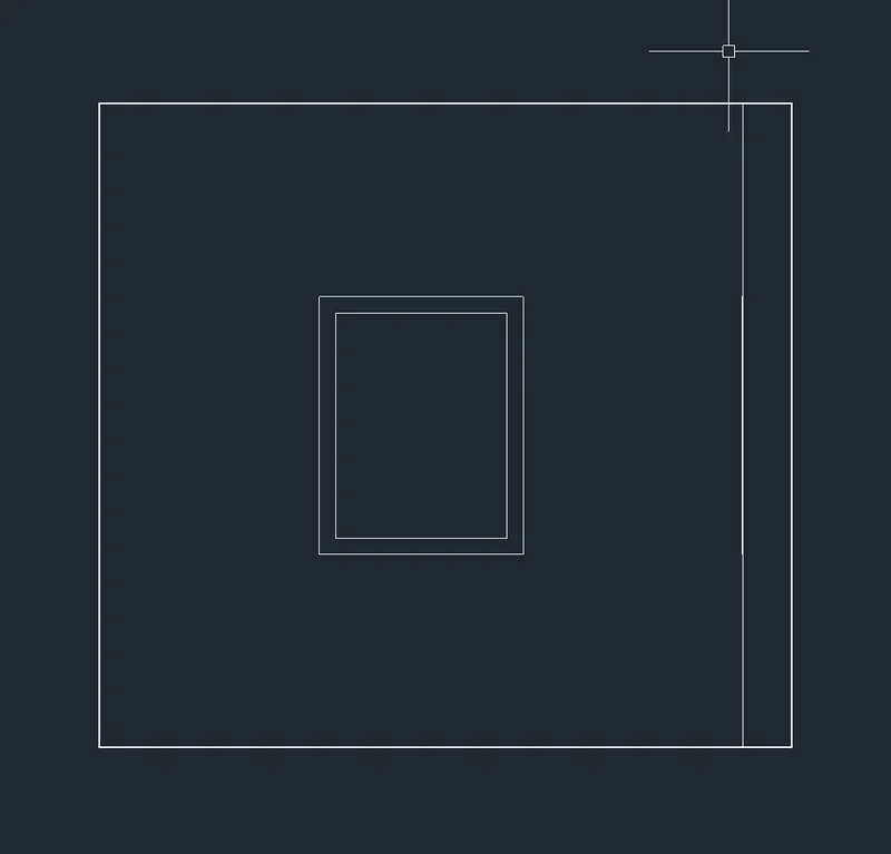
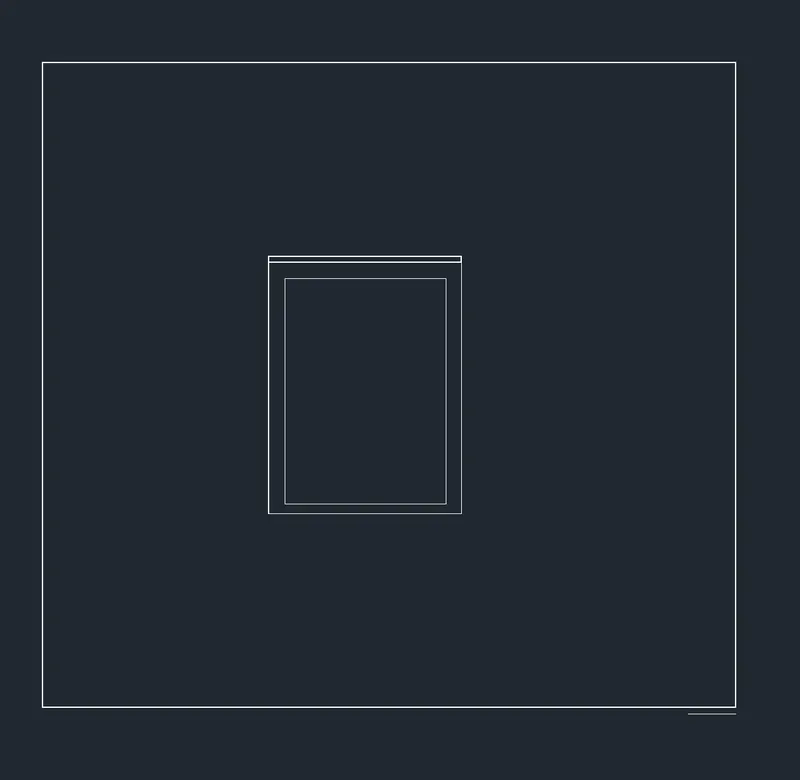
- Now for both the elevation views first move the view cube to front and then right for the second elevation.
--------------------------------------------------------------------------------------------------------------------------------------
2.
AIM:- Create the 3D View of the Building Façade as given in the plan and elevation. Also, see the detail of the window.
PROCEDURE:-
- Draw the given plan with the help of line tool in the top view (X-Y plane)
- Now convert the lines into region by selecting the respective lines to be converted into region.
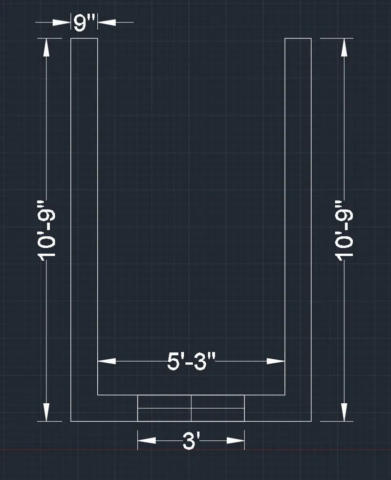
- Now select the region for wall and then enter the command extrution.
- Now extrude the wall upto 10' height.
- Now select the region for window and then extrude it upto the height of 4'.
- Now move the extrurion of window upto the height of 3'.
- Now enter command "Substract" and then select wall first and then press enter and then select the window so the window will be substracted from the wall.
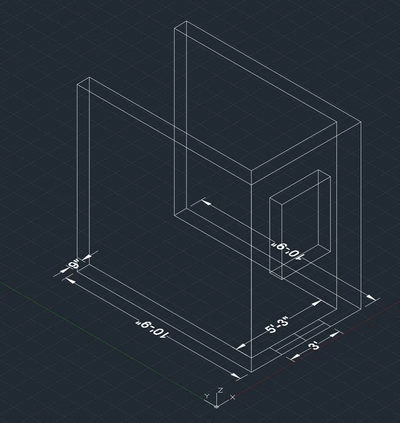
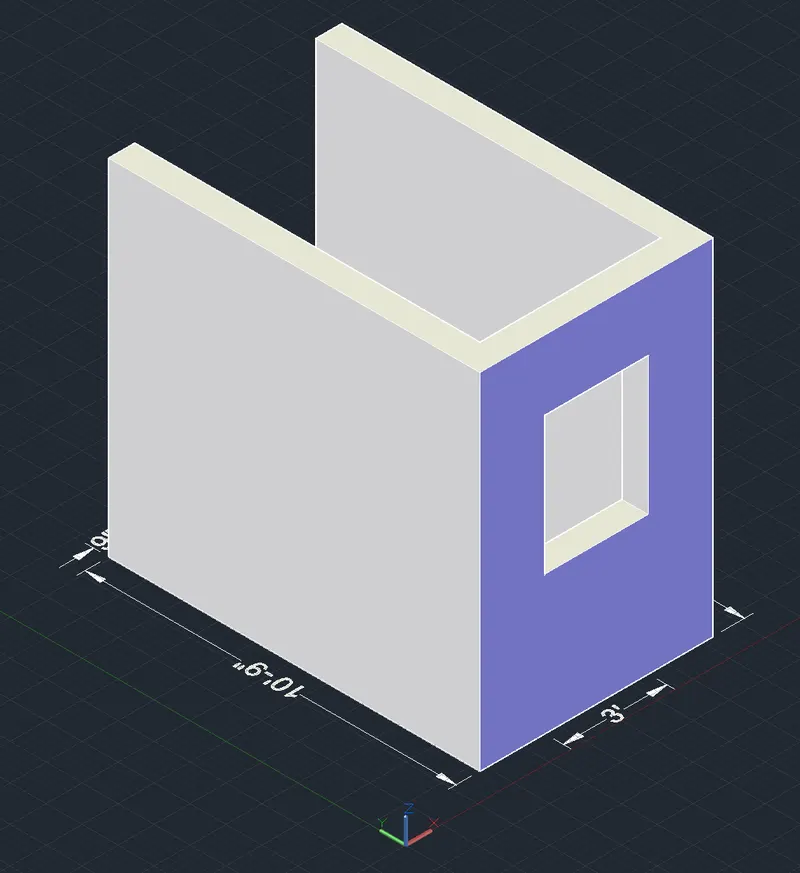
- Now for the window select the region for the windows and copy it beside the drawing and then decrease the width from 9" to 7" to provide a window frame.
- Now select the region and extrude the window frame upto the height of 4'.
- Now put the rectangle at the bottom of length 2" shorter from both the sides to give the thickness of the frame.
- Now extrude the rectangle upto the height of 3'8".
- Now move the extrution upto the height of 3" to create a perfect frame for the window.
- Now draw a rectangle of the length as same to the width of the open surface of the window frame.
- Now decrease the width of the rectangle upto 2" and the extrude the rectangle upto the height of the 3'6".
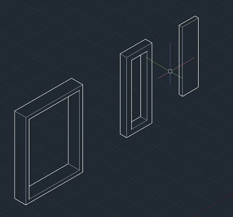
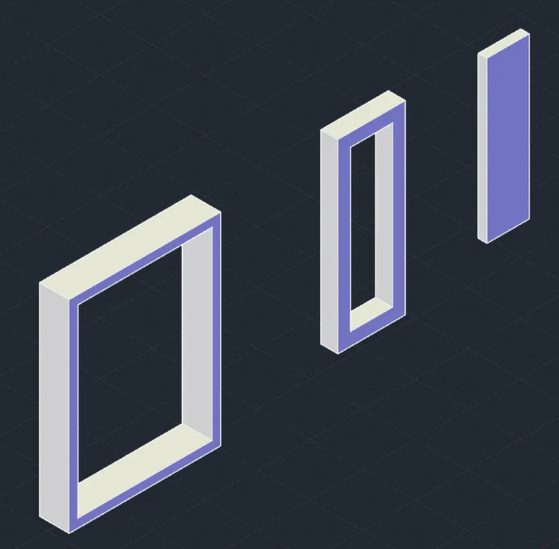
- Now move the 2" wide extrution into the window frame to make it like a window structure.
- Now add the materials to the whole window like glass and wood to make it look like a window.
- Material is to be added from the "VIEW > MATERIAL BROWSER"
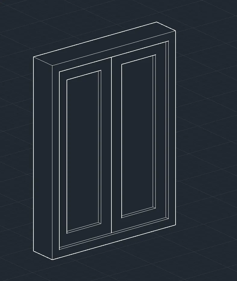
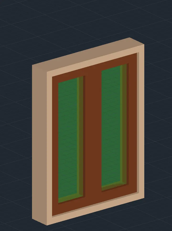
- Now move this windows into the wall extrution to complete the drawing.
- And also add the concrete material to the wall to make it look realistic.
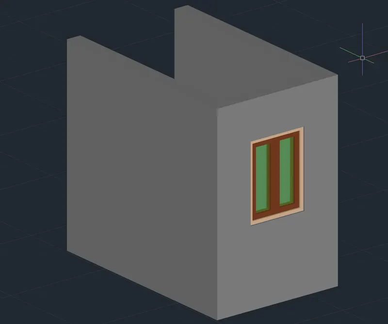
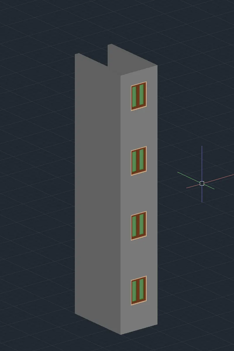
- Now for the floors select the whole drawing and then enter the command copy and then slect the base point as bottom point and copy it 4 times to the top point.
----------------------------------------------------------------------------------------------------------------------------------------
3.
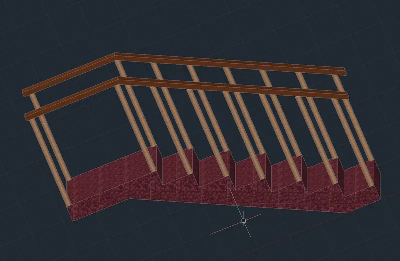
AIM:- Create the ismoteric 3d view of a stair with railing as shown in the plan and elevation. Assume the size of the balustrades and the hand rails.
PROCEDURE:-
- Set the work plane to the left and then start the work.
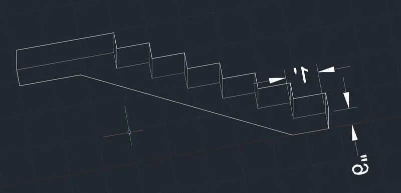
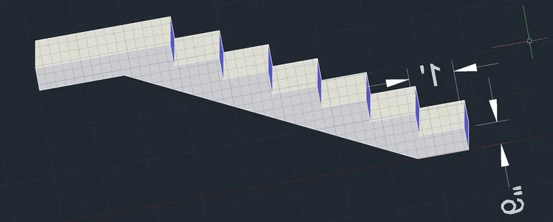
- Now draw a stair case each stair size (riser=6") & (Tread=1') with the help of poly line in a closed shape.
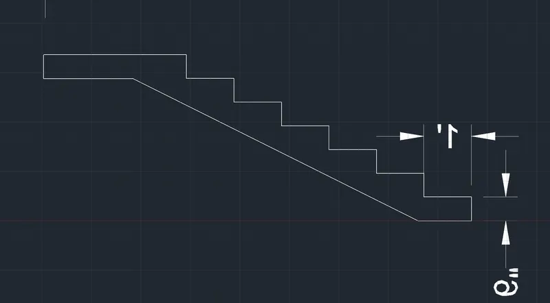
- now select the polyline and then enter the command extrude and enter the width of the extrude as 3'.
- So now 3D model of the stair is created.
- Now move the work plane to the top and then draw a circle and then move it on the first stair and then extrude it up to the height of 3'
- Now copy the same extrution on the other side of the stair and then copy both the end extrutions on all the stairs.
- Now create a line 1" above the circular extrution ending and then draw a rectangle at the start of the line and then extrude that rectangle and give it a path of the drawn line to create a railing.
- The circular extrutions will act as balusters of the railing.
- Now give the respective materials to the different elements.