Creating 3D Isometric view of various structural elements in AutoCAD
CREATING 3D ISOMETRIC VIEW OF VARIOUS STRUCTURAL ELEMENTS
Introduction
Isometric drawings: These drawings are not actual 3D drawings, they are made with 2D geometries but they appear like 3D. Isometric drawing in AutoCAD can be made by tilting viewing angle to 30 degrees for all of its sides in the 2D plane. Isometric drawing can now be easily created using the isodraft option in AutoCAD which enables us to switch between the planes. In AutoCAD, 3D modelling can be used to draw the isometric view of different elements.
Rendering AutoCAD: A realistic rendering of a 3D model give a clearer vision of a conceptual design than a plotted drawing.
Rendering is process of creating a raster image based on 3D objects in a scene. A renderer is used to calculate the appearence of the material attached to the objects in a scene, and how lightings and shadows are calculated based on lights placed in a scene.Environmental and exposure settings of the renderer can be adjustedto control the final rendered image.
The basic rendering workflow is to attach materials to the 3D objects of a model, place user defined lights, add a background and start the renderer with the RENDER command.
1.
Aim:
To create the 3D isometric view of a building with plan and elevation given:
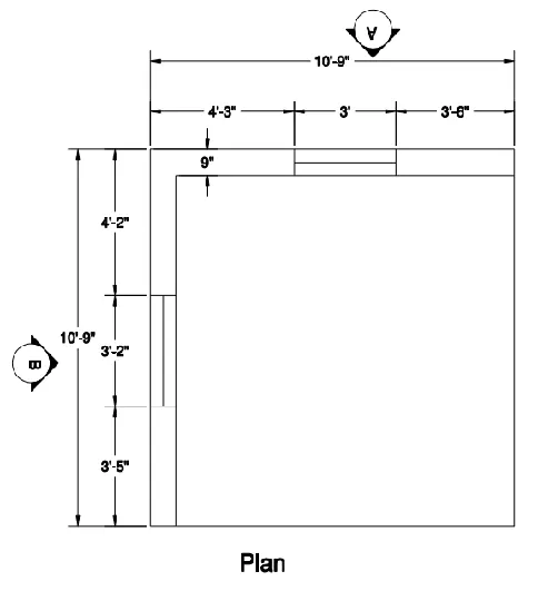
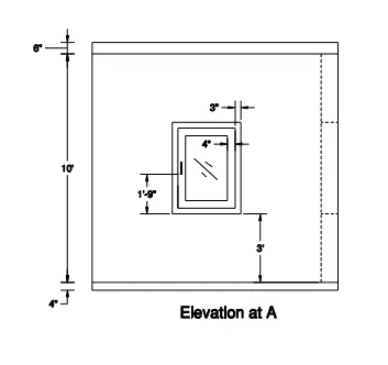
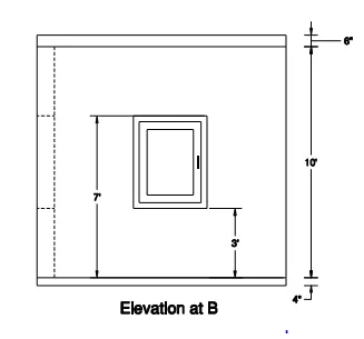
Procedure:
- Initially, open the AutoCAD and go to 3D modelling.
- Then set the units of the drawing as engineering (feet and inches).
- Now set the limits:
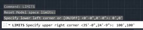
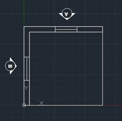
- Now, in the AutoCAD take the top view and intially draw the plan as given in the question.
- Using the line command the top plan is created as below:
- Now, using the dimlin command provide the dimension.
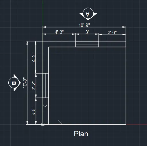
- Now hide the dimension layer.
- Then type BO command to create the boundary region for the walls and then extrude it.
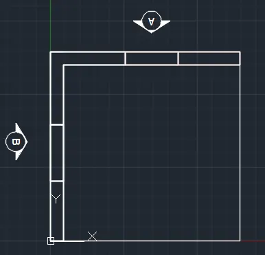
- Now, change the view to south west.
- Create the region and extrude it upwards at an extrusion height of 10'10".
- Using 3D orbit the the view direction.
- Then in the window portion of the plan create a rectangle and convert it into region and extrude it also to create a window in the wall.
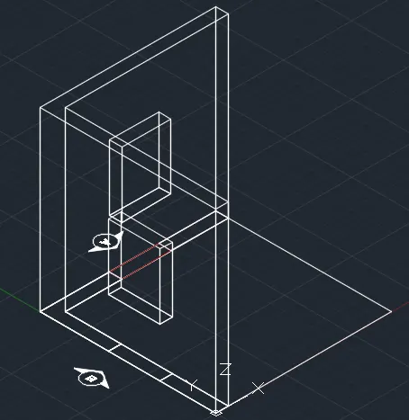
- Now, go to the backview and create the window using the rec command.
- This is elevation A.
- Now provide the dimensions.
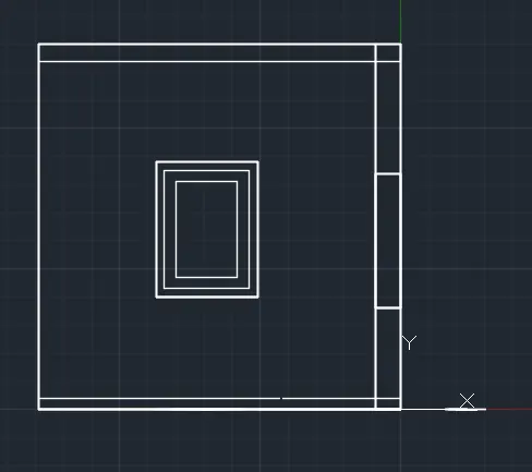
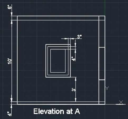
- Now, similarly draw the elevation at B by taking the right view.
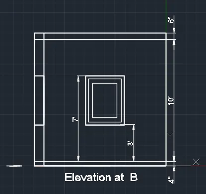
- Now, again go to top and assign layer to the walls.
- Then create the boundary region so thaat it can be extruded to create the 3D wall.
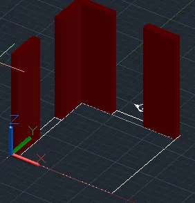
- Now, draw a rectangle at the window portion and create the boundary to it and then copy this rectangle vertically at adistance of 3'4" , 4' and 3'10".
- Then extrude this rectangle to complete the wall.
- Then provide the necessary hatching for the windows and the isometric view is completed.
- Now, the final isometric view is as given below:
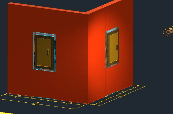
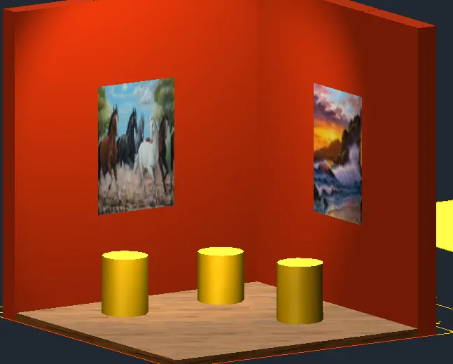
2.
Aim:
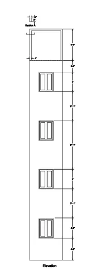
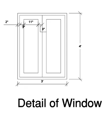
To create the 3D view of the building facade as given in the plan and elevation:
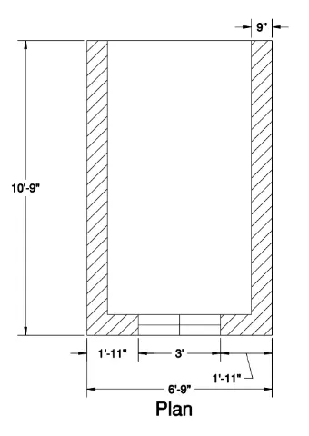
Procedure:
- Initially, open the AutoCAD and go to 3D modelling.
- Then set the units of the drawing as engineering (feet and inches).
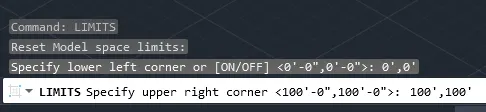
- Now set the limits:
- Now choose the line command and create the plan as gien in the question.
- Now, provide the hatch using the hatch command.
- Now using dimlin command provide the dimensions and using the mtext command provide the texts.
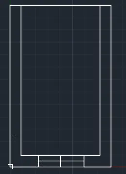
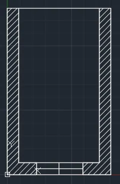
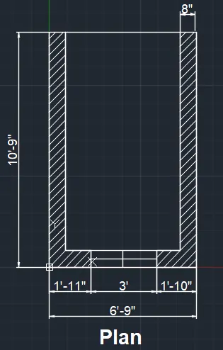
- Now hide the dimensions and texts and hatch to create the isometric view and elevation of the plan.
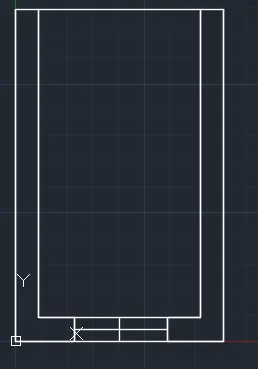
- So for that initially create the boundary region using the boundary command.
- Then extrude it upwards at a height of 40'10".
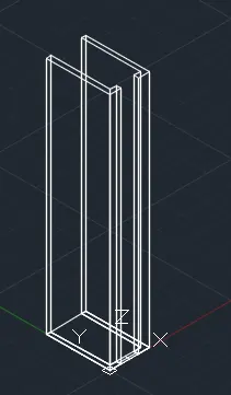
- Now create the windows at its required positions.
- Convert the figure to shaded view.
- Then draw a rectangle at the window position and convert it to a boundary region and then copy it to the window positions.
- Then extrude it to complete the 3D wall.
- Then using union command unite all the different components.
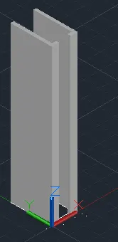
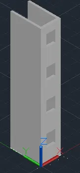
- Now, create the window separately in the right viewand dimension it.
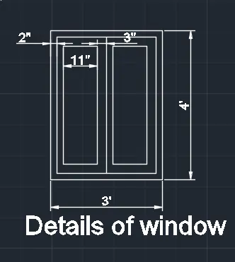
- Now hide the texts and dimensions and continue.
- Then using the command rotate 3D bring that window to the front view.
- Now place these windows in the front view of the structure created.
- Now, provide the dimensions.
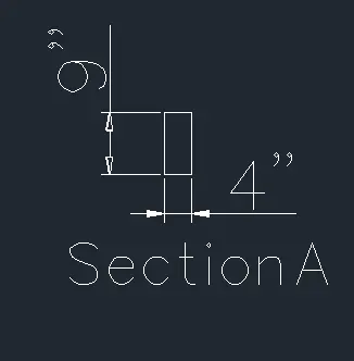
- Section A is also developed.

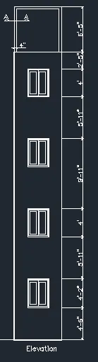
- Now we have to complete the isometric view of the given question.
- For this hide the dimensions and texts and then change to south west view.
- Now assign layers to different components.
- Change the view to shaded.
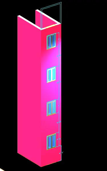
- Hence, the isometric view is created as follows:
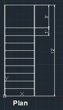
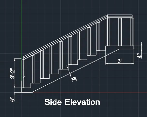
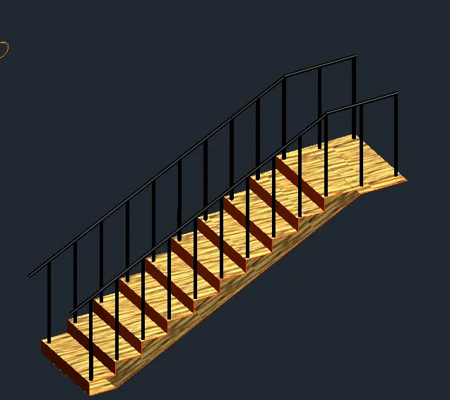
3. Isometric 3D view of a stair with railing as given in plan and elevation is given below:
- Isometric view developed is given below:
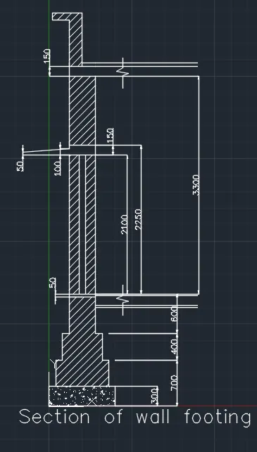
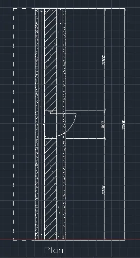
4. 3D View of a wall with spread footing is given below:
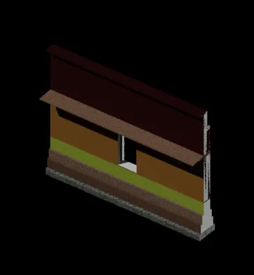
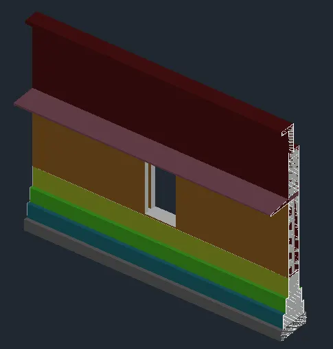
- Isometric view of the wall is :
sometric view of the wall is :
- Rendered image is: