Creating 3D Isometric view of various structural elements in AutoCAD
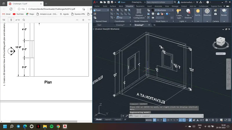
Aim & Intorduction: Creation of a 3D Isometric View of the building with given plan and elevation
Procedure:
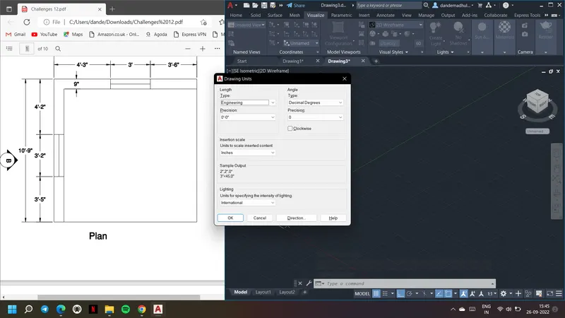
1. First open a new drawing sheet and choose the units as engineering.
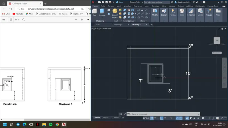
2. Draw the recgangle with given dimensions as shown
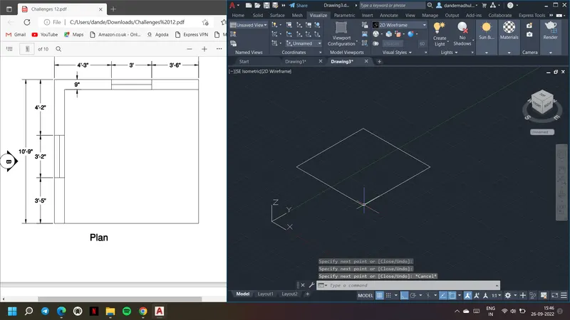
3. Offset the two sides with offset distance 9" using offset command
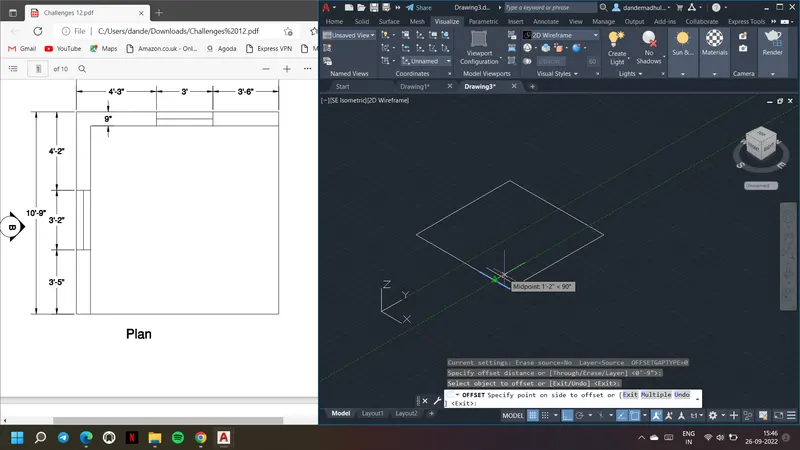
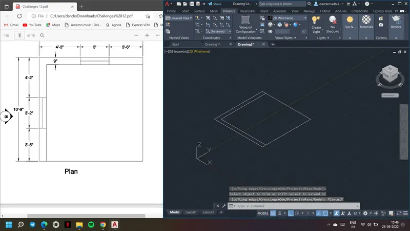
4. Draw two rectamgles as shown to form the region
5. Extrude the two rectangles upto height 10' 10" as per elevation A and elevation B
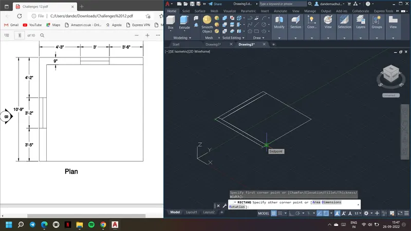
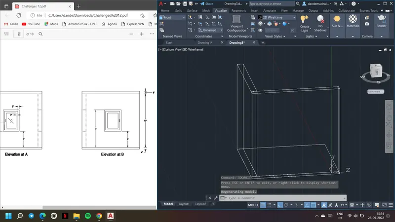
6. For window view draw the lines as shown with 3'2" window length
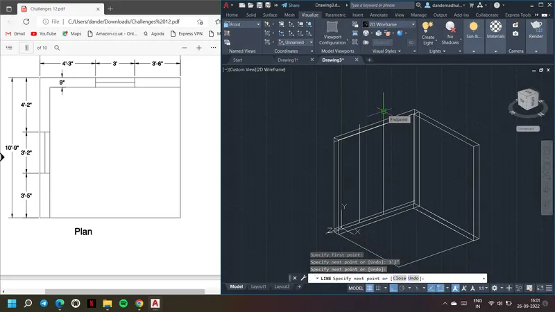
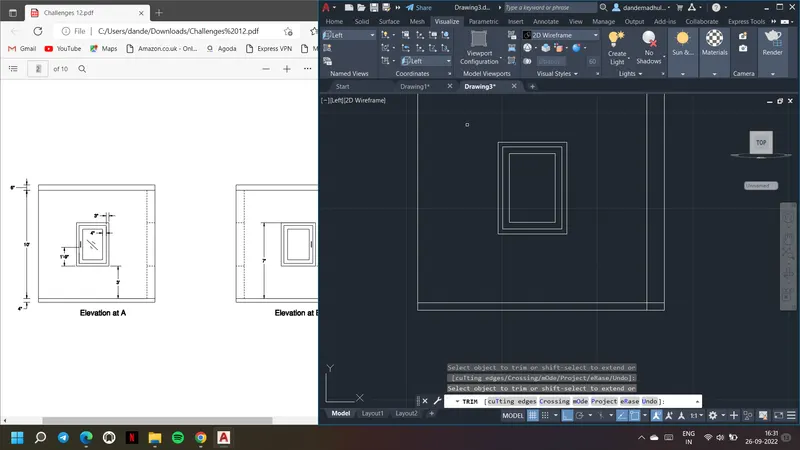
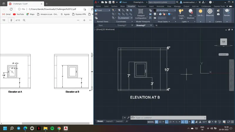
7. Draw the rectangle as per the dimensions given in elevations. Offset the drawn rectangle 3" and 4" respectively
8. Change the views on visualize if required to work on the elevations separately
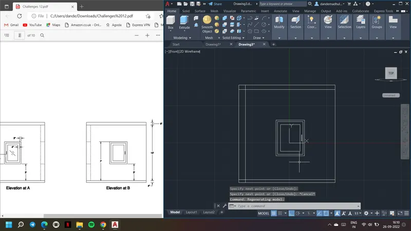
9. Use ucs command and place uce whereever required and using dimlinear insert dimensions
10. Similarly draw elevation A by drawing window and inserting dimensions using ucs
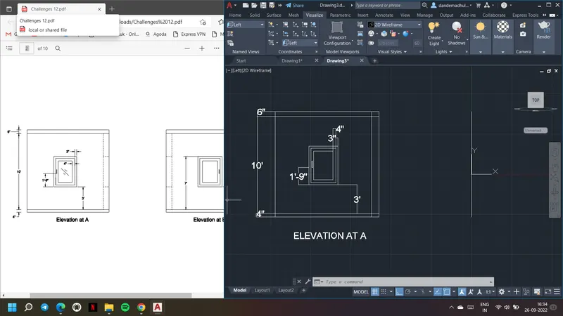
Result: 3D Isometric View of the building with given plan and elevation
Aim & Introduction: Creation of the 3D View of the Building Façade as given in the plan and elevation. Window details is also given.
Procedure:
1. Open the new drawing sheet and choose the units as engineering
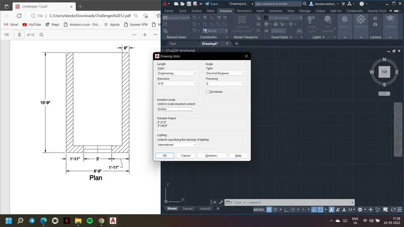
2. Create the rectangle with given dimensions as shown
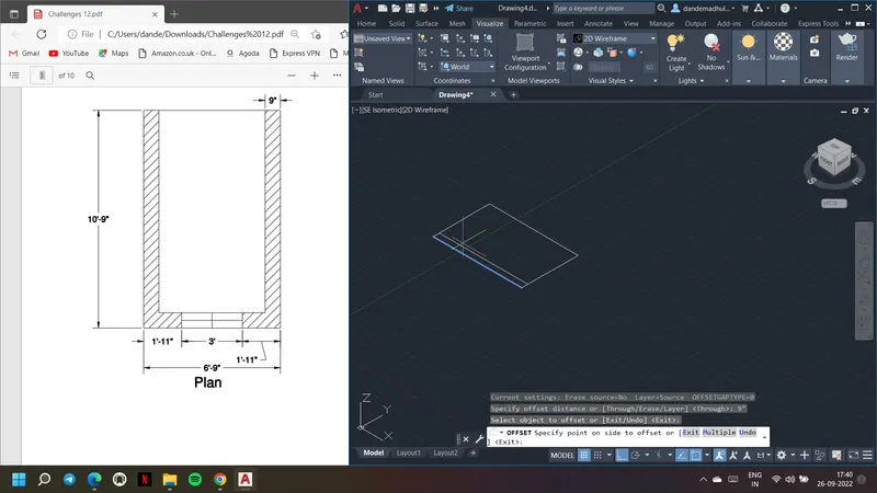
3. Offset the required three sides with offset distance 9" using offset command
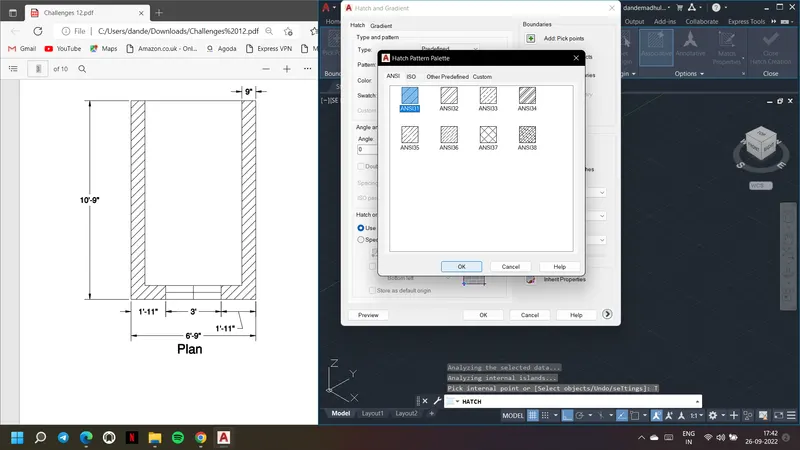
4. Go to hatch command and hacth settings, choose the required hatch pattern and scale
5. Hatch the three regions as shown
6. Using dimlinear insert the dimensions wherever required, use ucs comamnd if needed
7. If required change the color of dimensions and hatch to distinguish them from drawing
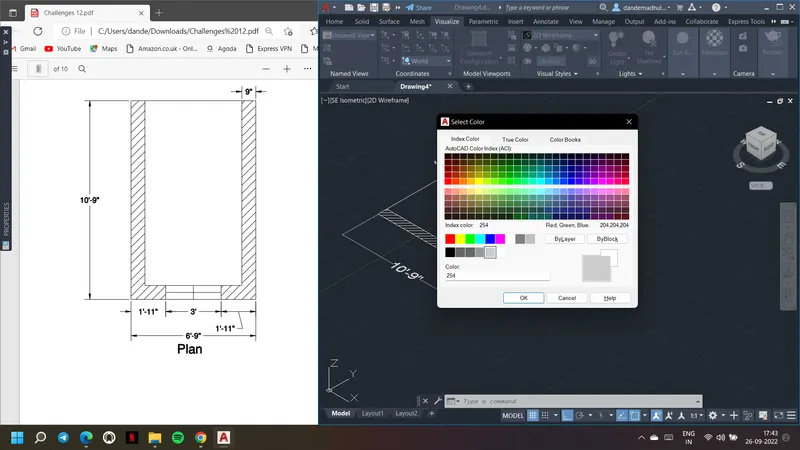
8. required plan is drawn, for 3' window gap is provided and not hatched as shown
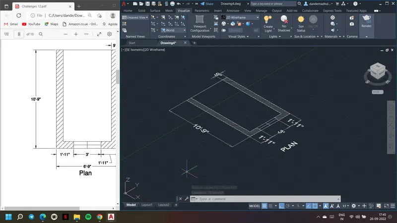
10. Extrude the wall shown using extrude command and height as per the given elevation details
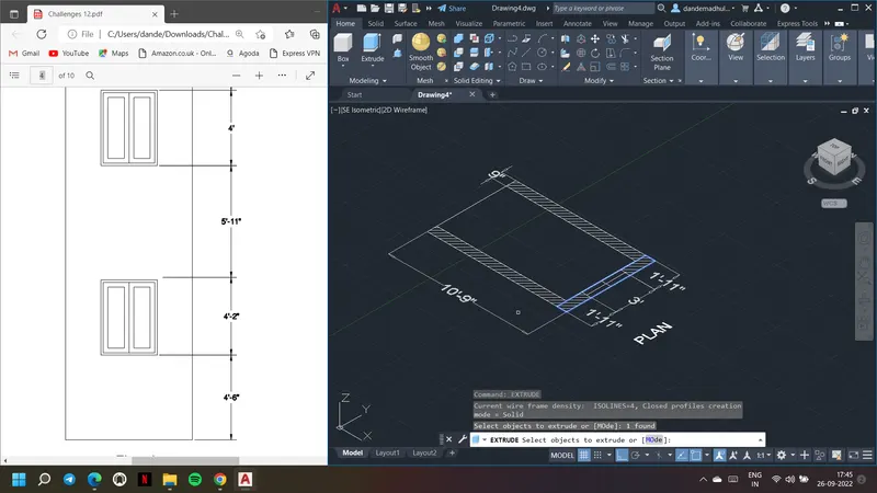
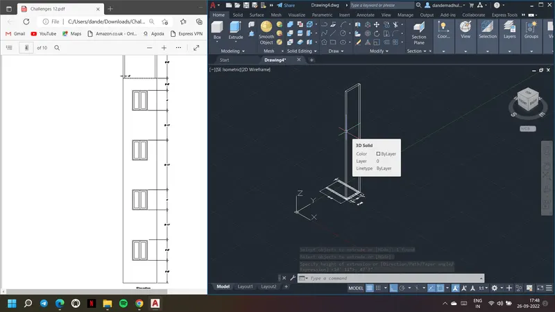
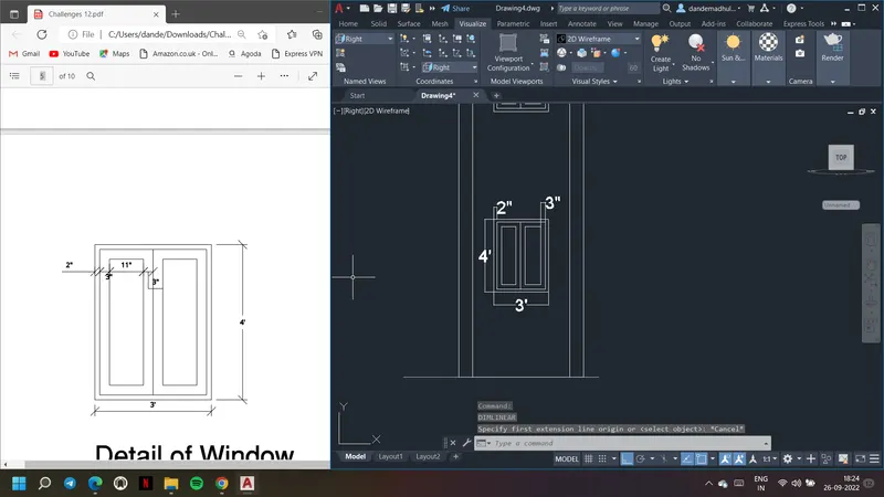
11. Draw the window using dimensions given , using line command and offset command
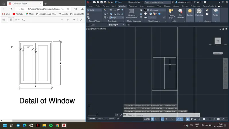
12. After creation of window copy it and paste wherver required as given
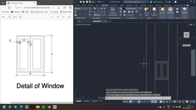
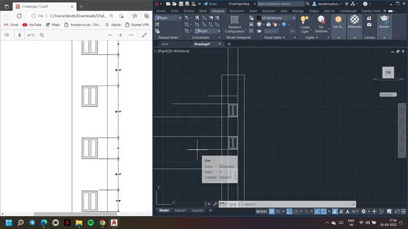
13. Form the top of the building with offset distance 4"
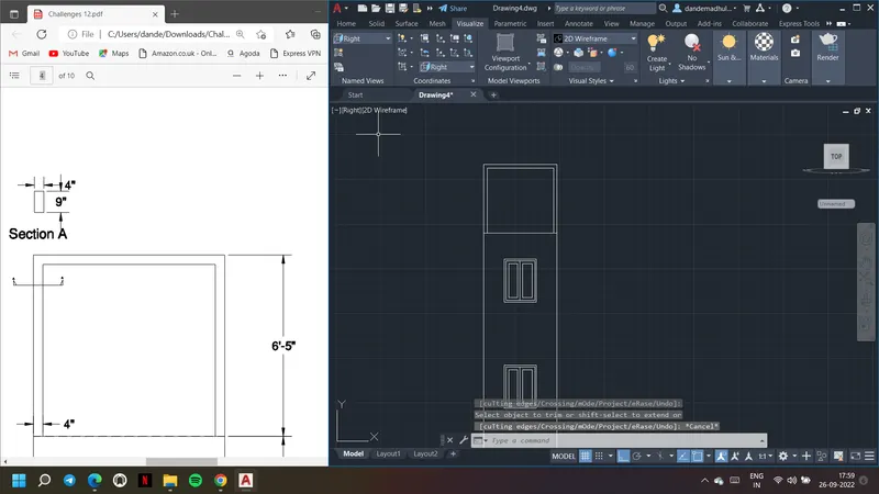
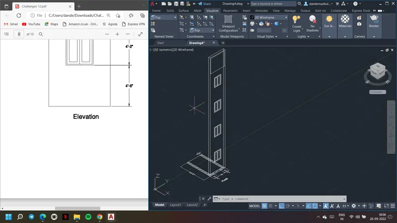
14. Extrude the other two walls of the building using extrude command
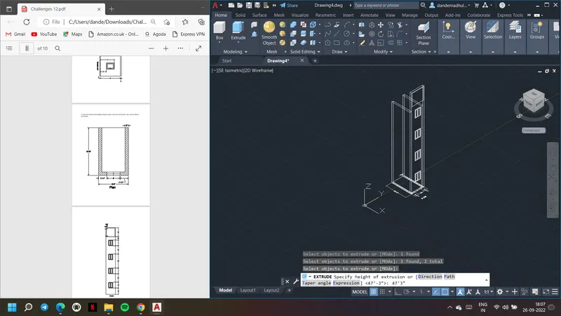
15. Insert dimensions using dimlinear command for window and wall as shown, use ucs command if needed
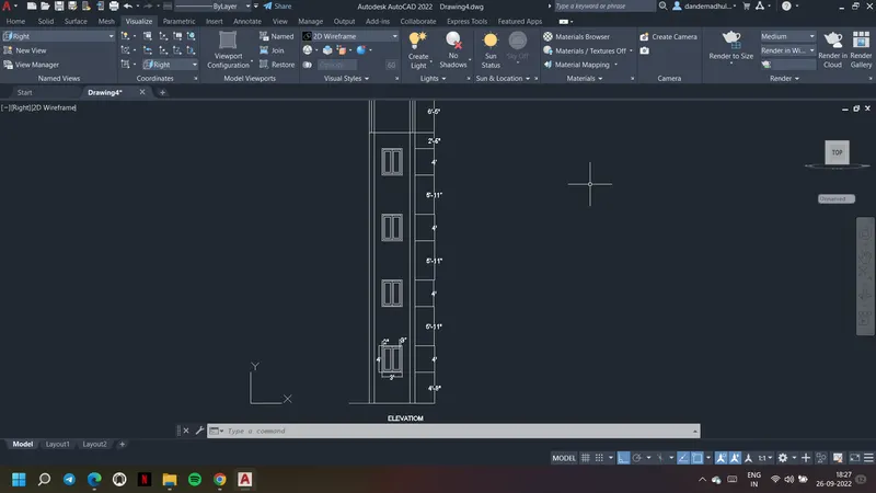
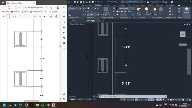
Result: 3D View of the Building Façade as given in the plan and elevation.
Aim & Introduction: Creation of the ismoteric 3d view of a stair with railing as shown in the plan and elevation. The size of the balustrades and the hand rails are assumed.
Procedure:
1. Open the new drawing sheet and set units as engineering
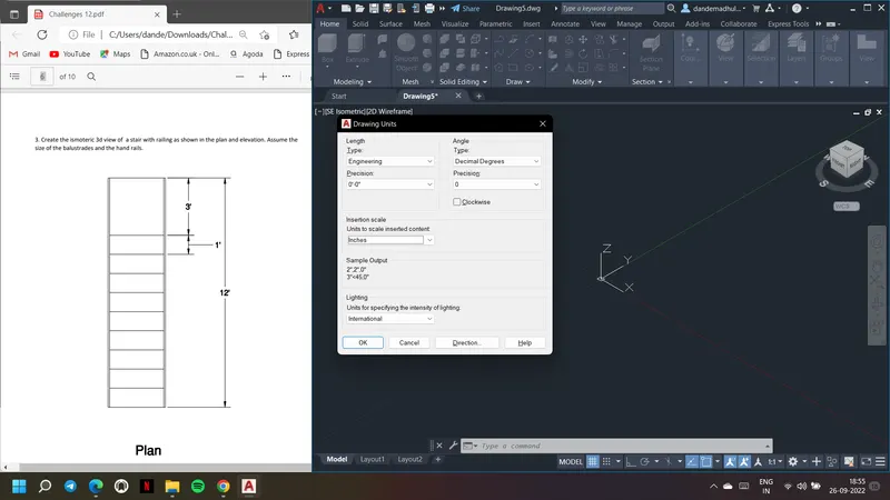
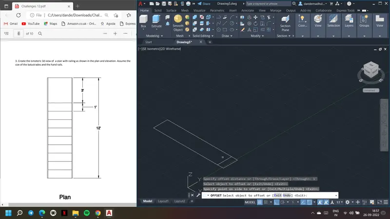
2. First using plan draw the rectangle with given dimensions
3. Using offset command and offset distance as 1' draw the steps as shown
4. Insert the dimensions using dimlinear command, use ucs command if needed
5. Use text command to insert the text in the drawing
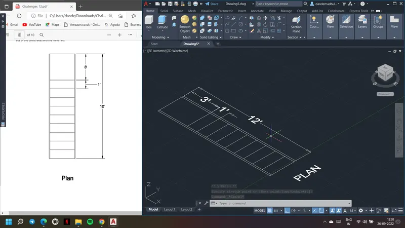
6. Now using line command, rise as 6" and thread as 1', draw the steps as shown
7. Draw the stands similarly using line command, ortho mode. Use mirror command to mirror the drawn items
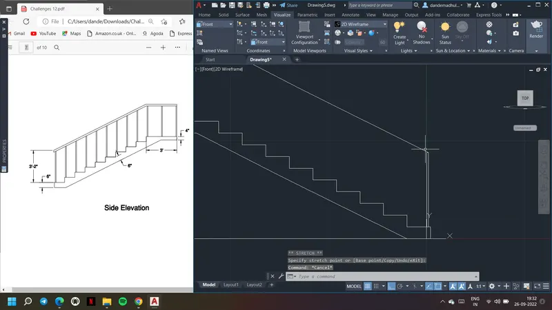
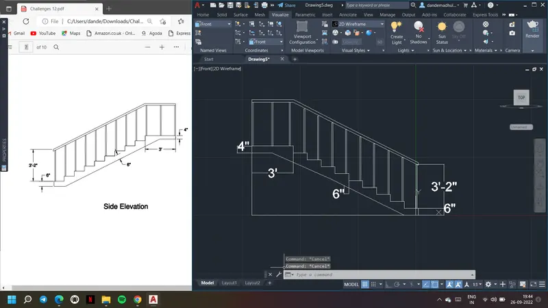
8. Use dimlinear to insert the dimensions, use ucs command to measure the dimensions of the selected drawing
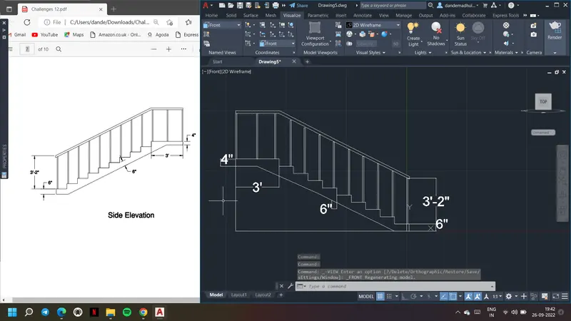
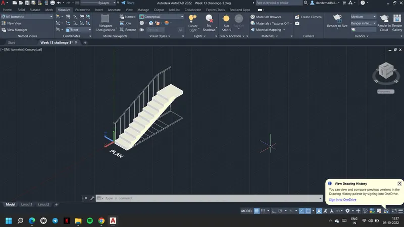
Result: The ismoteric 3d view of a stair with railing
Aim & Introduction: Creation of the 3D view of a Wall with spread footing. The door opening is created as given. The plan and elevation is referred for the details. Rendered view of the model is created and using material browser materials are assigned to the wall.
Procedure:
1. Open the new sheet of drawing and choose the units as decimal
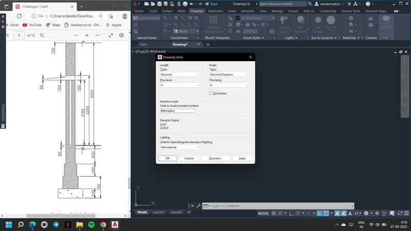
2. Using line command and ortho mode draw the given footing
3. Draw a rectangle with given dimensions and usind lune command draw the remaining part of footing
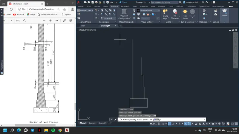
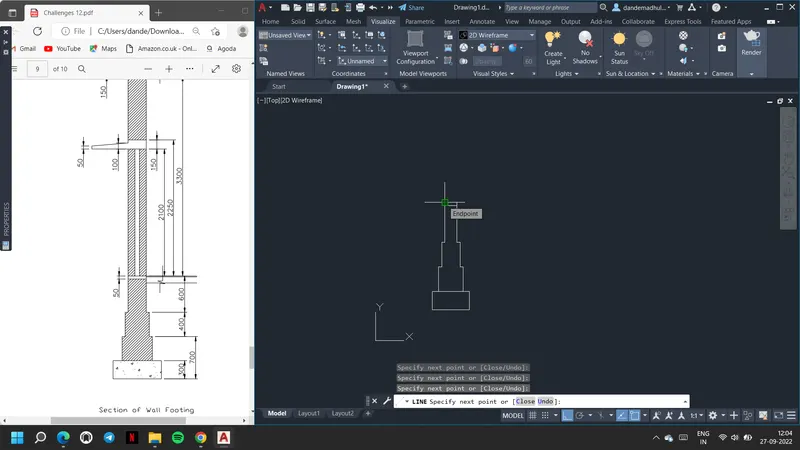
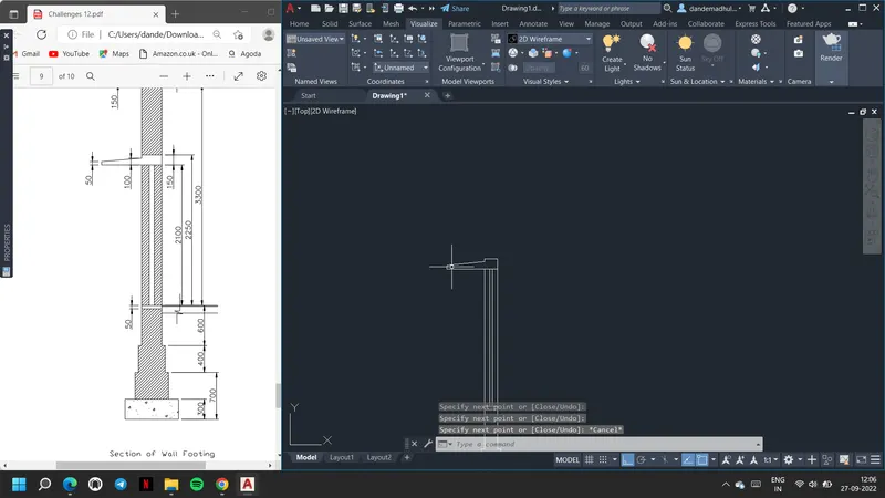
4. Go to hatch command and hatch settings to choose the required hatch pattern. Scale the hatch if required
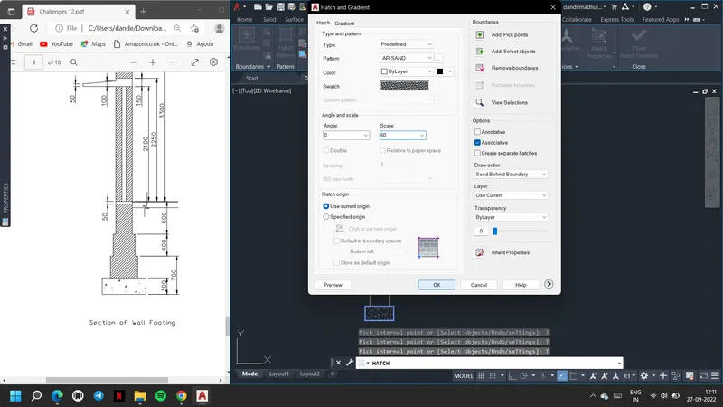
5. Hatch the mentioned portions and insert dimensions using dimlinear command

6. Insert text using dtext command. Change the color of text, dimensions and hatching if needed to distinguish them from drawing
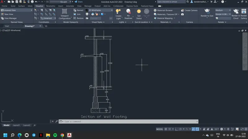
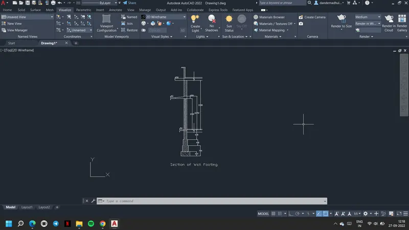
7. Now to form the isometric view of the wall delete tha hatch, dimensionsa nd text as shown
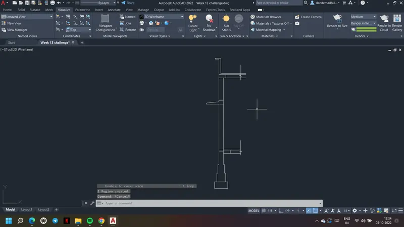
8. Go to boundary Bo command and form the regions for the footing
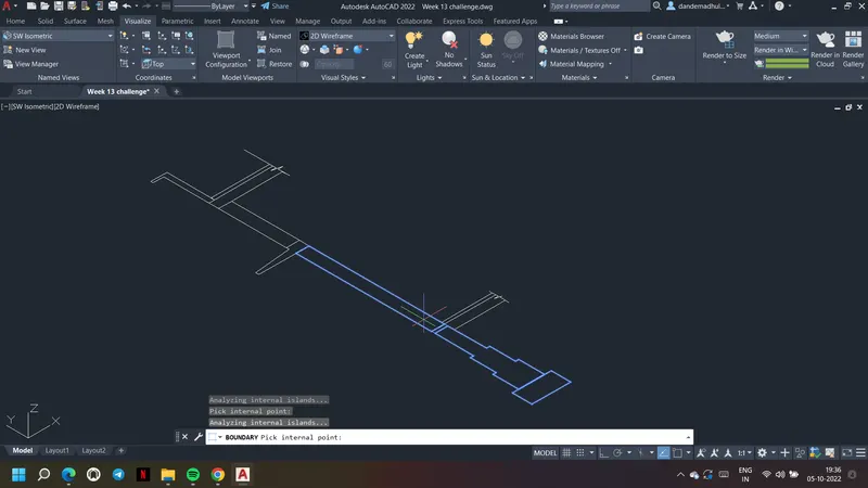
9. After forming total regions extrude them using extrude comamnd upto 7500 as given in the plan of the wall
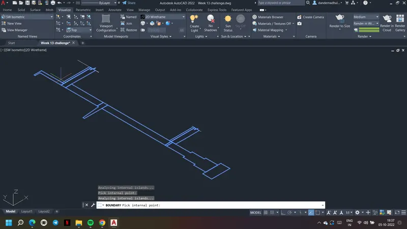
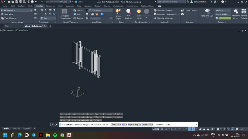
10. Create a door using the line command with the dimensions given in the plan
11. Join the lines to form a rectangle as shown
12. Form a region to this rectangle to extrude it
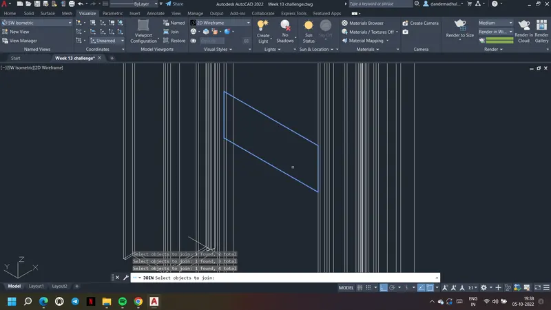
13. Extrude it to certain extent to use the subtract command
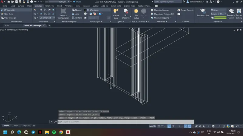
14. Now ise sibtract command and subtract the door from the footind to form door opening
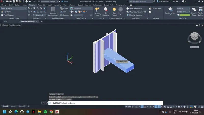
15. Desired door opening is formed as shown
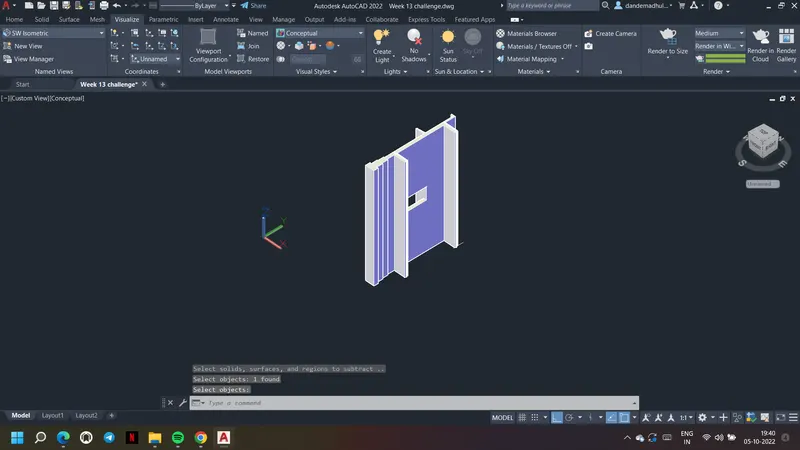
16. It is the isometric view of the wall with the door opening
17. Use explode command to separate the items in the drawing
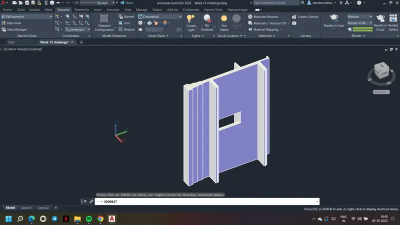
18. Go to material browser and for the footing choose sand material as shown
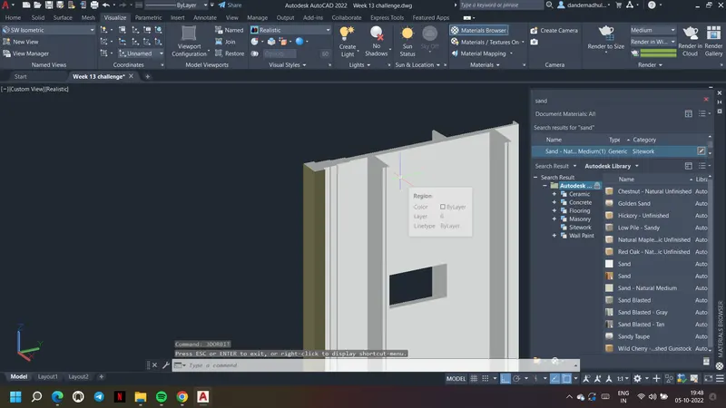
19. For the whole wall choose the brick or stones as desired. Here brick masonry is choosen as material
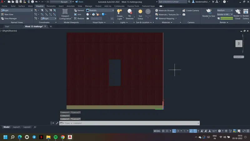
20. the isometric view of the wall
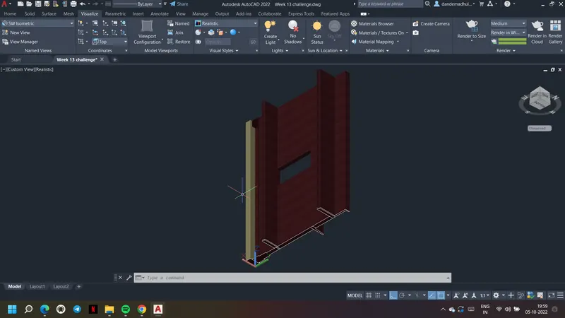
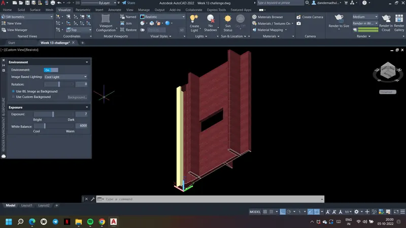
21. Go to render with enviroment and exposure and set the options as required, brightness as required
22. Go to render window and choose accuracy as draft or low or high as required
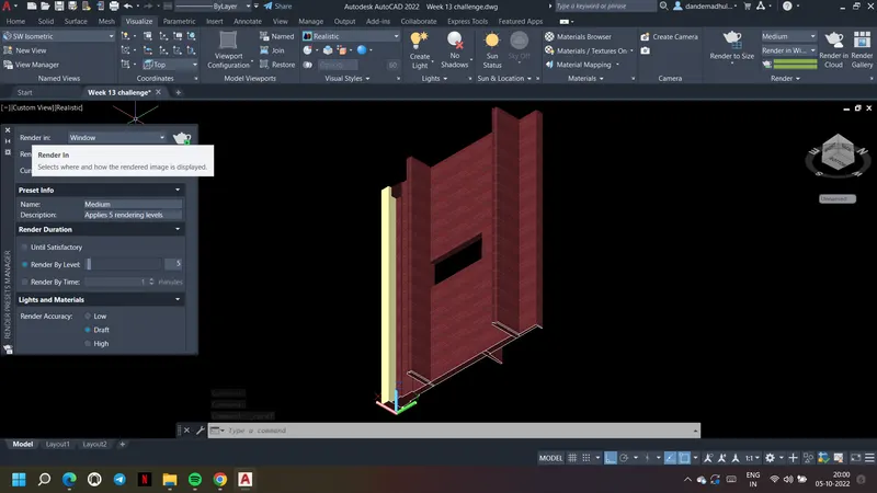
23. Give RR command to form the below shown rendered view
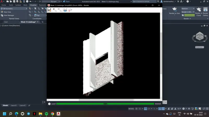
Result: The 3D view of a Wall with spread footing is created along with the door opening. Rendering view view of the model with materials is shown.
21. Go to render with enviroment and exposure and set the options as required, brightness as required