Creating 3D Isometric view of various structural elements in AutoCAD
Q1:
Aim: To create 3D isometric view of the building using AutoCAD.
Procedure:
Type "Units" in the command prompt and press enter.
Select "Architectural" and click ok
Select line tool from ribbon tab and press enter.
Enter the starting point as (0,0) and press enter.
Enter the next point as (@0,10'9") and press enter.
Enter the next point as (@10'9",0) and press enter.
Enter the next point as (@0,-9") and press enter.
Enter the next point as (@-10'0,0) and press enter.
Enter the next point as (@0,-10') and press enter.
Press close.
Type offset in the command prompt and press enter.
Enter the offset distance as required to create a window.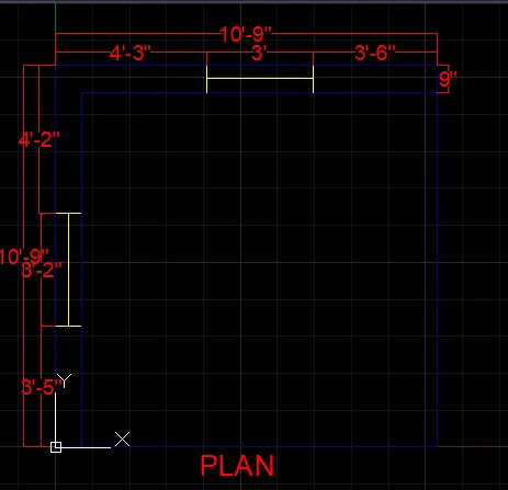
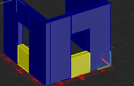
Select extrude tool from ribbon tab.
Select the required objects to extrude and press enter.
Enter the required distance as 10'.
Again select extrude from the ribbon tab.
Now select the window walls.
Enter the required distance as 3'.
Q2:
Aim: To create the 3D view of view of building facade as shown in the plan and elevation using AutoCAD.
Procedure:
Type "Units" in the command prompt and press enter.
Select "Architectural" and click ok
Select line tool from ribbon tab and press enter.
Enter the starting point as (0,0) and press enter.
Enter the next point as (@0,-10'9") and press enter.
Enter the next point as (@6'9",0) and press enter.
Enter the next point as (@0,10'9") and press enter.
Enter the next point as (@-9",0) and press enter.
Enter the next point as (@6'9",0) and press enter.
Enter the next point as (@-6',0) and press enter.
Enter the next point as (@0,-10') and press enter.
Press close.
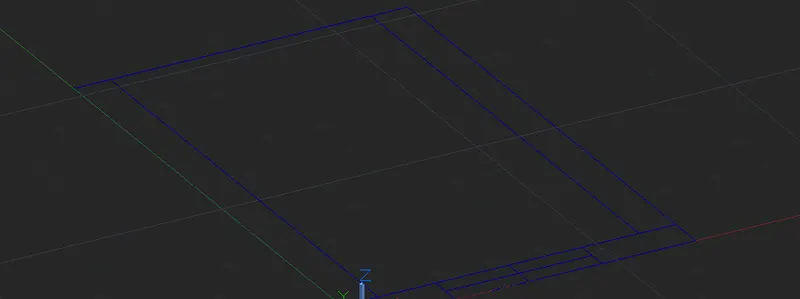
Select the extrude option in the ribbon tab and press enter.
Select the previously created object to extrude.
Enter the distance to extrude.
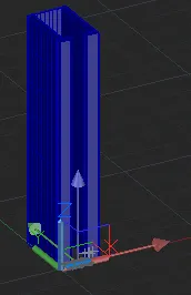
Select the line tool from ribbon tab and press enter.
Specify the starting point as required.
Specify the next point as required.
Similarly use line tool from ribbon tab to create the window.
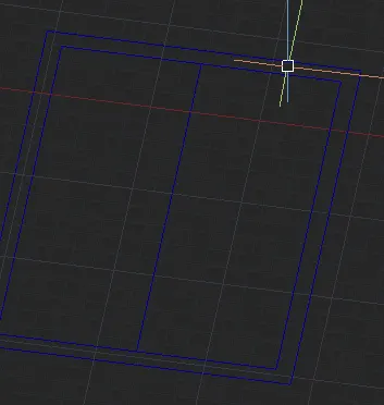
Type dimlinear in the command prompt and press enter.
Specify the starting and ending point to display the dimensions.
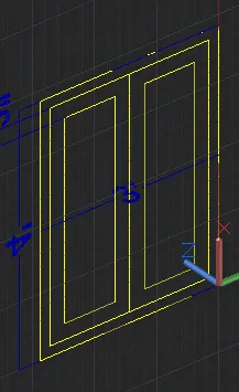
Select the previosuly cretaed object and type move in the command prompt.
Select the basepoint and press enter.
Place the object in the required placce.
Select the previously created object and type copy in the command prompt.
Enter the distance at which the object needs to be placed.
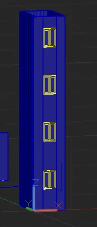
Select the line tool from riibon tab.
Specify the starting point and press enter.
Specify the next point as required.
Select the extrude option from the ribbon tab
Select the previously created object to extrude.
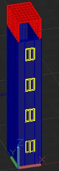
Q3:
Aim: To create the 3D isometric view of stair using Autocad.
Procedure:
Type "Units" in the command prompt and press enter.
Select "Architectural" and click ok
Select line tool from ribbon tab and press enter.
Specify the starting point as (0,0) and press enter.
Specify the next point as (@0,0,6") and press enter.
Specify the next point as (@0,1',0) and press enter.
Press esc.
Select the previously created object and type copy in the command prompt.
Select the suitable basepoint to copy.
Now place the copied object as required.
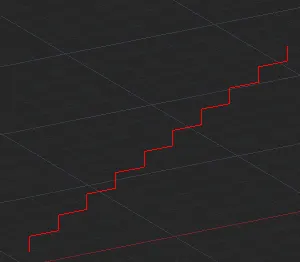
In the coordinates section, select object.
Now select the object about which action should take place.
Select extrude option from ribbon tab.
Select the created object to extrude in X direction.
Next draw a circle using circle command.
Select extrude option from ribbon tab.
Select the created object to extrude in Z direction.
Select the created railing to copy.
Type copy in the command prompt and press enter.
Select the suitable basepoint.
Place the copied object in the required place
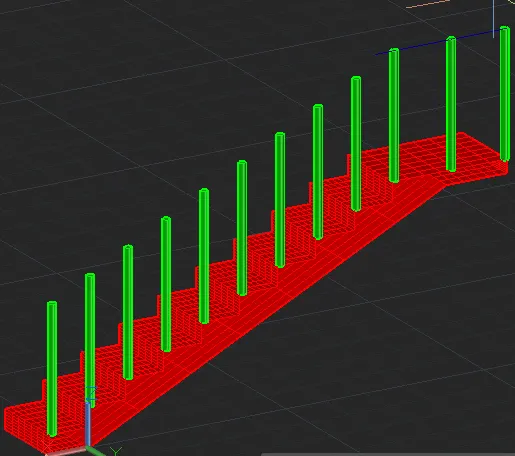
Select line tool from command propmt and press enter.
Draw the required line as per requirement.
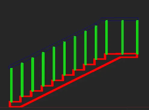
Q4:
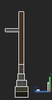
Aim: To create 3D view of wall with spread footing using AutoCAD.
Procedure:
Type "Units" in the command prompt and press enter.
Click on custom view from the workspace.
Select right and click.
Select "Decimal" and click ok
Select rectangle tool from ribbon tab and press enter.
Specify starting point and click dimension from the command prompt.
Press esc.
Select rectangle tool from ribbon tab and press enter.
Specify starting point and click dimension from the command prompt.
Press esc.
Select rectangle tool from ribbon tab and press enter.
Specify starting point and click dimension from the command prompt.
Press esc.
Select rectangle tool from ribbon tab and press enter.
Specify starting point and click dimension from the command prompt.
Press esc.
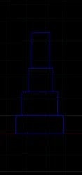
Click on custom view and select Sw view and selct 2d wireframe.
Select rectangle tool from ribbon tab and press enter.
Specify starting point and click dimension from the command prompt.
Press esc.
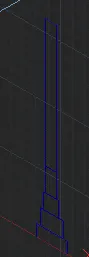
Select extrude from the ribbon tab and press enter.
Select the previously created object and press enter.
Drag the cursor to extrude the object.
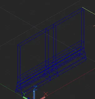
Select rectangle tool from ribbon tab and press enter.
Specify starting point and click dimension from the command prompt.
Press esc.
Change the visual style to shaded.
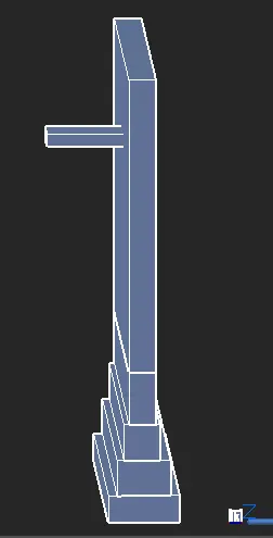
Click o visualize from the ribbon tab.
Select the material browser.
From the select/search the required material.
Click and drag the required material to place on the closed object.