Creating 3D Isometric view of various structural elements in AutoCAD
1.AIM
To create a 3D Isometric view of the building with plan and elevation using the various commands in Auto CAD.
PROCEDURE
- To create a new sheet from application of Auto CAD.
- Go to the setting and to change the view of the page from Drafting to 3D modeling.
- Type ,,UN’ to set the units of current format of measure.( feet and inches).
- Type ,,LIMITS’ to set the maximum dimension limits on the particular page.
- First we take the top view of the page.
- First to create a plan with 2D.
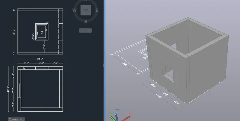
- The dimension of the plan is 10’9” x 10’9”.
- The wall thickness is 9” at standard size of residential building.
- Here we fixed the two windows of the both side of wall
- We have to create the layer properties of understanding the objects like wall, window,text,,etc..,
- After create the 2D plan , let to change the view of 3D modeling with view the any custom views.
- Type ,, BOUNDARY’ to create an all areas in a one boundary to easily extrude the wall.
- Type extrude to create a surface or solid of a 2D surface.
- Here, we take the extruded height is 10 feet.
- Type ,, 3D ORBIT’ to view a 3D orbit viewport in the current viewport.
- Type ,, REC’ to create a rectangle with a given dimensions.
- For here to fix the window before we create the rectangle at bottom of wall and then we extrude the rectangle area.
- Type ,, subtract ‘ to delete the window area for open view.
- To save the diagram to particular file.
RESULTS
The diagram of 3D View of building is drawn as per dimensions using the software of Auto.
DIAGRAM
2.AIM
To create a 3D view of the building Facade using the various commands in Auto CAD.
PROCEDURE
- To create a new sheet from application of Auto CAD.
- Go to the setting and to change the view of the page from Drafting to 3D modeling.
- Type ,,UN’ to set the units of current format of measure.( feet and inches).
- Type ,,LIMITS’ to set the maximum dimension limits on the particular page.
- First we take the top view of the page.
- First to create a plan with 2D.
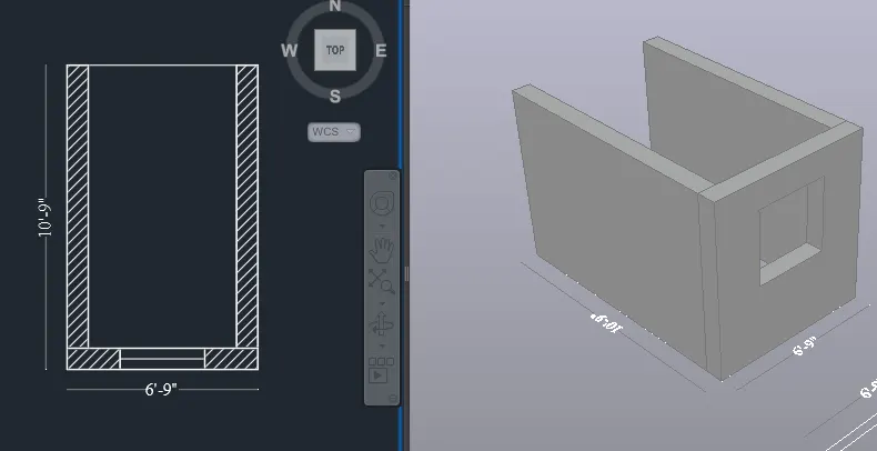
- The dimension of the plan is 6’9” X 10’9”.
- The wall thickness is 9” at standard size of residential building.
- Here, we create a plan and elevation of given dimension.
- The size of the window is 3’0” x 4’2”.
- Take a offset length of from plinth to base of window is 4’6”.
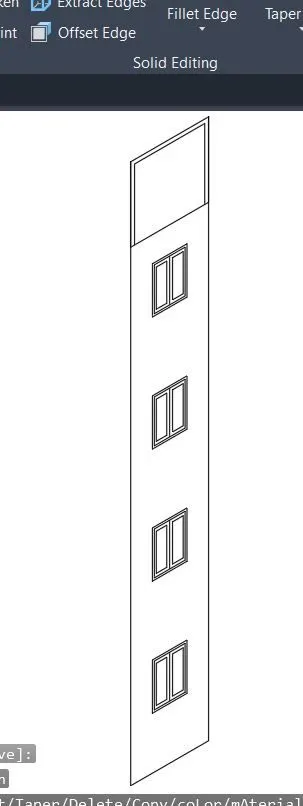
- Let we create an elevation of G+3 building.
- Create a window at standard given dimension.
- Type ,, BOUNDARY’ to create an all areas in a one boundary to easily extrude the wall.
- Type extrude to create a surface or solid of a 2D surface.
- Here, we take the extruded height is 10 feet.
- Type ,, 3D ORBIT’ to view a 3D orbit viewport in the current viewport.
- Type ,, REC’ to create a rectangle with a given dimensions.
- For here to fix the window before we create the rectangle at bottom of wall and then we extrude the rectangle area.
- Type ,, subtract ‘ to delete the window area for open view.
- To save the diagram to particular file.
RESULTS
The diagram of 3D Plan and elevation is drawn as per dimensions using the software of Auto.
DIAGRAM
3.AIM
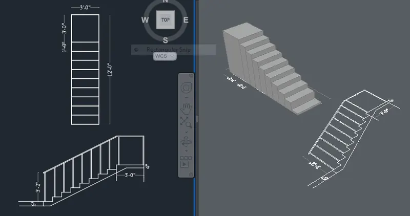
To create a 3D Isometric view of the stair with railing using the various commands in Auto CAD.
PROCEDURE
- To create a new sheet from application of Auto CAD.
- Go to the setting and to change the view of the page from Drafting to 3D modeling.
- Type ,,UN’ to set the units of current format of measure.( feet and inches).
- Type ,,LIMITS’ to set the maximum dimension limits on the particular page.
- First we take the top view of the page.
- First to create a plan with 2D.
- To create a staircase with a standard dimensions
- Tread is 1 feet and Riser is 6 inches.
- The width of the stair is 3 feet.
- The railing is located from the base height is 3 feet and 2 inches.
- Type ,, BOUNDARY’ to create an all areas in a one boundary to easily extrude the Stair.
- Type,, 3DROTATE’ it helps to Rotate the objects in 3D view.
- Type EXTRUDE to create a surface or solid of a 2D surface.
- Here, we take the extruded Width of the stair is 3 feet.
- Type ,, 3D ORBIT’ to view a 3D orbit viewport in the current viewport
- To save the diagram to particular file.
RESULTS
The diagram of 3D Isometric view of stair is drawn as per dimensions using the software of Auto.
DIAGRAM
4.AIM
To create a 3D Isometric view of the wall with spread footingusing the various commands in Auto CAD.
PROCEDURE
- To create a new sheet from application of Auto CAD.
- Go to the setting and to change the view of the page from Drafting to 3D modeling.
- Type ,,UN’ to set the units of current format of measure.( feet and inches).
- Type ,,LIMITS’ to set the maximum dimension limits on the particular page.
- First we take the top view of the page.
- First to create a plan with 2D.
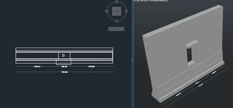
- To create a plan of wall with footing size.
- The footing dimension is taken from the section view of plan at given standard dimensions.
- The length of the wall is 7500mm and height of the wall is 3300 from the base plinth level.
- This footing is designed by two stepped footing and PCC height is 300mm.
- The door size is 900mm x 2100mm.
- After create the 2D plan , let to change the view of 3D modeling with view the any custom views.
- Type ,, BOUNDARY’ to create an all areas in a one boundary to easily extrude the wall.
- Type extrude to create a surface or solid of a 2D surface.
- Here, we take the extruded height is 3300 mm.
- Type EXTRUDE to create a surface or solid of a 2D surface.
- Type ,, REC’ to create a rectangle with a given dimensions.
- For here to fix the DOOR before we create the rectangle at bottom of wall and then we extrude the rectangle area.
- Type ,, SUBTRACT ‘ to delete the window area for open view.
- Here to provide the lintel view also for the given dimension.
- Type ,, 3D ORBIT’ to view a 3D orbit viewport in the current viewport
- To save the diagram to particular file.
RESULTS
The diagram of 3D view of the wall with spread footing is drawn as per dimensions using the software of Auto.
DIAGRAM