Creating 3D Isometric view of various structural elements in AutoCAD
ANSWERS :
AIM : To Create a 3D Isometric View of the building with plan and elevation given.
INTRODUCTION : 3D Modelling of the Given objects are Drawn by AutoCad from three dimensionsal aspect by showing size, area, Height, surface adn Texture from various tools such as Line, Rectangle, Loft, Extrude, subtract, union, UCS, Region, Boundary and other tools
To Cancel Selected Command Press “ESC”
To Invoke Previously Selected Command Press “ENTER”
Make Use of the UCS Option on wherever the Object's Particular View / Face to be Edited
PROCEDURE :
Go to START MENU, select AutoCAD 2022.
In the Command line type in: STARTUP [ENTER]
Enter new value of startup: 1
Go to Application Menu and select New
In the 'Create New Drawing' dialog box, we do the Advanced Setup and select the 'Engineering' unit of measurement and select precision as 0'-0.0"
Enter 'UNITS' command in the command tab.
In the Drawing Units dialog box, select 'Engineering' in Type; 0'-0" in Precision; and 'Inches' in Insertion scale.
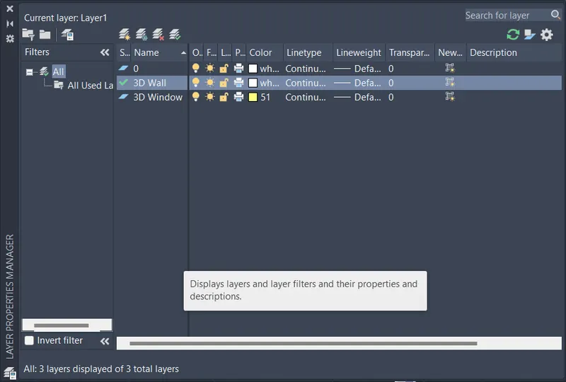
LAYERS : Create the Requied Layers
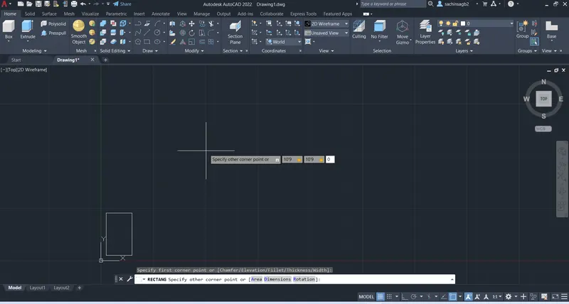
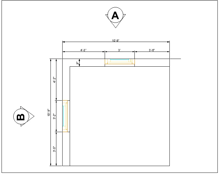
RECTANGLE : Specify the first point of the Rectangle and Specify the other as 10'9,10'9
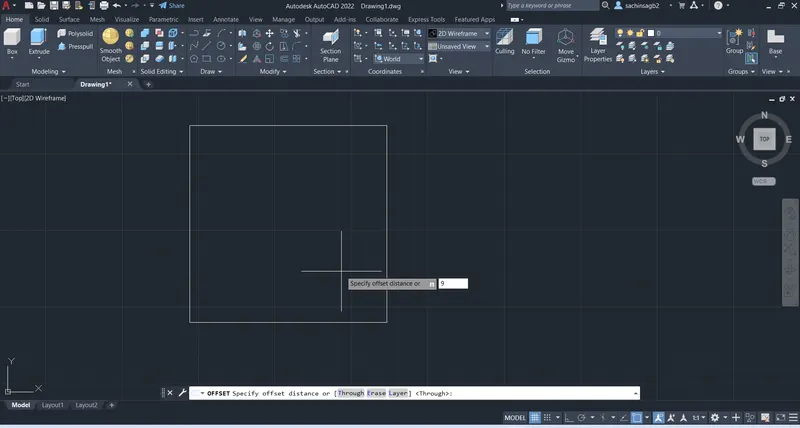
OFFSET : Specify the Offset distance of 9"
EXPLODE: Select and Explode the Rectangle
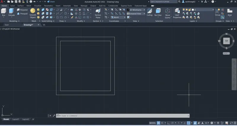
CUT :select and Cut the unwanted lines
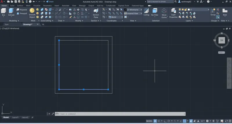
EXTEND : Select and Extend Lines
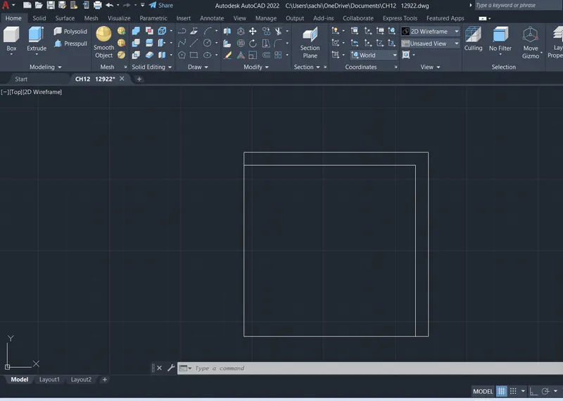
XLINES : Create and Place the Construction lines Vertical and Horizontally at a Distance of Window placements
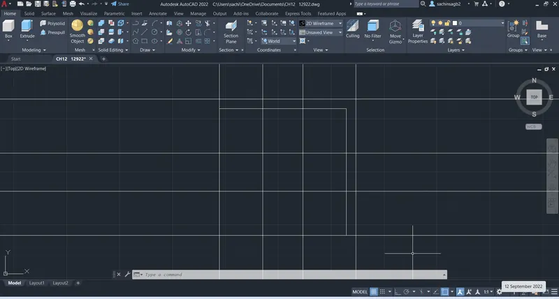
TRIM : Select and Trim the unwanted lines
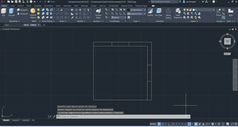
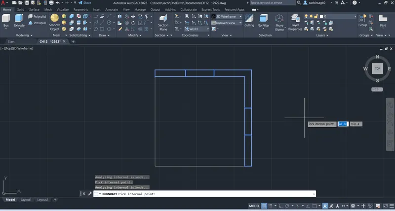
BOUNDARY : Select and Pick internal point of Boundary to be created
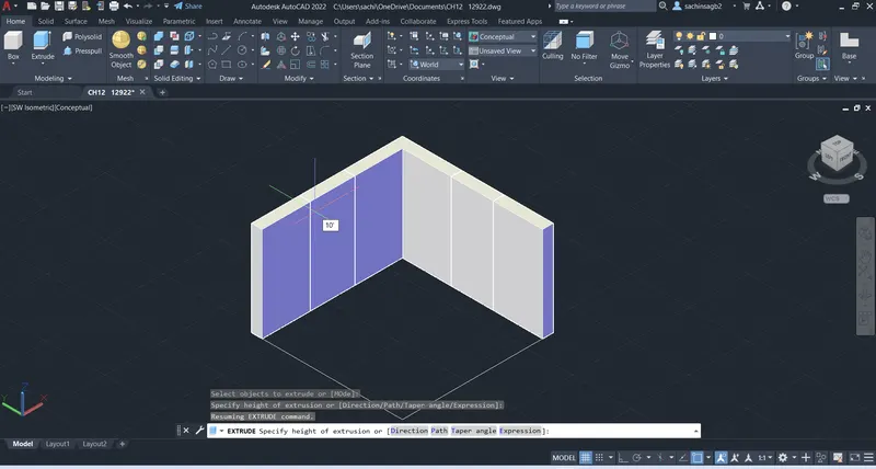
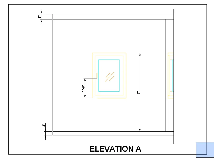
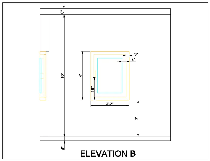
EXTRUDE : Extruded the wall at a height of 10'
UNION : Select and Unite the object
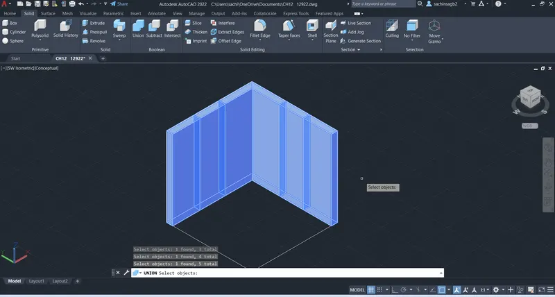
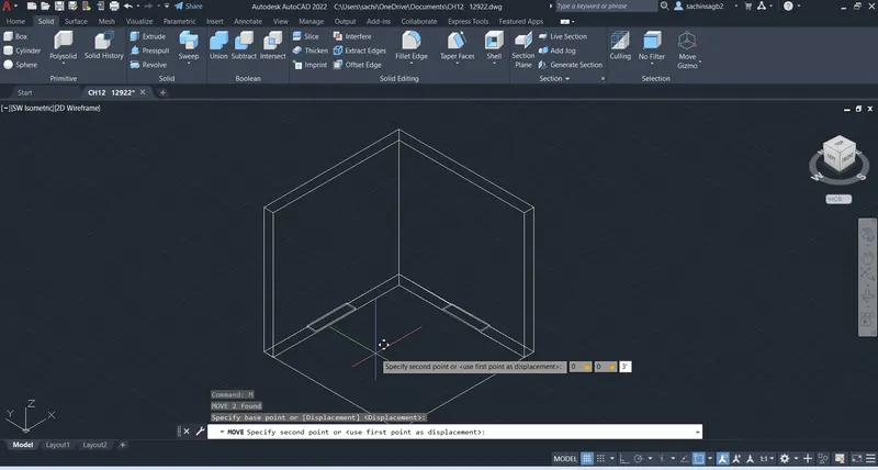
MOVE : Select the window rectangles and move it to the height of 3'
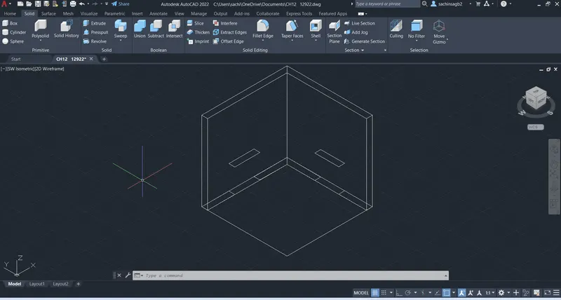
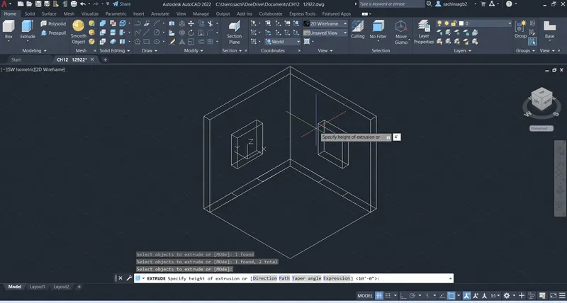
EXTRUDE : Extruded the window at a height of 4'
SUBTRACT : Select Total object and click Enter then select the object to be Subtracted
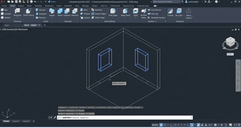
Now the Window opening has been Created
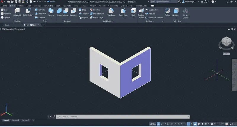
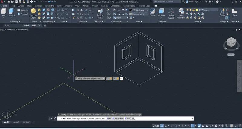
To Create a Window frame Select the Rectangle option and create the Rectangle over the Opening from by keeping the UCS on the face of the wall
OFFSET: Create the offset of 4"
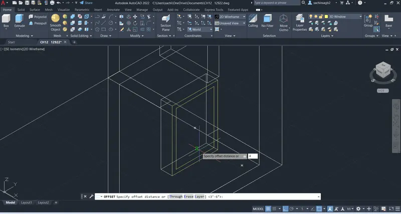
Similarly Create the Different multiple rectangle of different sizes from offset option to create the Frame
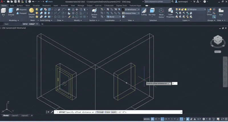
LAYER : Select the Desired Layer and object to distinguish the frame, glass and other objects
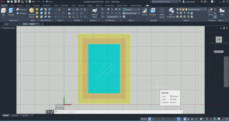
Extrude : select and Extrude each and every objects of windows of their appropriate thickness
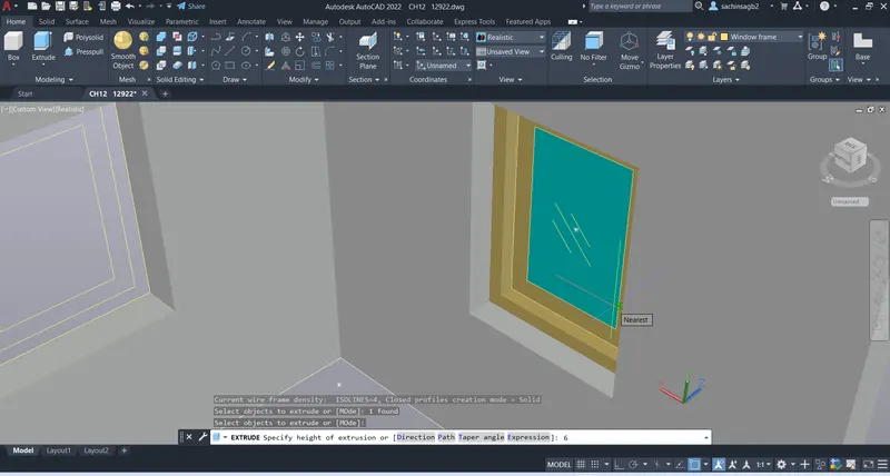
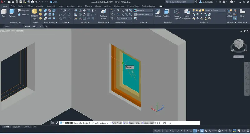
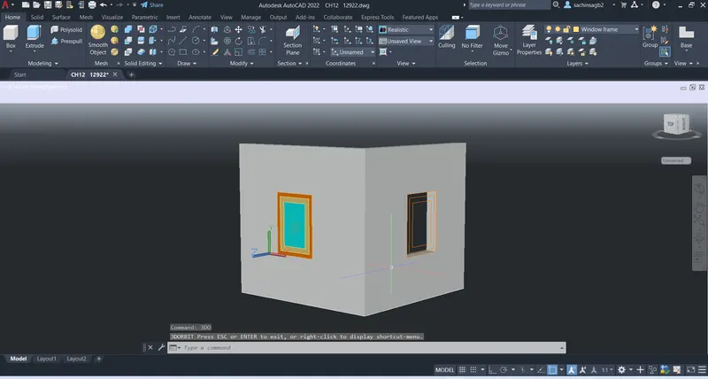
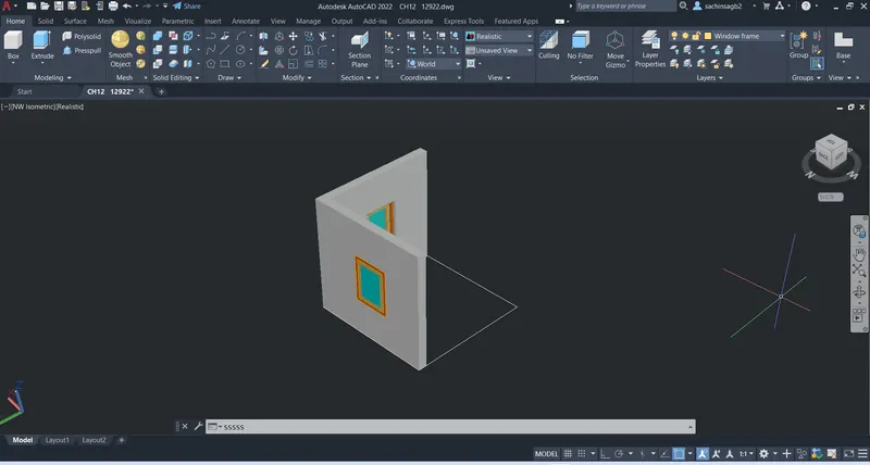
UCS : Select and place ucs on the Face of wall
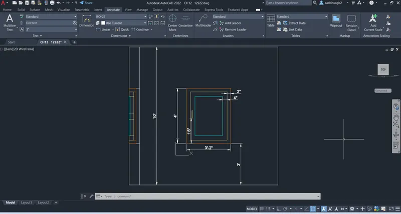
ANNOTATION : select and place the Required Dimensions
DIMST : customise the annotation Style and sizes
RESULT :
PLAN
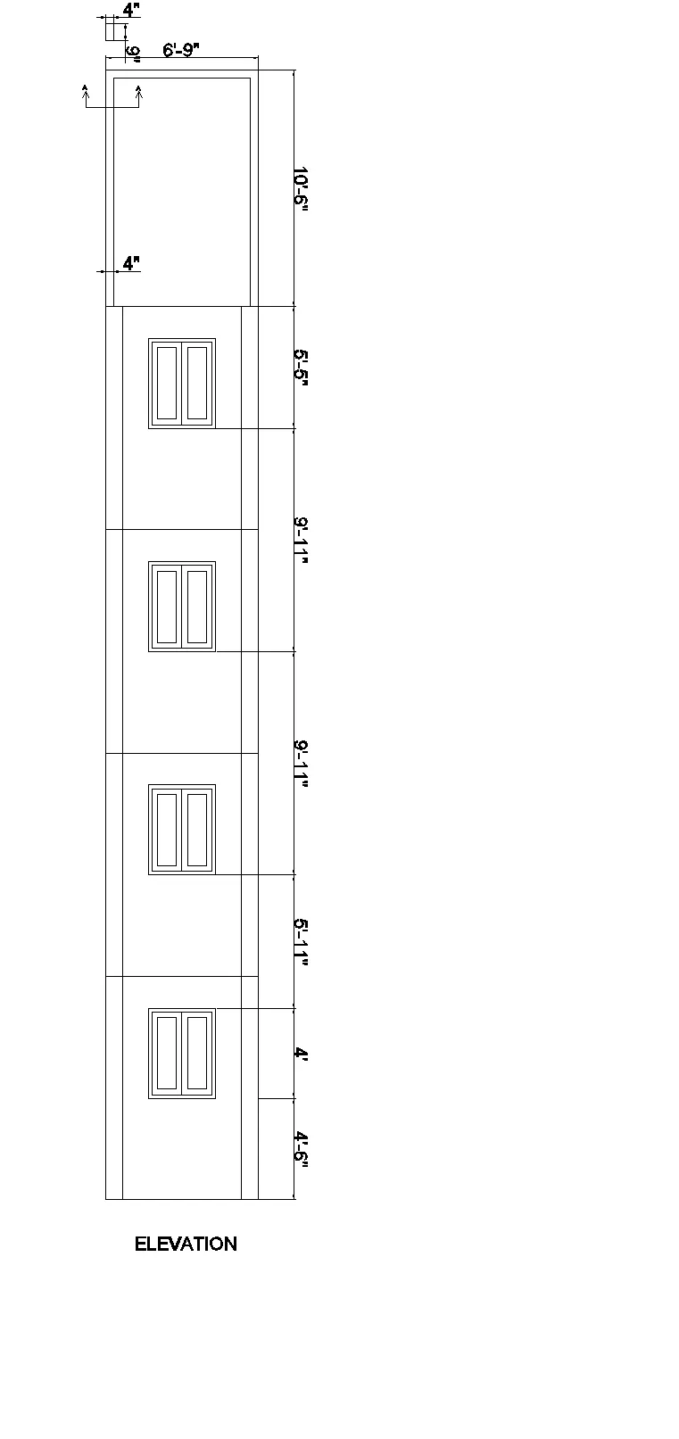
ELEVATION A
ELEVATION B
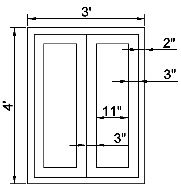
AIM : To Create the 3D View of the Building Façade as given in the plan and elevation. Also, see the detail of the window.
RECTANGLE :Specify the Dimension of rectangle as 10'9,6'9
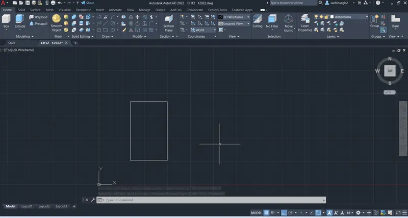
OFFSET : Specify the offset distance as 9"
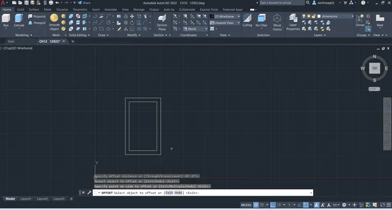
EXPLODE :select the inner rectangle and Explode , and trimoff the unwanted side of rectangle
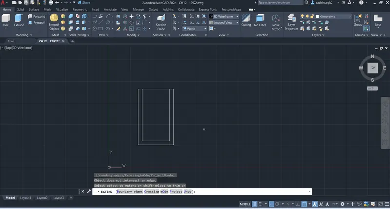
OFFSET: use the offset of option to create the window placement
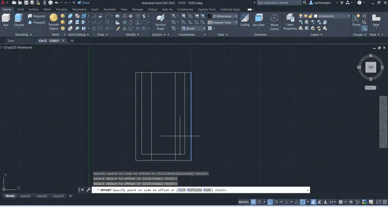
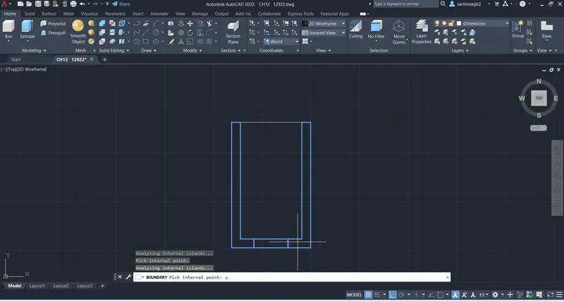
EXTRUDE: Specify the offset distance as 9'11"
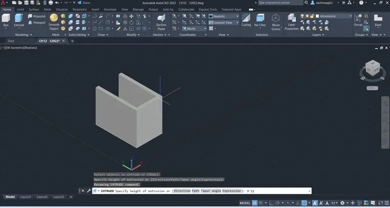
MOVE : select and lift the window from the plan
Rectangle : Create the Window frame
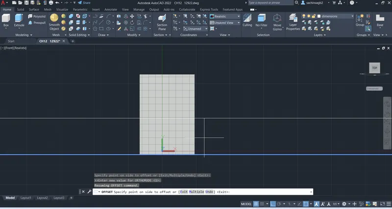
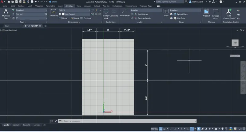
SUBTRACT : Select the Face of the wall and Subtract the Window portion
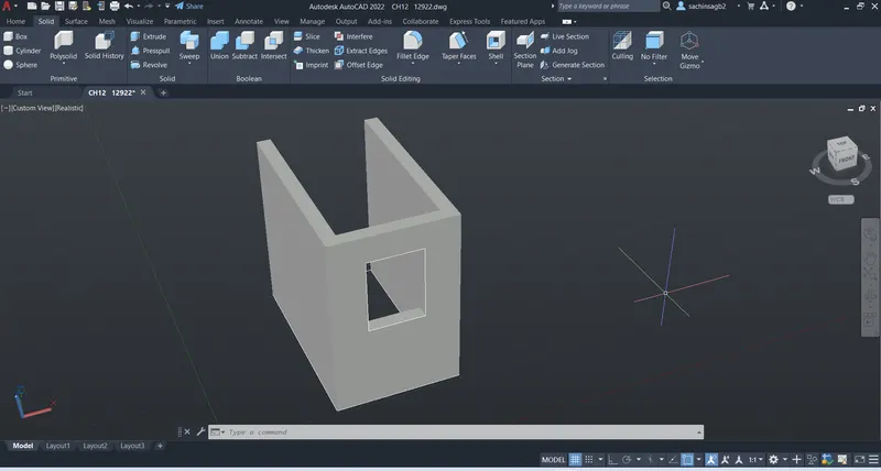
Prepare the Window frame by as mentioned in previous object
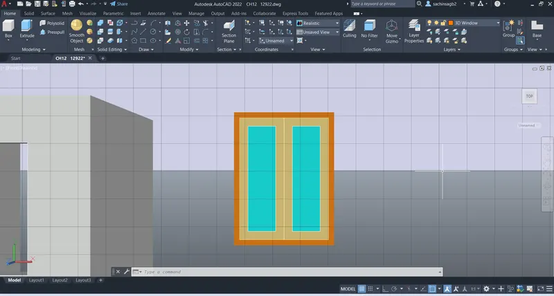
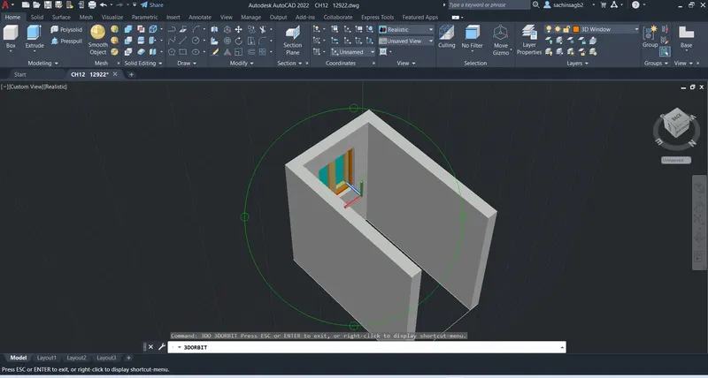
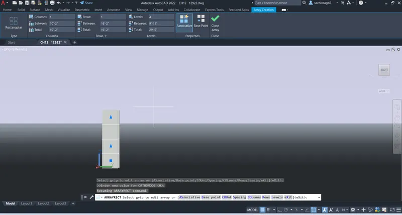
ARRAY : Select the object and Array the object as mentioned in below clipping
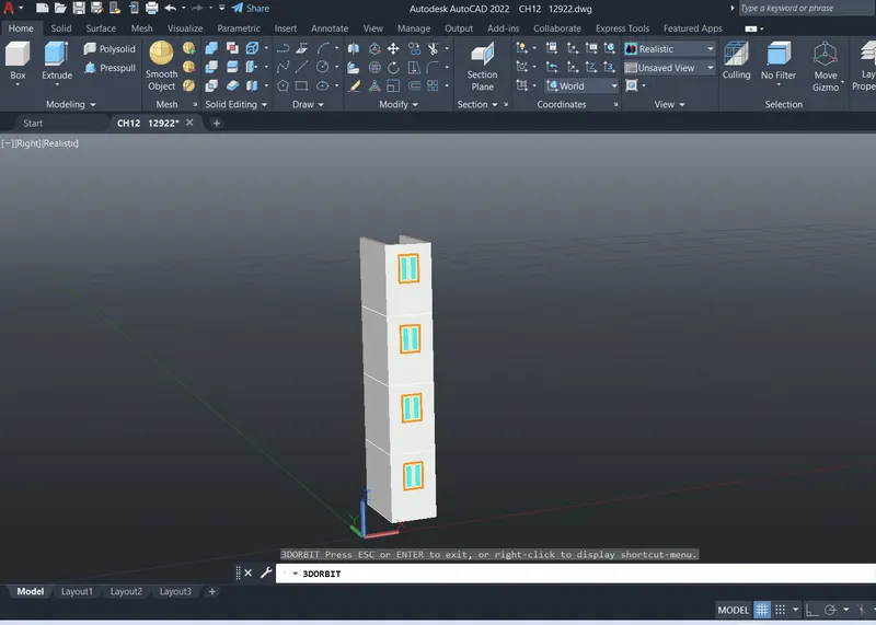
place the ucs on the top face of the wall
RECTANGLE : create the rectangle of size 9"x4 "
LINE : Create the line of length 6'5" in upward direction and 6'9" in right and 6'5" in Downward direction
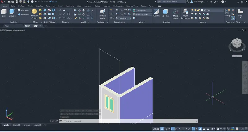
REGION : Specify the rectangle as a region
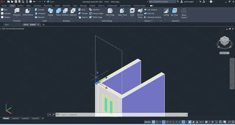
LOFT : Specify the Lofting object as rectangle
Specify the Lofting path as Line to create the object as shown in figure
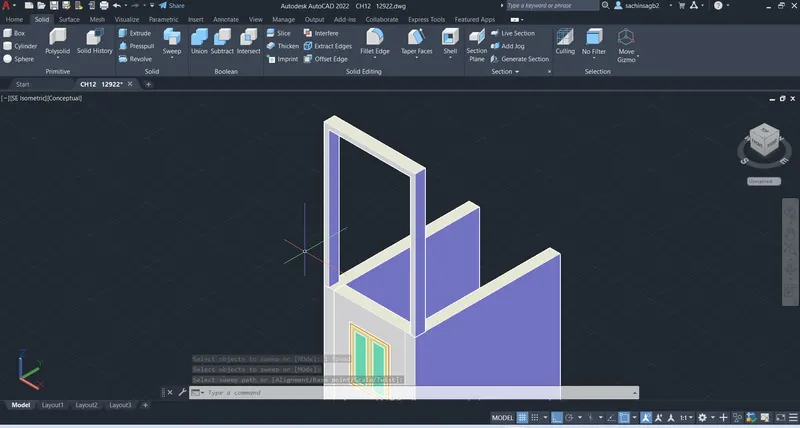
ANNOTATION : select and place the Required Dimensions
DIMST : customise the annotation Style and sizes
RESULT :
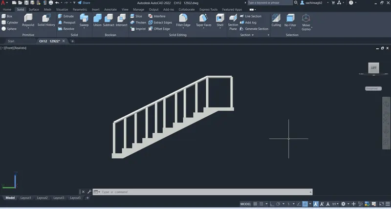
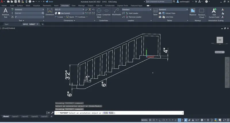
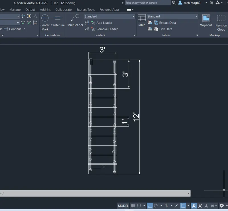
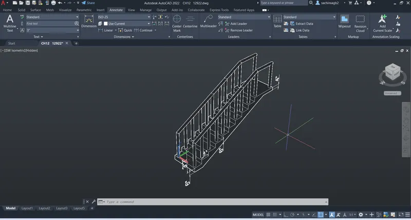
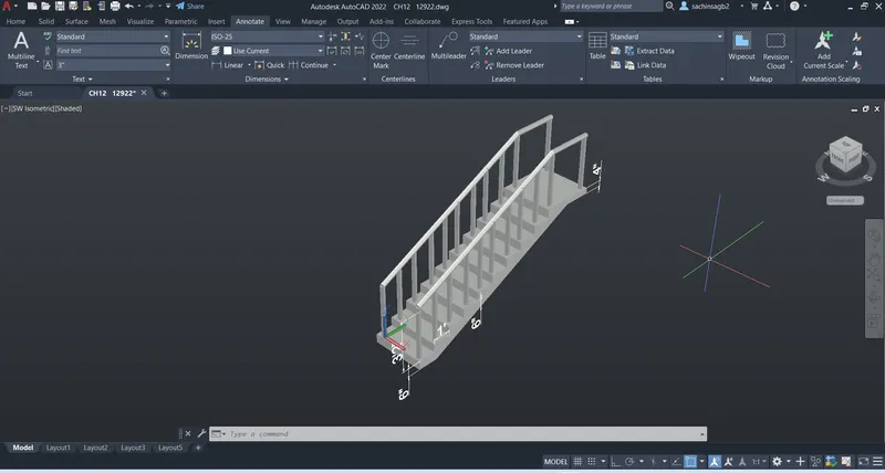
AIM : To Create the ismoteric 3d view of a stair with railing as shown in the plan and elevation. Assume the size of the balustrades and the hand rails.
LINE : select the Line tool and Create the Steps of Riser 6" and Tread as 12", Landing length as 36" as shown in figure
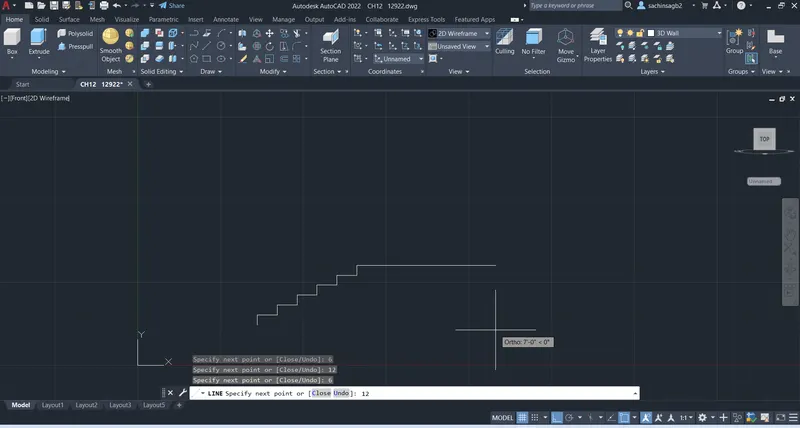
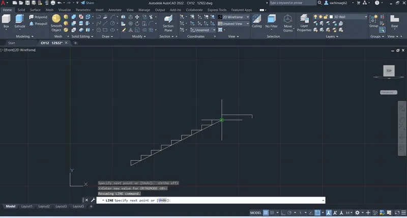
LINE : Connect all the Riser lines as Shown in figure and create the waist slab thickness as 4"
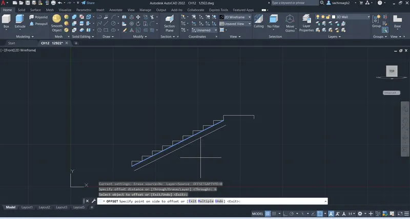
OFFSET: Select the line and offset it by 6"
CHAMFER : Select offsetted line and waist slab line to make it as connected line
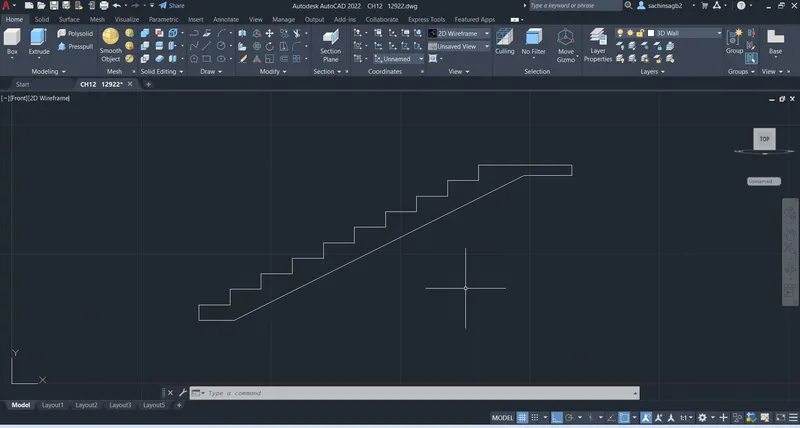
REGION : select the object boundary and create the region
EXTRUDE : Specify the extrude length as 36"
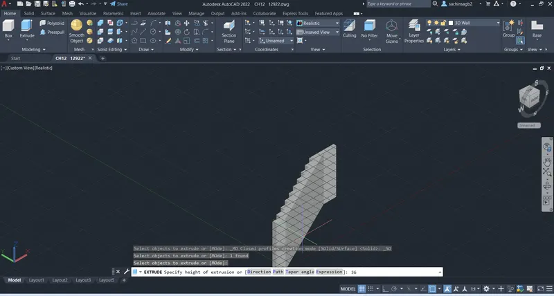
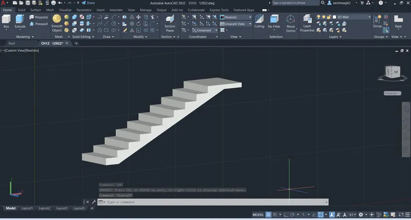
Now place the ucs on first tread and
CIRCLE : Create the Railing baluster circle
REGION: select the circle and Create as a region
EXTRUDE : extrude the circle as 36"
COPY : Copy and paste the baluster on all Steps
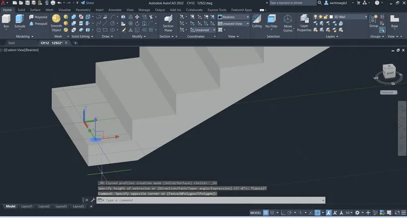
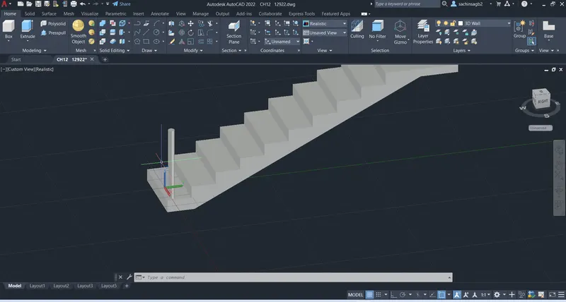
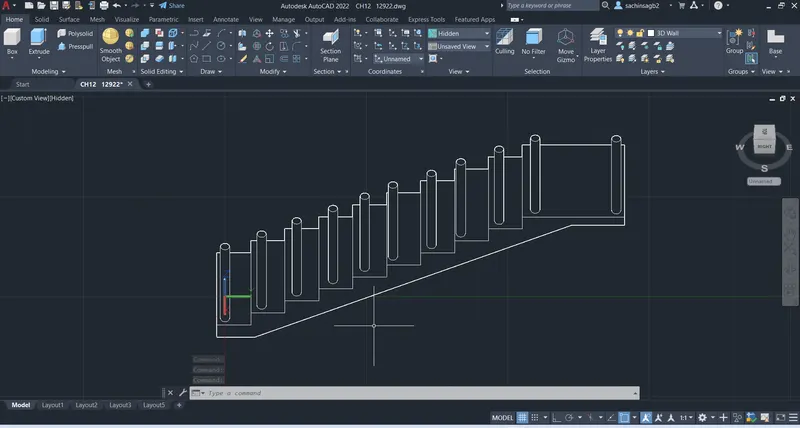
LINE: create the line along all the top portion of baluster
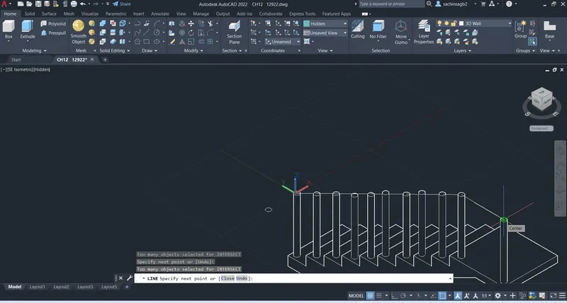
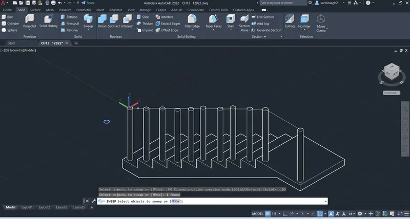
SWEEP : Select the object as circle and sweep path as Line to create the Railing
Now the Railing is created, Copy the whole Railing on other side of the staircase
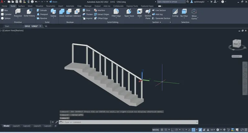
ANNOTATION : select and place the Required Dimensions
DIMST : customise the annotation Style and sizes
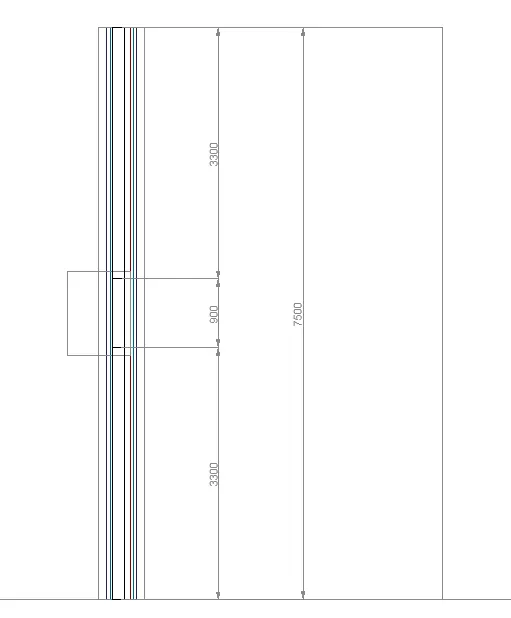
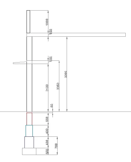
4. To Create the 3D view of a Wall with spread footing . Create the Door opening only. Assume the size of
the parpaet and the coping. See the plans and elevation for the details. Also, create a rendered view of
the model with materials as of your choice.
Enter 'UNITS' command in the command tab.
In the Drawing Units dialog box, select 'Engineering' in Type; 0'-0
RECTANGLE : Specify the start point of the rectangle as 0,0,0 and 600, 0, 300
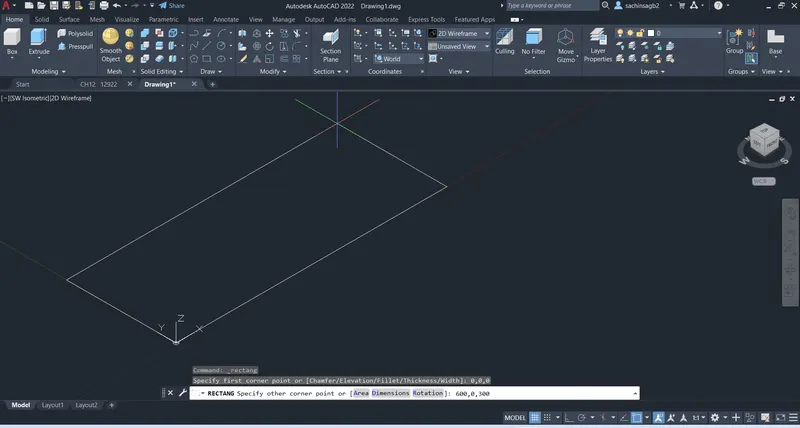
Similarly Create the other Rectangles as specified Dimensions To create object
REGION : select the object and Create the region
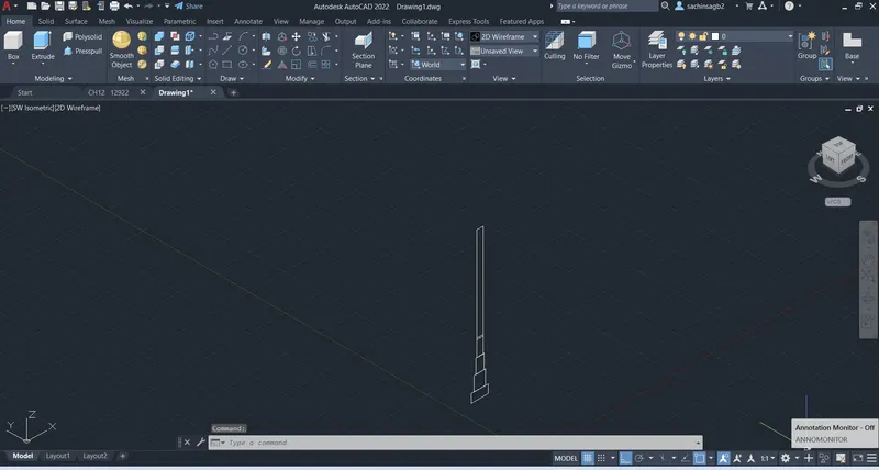
LINE :Create the line of length 7500
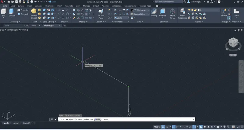
SWEEP : Select the object as sweep object and Sweep path as Line
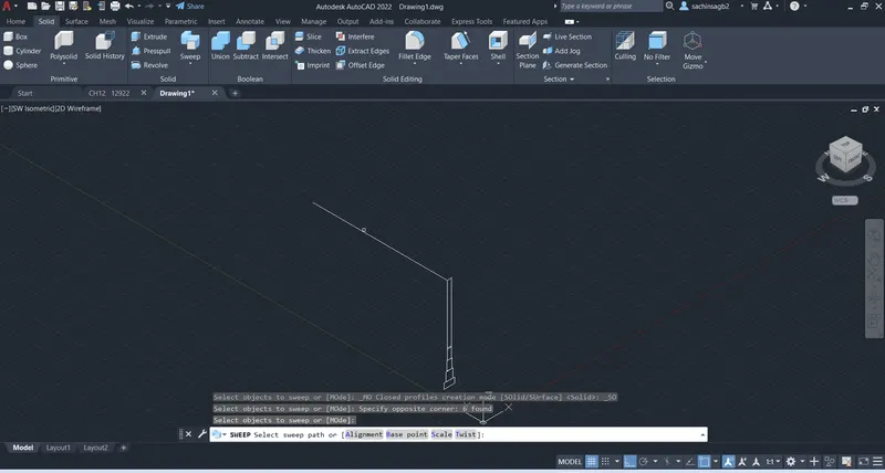
Now the wall and footing has been Created
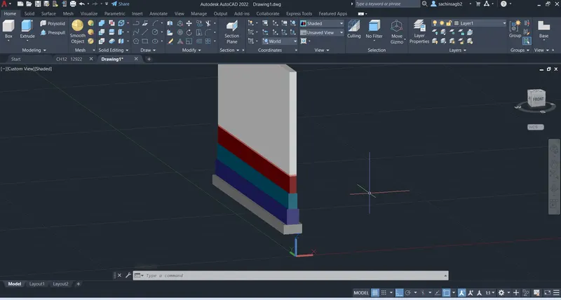
LINE: Create the line to create the Door frame
SUBTRACT : Select whole object click Enter and now select only the door Frame to subtract and make opening
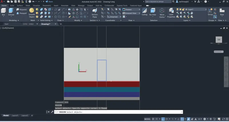
Now the Door opening Created
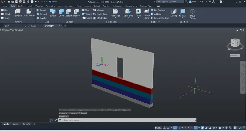
LINE : To Create the Chajja Thickness of Lintel as 150, Projection of Chajja as 600, Thickness 100 & 50
Create the object as shown in Figure
EXTRUDE : Extrude the Chajja to the Lenth of 1200
MOVE : move the chajja and place it at the centre of the door, so as to provide the Projection of 150mm on the either side
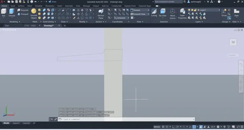
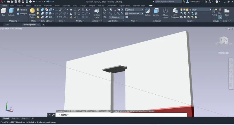
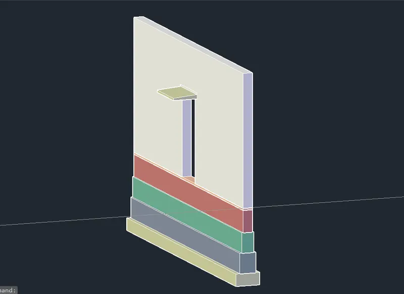
RECTANGLE : Now Create the Slab and Parapet wall by Creating the Rectangle, making it as the Region and Then Extrusion as shown in figure
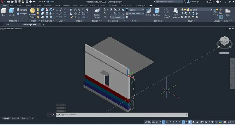
RESULT: