Creating 3D Isometric view of various structural elements in AutoCAD
Aim: - To Create a 3D Isometric View of the building with plan and elevation given using AutoCAD 3D.
Introduction: - The 3D Isometric View of the building with plan and elevation is drawn using proper 3D tools, primarily using the Line tool and after sketching, the dimensions and text are provided. The procedure of drawing is explained in detail with diagrams of each step and the final result is given.
All dimensions are taken in inches.
PROCEDURE: -
Before we start the drawings we need to set up the drawing as Engineering and the units into Imperial Units.
Following are the steps in order to set up the drawing as Imperial Template and the units into Engineering Units.
- Go to Application Menu or click CTRL + N (New)
- Click on New from the Application Menu
- A popup menu appears, click on the first tab known as Start from Scratch > Select imperial
- Now click on the third tab known as Use a Wizard > Go to Advance setup > A Dialog box appears > Select the unit of measurement as Decimal > Press Next > select Angle as Decimal Degrees > Press Next > Select Angle Measure > Press Next > Select Angle Direction > Press Next > Select Area > Click Finish
- Set the page limit by entering Limits in the command tab. The lower left corner is specified as 0,0 and the upper right corner is specified as 100', 100'.
- In the Drawing Units dialog box, select 'Engineering' in Type; ' 0 ' in Precision; and 'Inches' in Insertion scale.
- Click OK
Now,
- Click on the Workspace Switching Tab
- Change the workspace from 2D drafting and annotation to 3D Modelling.
- Now we are all set to go.
Now,
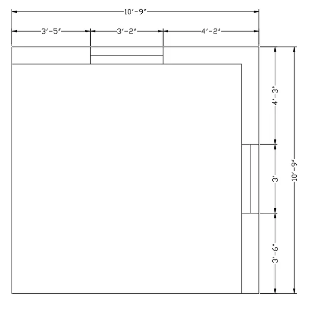
- Draw the plan
- Go to top view and 2-D wireframe.
- Draw 10'9" rectangle.
- Take offset of 9" thickness for the wall.
- Do offset on only two sides of teh wall, i.e., one horizontal and one vertical
- Draw the window at a distance of 3'5" in the horizontal wall.
- Take the window width as 3'2".
- Draw a window at a distance of 3'6" in teh vertical wall.
- Take the width of the window as 3'.
Now,
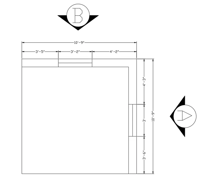
- Draw the sections blocks as is shwon in the drawing.
- Draw a circle of required diameter.
- Type ATT for attribute
- Give the requir3D attributes.
- Now type block
- Select the entire drawing as the block.
- Type I enter and insert the block.
Now,
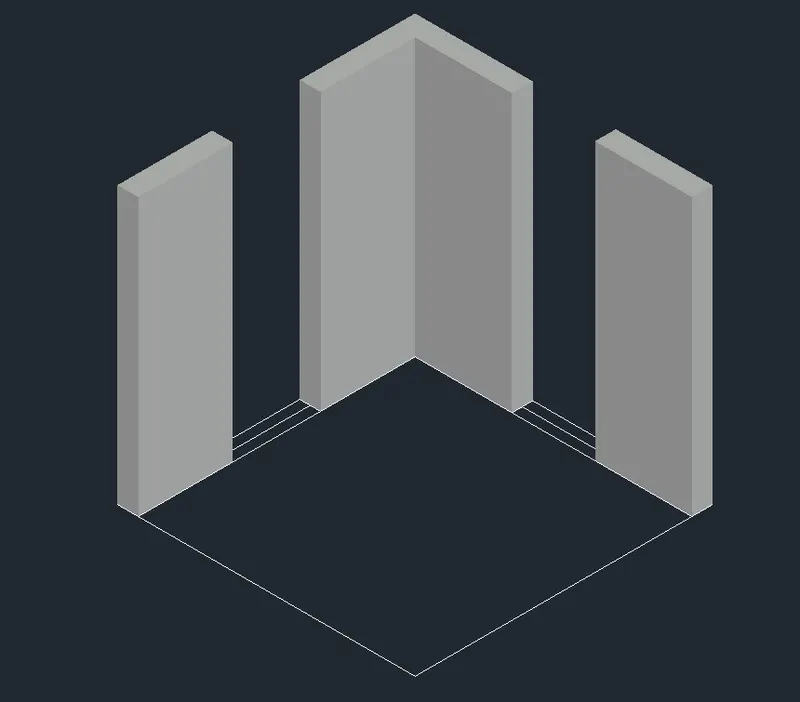
- Draw the elevation
- Go to SW Isometric view.
- Type region and select the area to be regioned.
- Type Extrude to extrude the wall.
- Extrude to a height of 10'
Now,
- Draw the window
- Go to 2D wireframe.
- First draw the window in 2D.
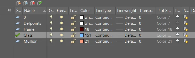
- Take different layers of the window as below,
- Extrude it to height of 4'.
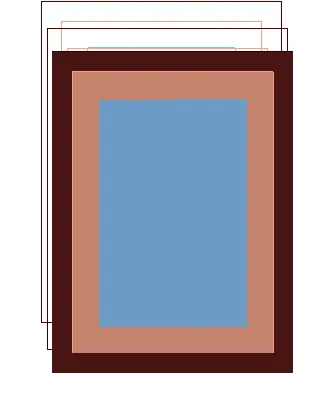
- Put the window in the above 3' sill level.
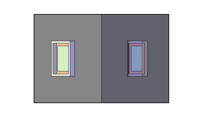
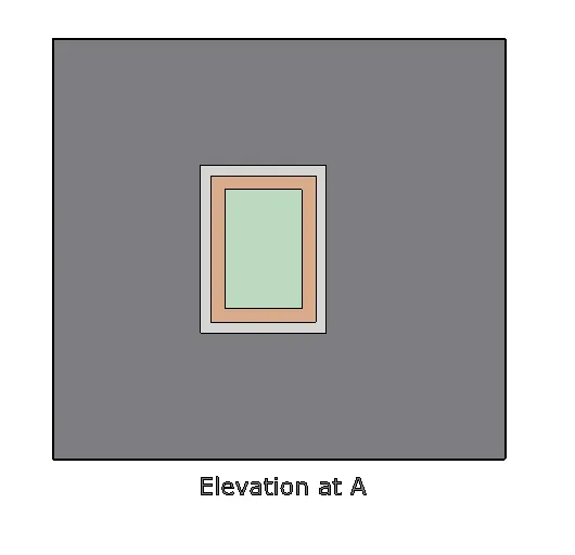
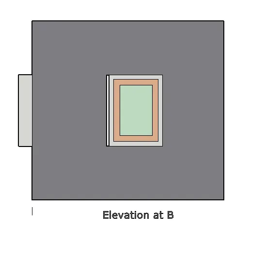
So we have the following results: -
---------------------------------------------------------X-----------------------------------------------------------------------------
Aim: - To Create the 3D View of the Building Façade as given in the plan and elevation given using AutoCAD 3D.
Introduction: - The 3D View of the Building Façade is drawn using proper 3D tools, primarily using the Line tool and after sketching, the dimensions and text are provided. The procedure of drawing is explained in detail with diagrams of each step and the final result is given.
All dimensions are taken in inches.
PROCEDURE: -
Before we start the drawings we need to set up the drawing as Engineering and the units into Imperial Units.
Following are the steps in order to set up the drawing as Imperial Template and the units into Engineering Units.
- Go to Application Menu or click CTRL + N (New)
- Click on New from the Application Menu
- A popup menu appears, click on the first tab known as Start from Scratch > Select imperial
- Now click on the third tab known as Use a Wizard > Go to Advance setup > A Dialog box appears > Select the unit of measurement as Decimal > Press Next > select Angle as Decimal Degrees > Press Next > Select Angle Measure > Press Next > Select Angle Direction > Press Next > Select Area > Click Finish
- Set the page limit by entering Limits in the command tab. The lower left corner is specified as 0,0 and the upper right corner is specified as 100', 100'.
- In the Drawing Units dialog box, select 'Engineering' in Type; ' 0 ' in Precision; and 'Inches' in Insertion scale.
- Click OK
Now,
- Click on the Workspace Switching Tab
- Change the workspace from 2D drafting and annotation to 3D Modelling.
- Now we are all set to go.
Now,
- Draw the plan
- Go to top view and 2-D wireframe.
- Draw 10'9" vertical line.
- Take offset of 9" thickness for the wall.
- Draw 6'9" horizonatl line.
- Take offset of 9" thickness for the wall
- Draw 10'9" vertical line.
- Take offset of 9" thickness for the wall.
- Draw the window at a distance of 1'11" in the horizontal wall.
- Take the window width as 3'.
- Do a solid hatching ANSI32
- Take the height of the window as 4'.
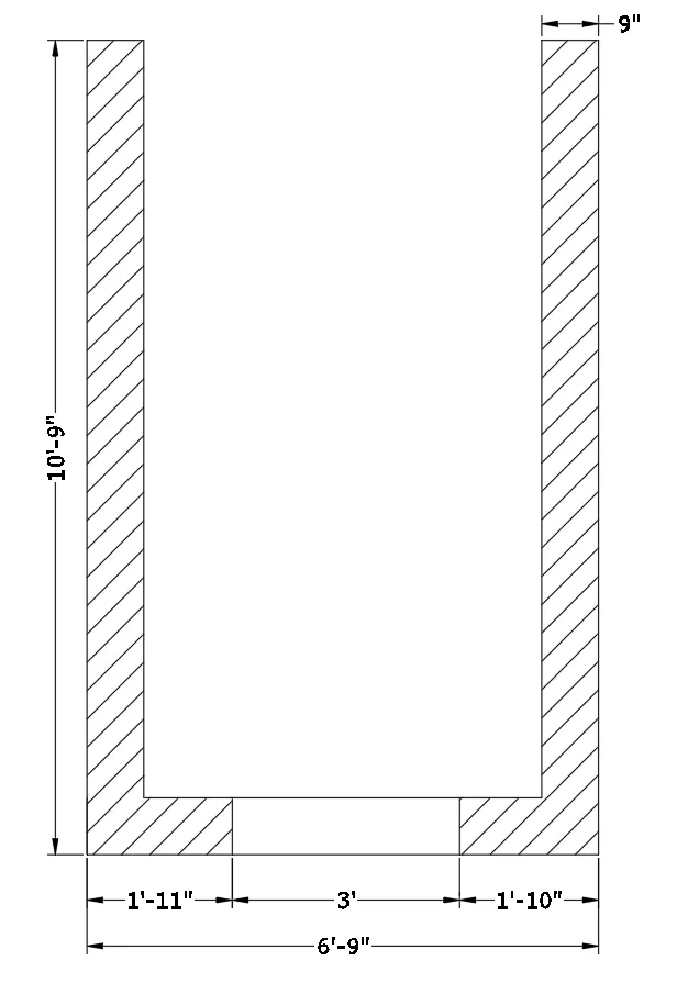
Now,
- Draw the elevation
- Go to SW Isometric view.
- Type region and select the area to be regioned.
- Type Extrude to extrude the wall.
- Extrude to a height of 10'
- Take the wall layer as yellow.
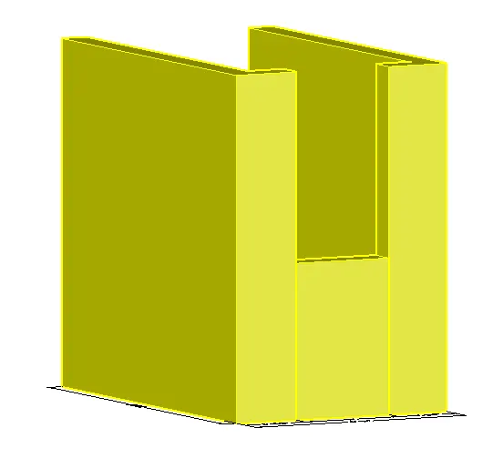
Now,
- Draw the window
- Go to 2D wireframe.
- First draw the window in 2D.
- Take different layers of the window as below,
- Extrude it to height of 4'.
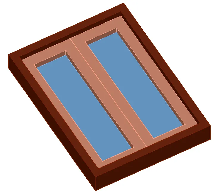
- Put the window in the above 4'6" sill level.
- Union the walls.
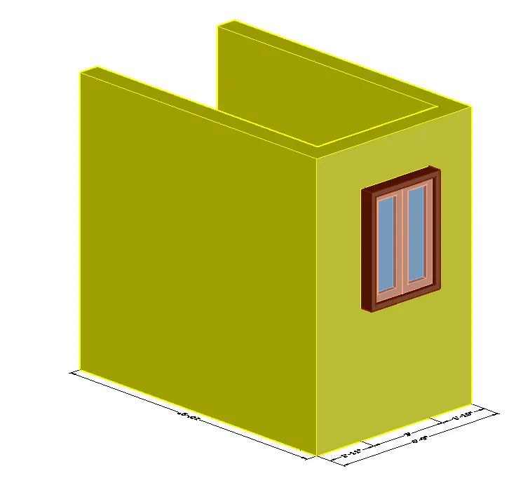
Now,
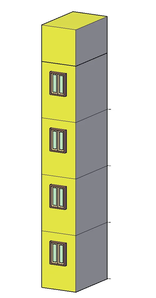
- Copy the above drawing 3 times to create 4 story building.
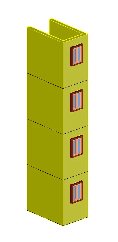
- Draw the upper part.
So we have the following results: -
---------------------------------------------------------X-----------------------------------------------------------------------------
Aim: - To Create the ismoteric 3d view of a stair with railing as shown in the plan and elevation given using AutoCAD 3D.
Introduction: - The ismoteric 3d view of a stair with railing is drawn using proper 3D tools, primarily using the Line tool and after sketching, the dimensions and text are provided. The procedure of drawing is explained in detail with diagrams of each step and the final result is given.
All dimensions are taken in inches.
PROCEDURE: -
Before we start the drawings we need to set up the drawing as Engineering and the units into Imperial Units.
Following are the steps in order to set up the drawing as Imperial Template and the units into Engineering Units.
- Go to Application Menu or click CTRL + N (New)
- Click on New from the Application Menu
- A popup menu appears, click on the first tab known as Start from Scratch > Select imperial
- Now click on the third tab known as Use a Wizard > Go to Advance setup > A Dialog box appears > Select the unit of measurement as Decimal > Press Next > select Angle as Decimal Degrees > Press Next > Select Angle Measure > Press Next > Select Angle Direction > Press Next > Select Area > Click Finish
- Set the page limit by entering Limits in the command tab. The lower left corner is specified as 0,0 and the upper right corner is specified as 100', 100'.
- In the Drawing Units dialog box, select 'Engineering' in Type; ' 0 ' in Precision; and 'Inches' in Insertion scale.
- Click OK
Now,
- Click on the Workspace Switching Tab
- Change the workspace from 2D drafting and annotation to 3D Modelling.
- Now we are all set to go.
Now,
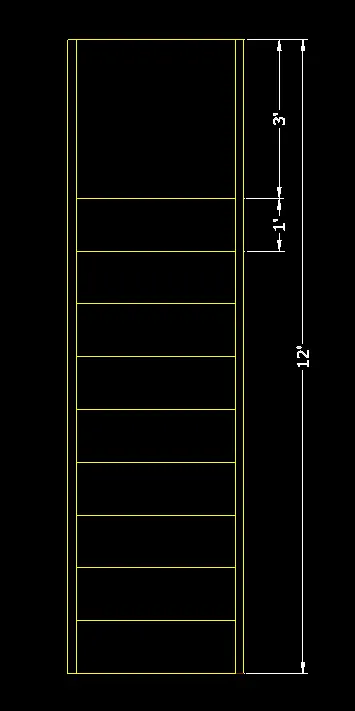
- Draw the plan
- Go to top view and 2-D wireframe.
- Draw 12' vertical line.
- Take offset of 2" thickness for the Baluster.
- Take offset of 3' of the vertical line.
- Take offset of 2" thickness for the Baluster.
- Take 3' landing.
- Draw 9 steps taking offset at a distance of 1' each.
- So we have the following drawing.
Now,
- Type Boundary
- Go to regions
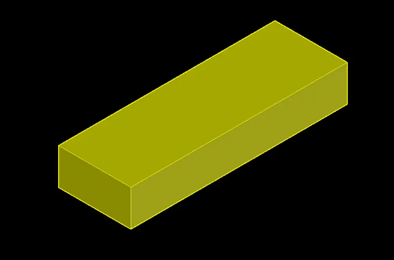
- Select the above plan and make it a region.
- Go to extrude
- Select one stair
- Extrude it to 6".
Now,
- Go to UCS.
- Select Face and set the ucs on the stairs riser.
- Press accept
- Draw a circle of 2"
- Extrude it to 3'.
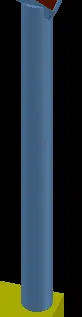
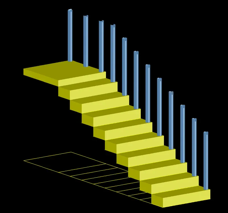
- Copy the one stair along with the baluster
- Paste it according to teh number of stairs.
- So we have the following drawing.
Now,
- Draw the handrail
- Set the UCS in parallei to teh riser.
- Type L or line
- Draw a line from the 1st to the end of the last Baluster.
- Then Type rec or rectangle
- Draw a 2" X 1" rectangle
- Move it to the at the top of the first baluster.
- Then Select Sweep from the ribbon tab.
- Select Object that is rectangle.
- Press enter
- Then select the path.
- Press Enter.
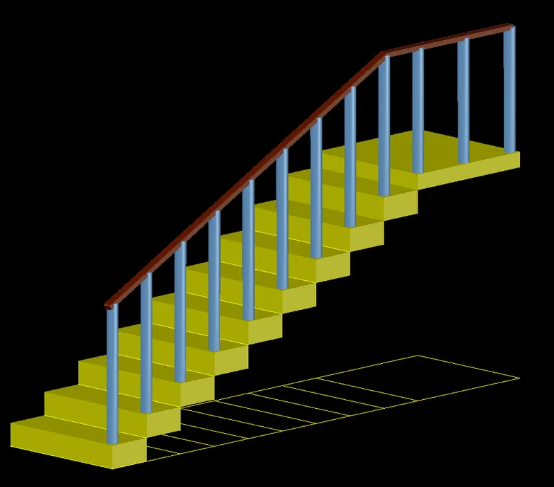
- So we have the follwoing result.
RESULT: -
---------------------------------------------------------X-----------------------------------------------------------------------------
Aim: - To Create the 3D view of a Wall with spread footing given using AutoCAD 3D.
Introduction: - The 3D view of a Wall with spread footing is drawn using proper 3D tools, primarily using the Line tool and after sketching, the dimensions and text are provided. The procedure of drawing is explained in detail with diagrams of each step and the final result is given. The size of the parpaet and the coping is assumed accordingly.
All dimensions are taken in inches.
PROCEDURE: -
Before we start the drawings we need to set up the drawing as Metric and the units into Decimal Units.
Following are the steps in order to set up the drawing as Imperial Template and the units into Engineering Units.
- Go to Application Menu or click CTRL + N (New)
- Click on New from the Application Menu
- A popup menu appears, click on the first tab known as Start from Scratch > Select Metric
- Now click on the third tab known as Use a Wizard > Go to Advance setup > A Dialog box appears > Select the unit of measurement as Decimal > Press Next > select Angle as Decimal Degrees > Press Next > Select Angle Measure > Press Next > Select Angle Direction > Press Next > Select Area > Click Finish
- Set the page limit by entering Limits in the command tab. The lower left corner is specified as 0,0 and the upper right corner is specified as 5000,5000.
- In the Drawing Units dialog box, select 'Decimal' in Type; ' 0 ' in Precision; and 'millimeters' in Insertion scale.
- Click OK
Now,
- Click on the Workspace Switching Tab
- Change the workspace from 2D drafting and annotation to 3D Modelling.
- Now we are all set to go.
Now,
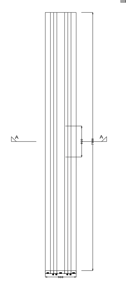
- Draw the plan
- Go to top view and 2-D wireframe.
- Draw 7500 mm vertical line.
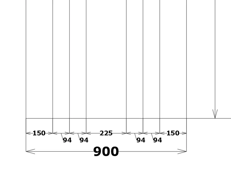
- Take offset of 900 mm thickness for the wall footing.
- Take offset of 150mm of the first vertical line.
- Again take offset of 94 mm thickness for the step footing.
- Again take offset of 94 mm thickness for the step footing.
- Then take 225 mm offset for the thickness of the wall.
- So we have the following drawing.
Now,
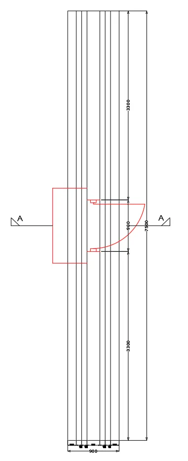
- Draw the door
- Take width as 900mm
- Take the door layer as Red.
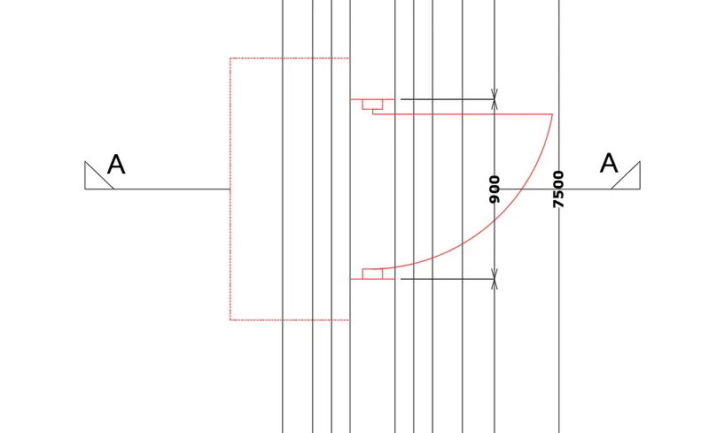
- So we have the follwoing drawing,
Now,
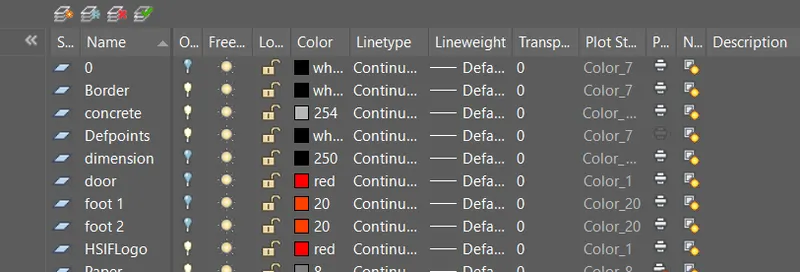
- Before doing the elevation.
- Take some layers.
Now,
- Do the elevation
- Go to SW isometric.
- Draw a rectangle over the plan of dimension 7500 X 900.
- Extrude it to 300 mm height.
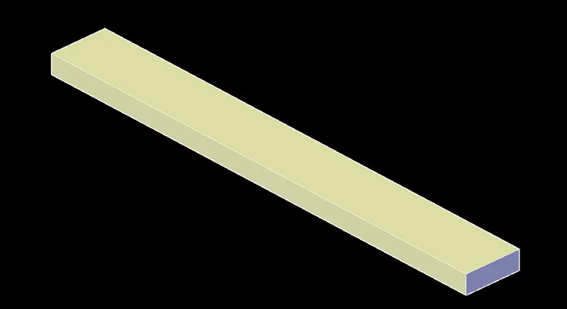
Now,
- Do the 1st step footings elevation
- Draw a rectangle over the plan of dimension 7500 X 601.
- Extrude it to 400 mm height.
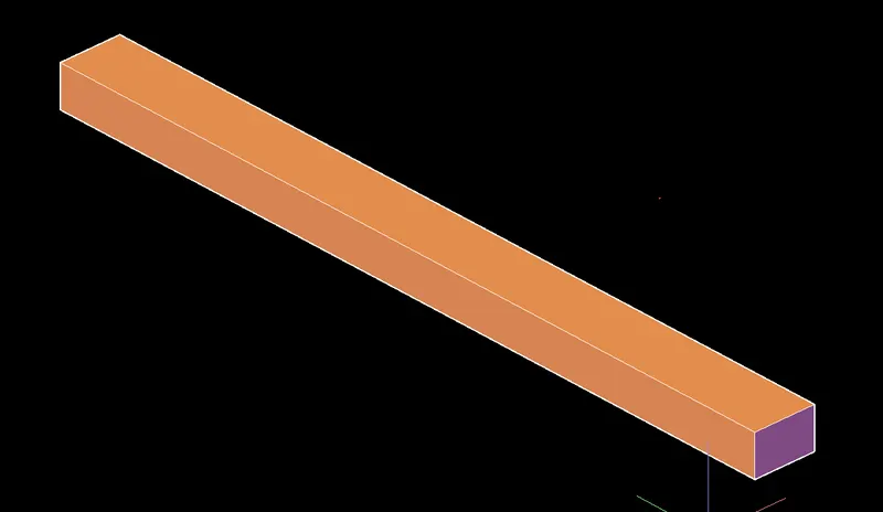
Now,
- Do the 2nd step footings elevation
- Draw a rectangle over the plan of dimension 7500 X 413.
- Extrude it to 400 mm height.
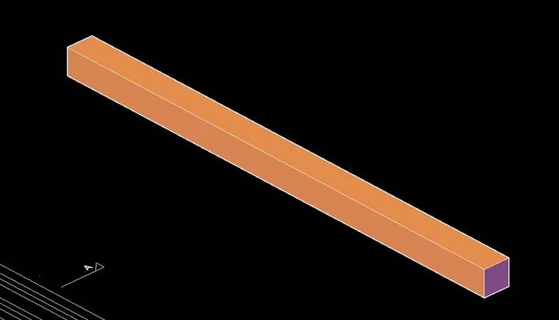
Now,
- Do the wall.
- Draw a rectangle over the plan of dimension 7500 X 225.
- Extrude it to 3900 mm height.
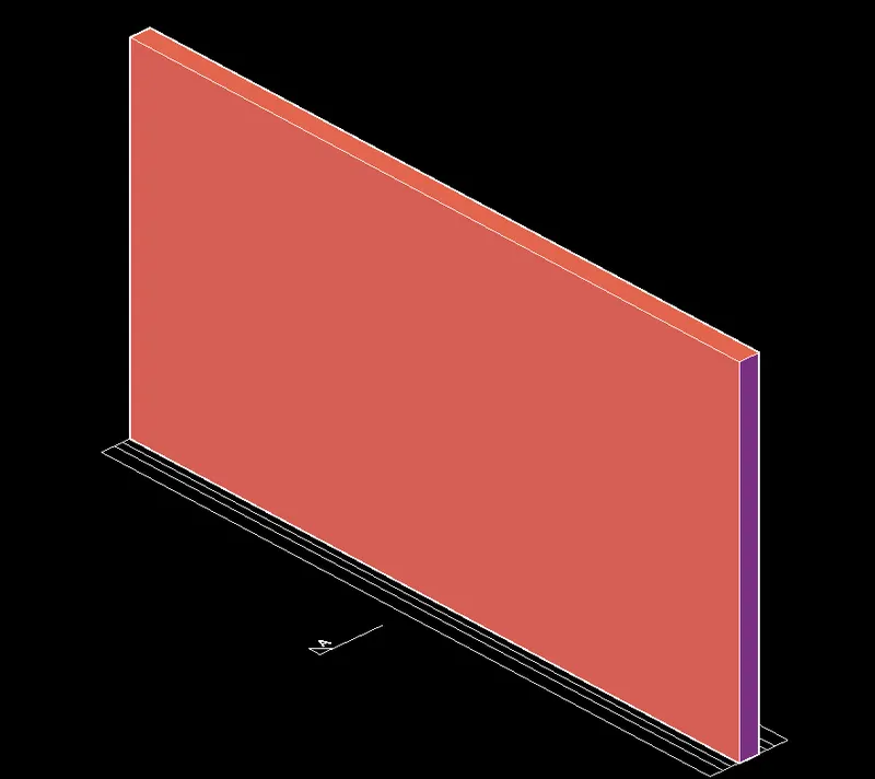
ALL together we have the following drawing.
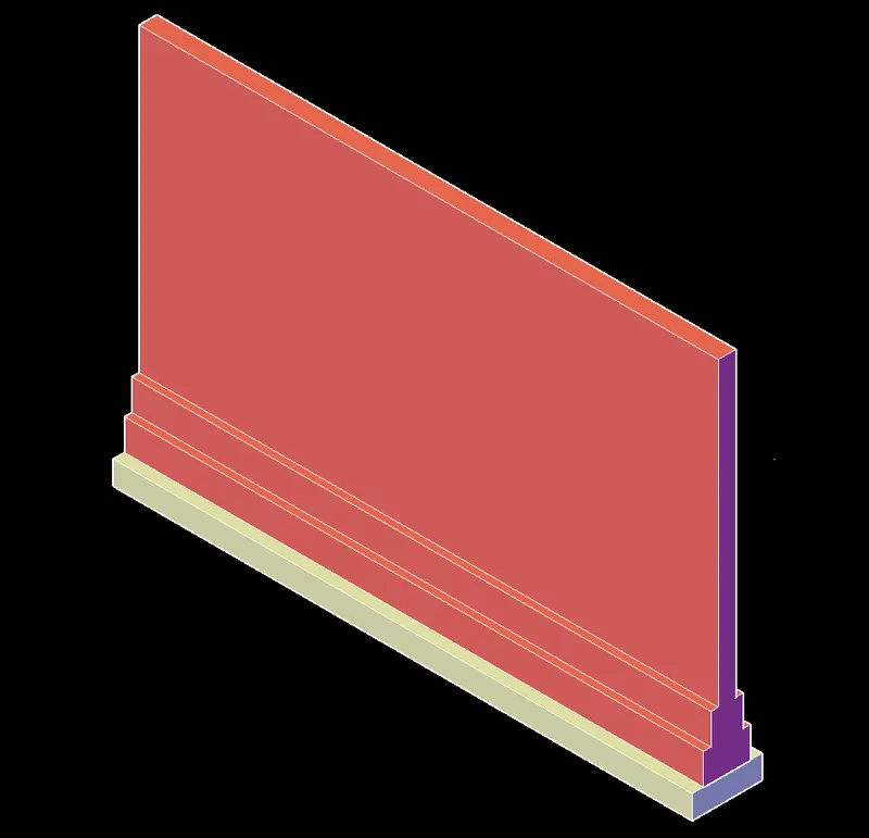
Now,
- Do the door and lintel
- Draw a rectangle over the plan of dimension 225 X 900.
- Extrude it to 2100 mm height.
- Take lintel 100 mm thickness and taper.
Finally, we have the following drawing.
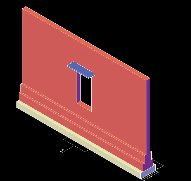
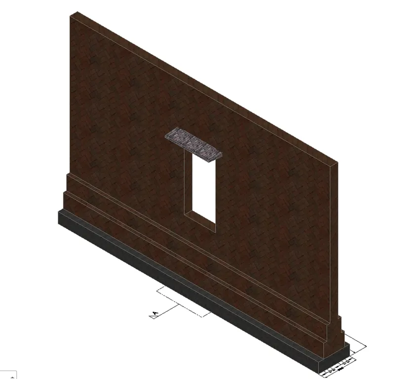
Now, its time for rendering and giving materials to the wall.
- Go to Material Browser
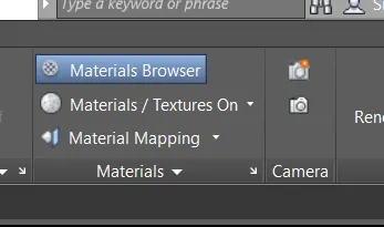
- A popup menu appears
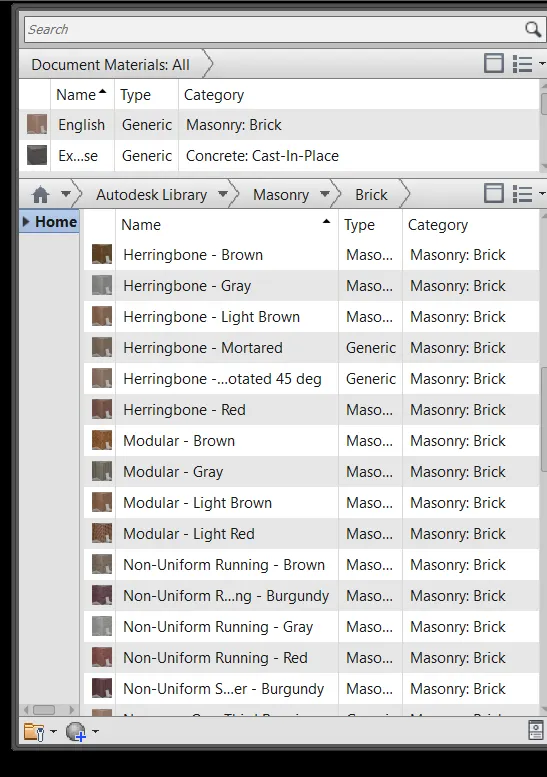
- Give the required materials.
Now,
- Go to visualise tab.
- Go to render panel.
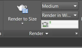
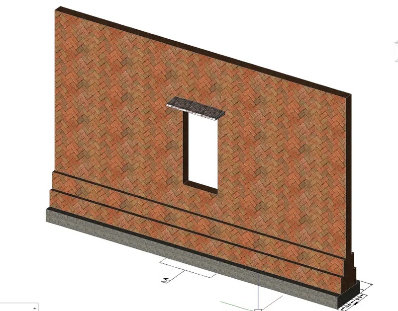
- Type RR for rendering.
RESULT: -
---------------------------------------------------------X-----------------------------------------------------------------------------