Creating 3D Isometric view of various structural elements in AutoCAD
AIM:
(a). Create a 3D Isometric View of the building with plan and elevation given.
(b). Create the 3D View of the Building Façade as given in the plan and elevation. Also, see the detail of the window.
(c). Create the isometric 3d view of a stair with railing as shown in the plan and elevation. Assume the size of the balustrades and the hand rails.
(d). Create the 3D view of a Wall with spread footing. Create the Door opening only. Assume the size of the parapet and the coping. See the plans and elevation for the details. Also, create a rendered view of the model with materials as of your choice
.
INTRODUCTION:
1. Firstly, Define the units and its type with precision requirement of that drawing.
2. Define the origin using UCSICON tab or clicking over the WCS origin and selecting the "MOVE & ALIGN" option.
3. I have defined the sections in the X-Y plane and then further modify it as per the requirement using various commands like "3DROTATE", "3DO", "MOVE", Extrude, Region/Boundary etc.
4. Texting and labelling is done by changing the directional axis and putting the dimensional plane in the X-Y plane.
5. Elevation and sectional views are made by joining the ray lines passing through the vertices cut through the section line.
6. By joining the Ray lines passing through the vertices made by the sectional line, Base line of the elevation plane can be made.
7. After Drawing the base of section/elevation, Sketch the elevation plan in the top view(X-Y plane), followed by 3DROTATE command around the axis of rotation and defining the angle of rotation.
8. After this, Align the Floor plan and elevational plan using the "MOVE" command with a accessible base point defined while allocating.
9. Set the Annotate properties like Lines, Arrows & symbols, Text, Primary units etc.
PROCEDURE:
Figure(a):
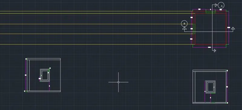
1. Firstly, Draw the Floor plan at the right-hand side of the attached snap above using line, rec, move, copy command etc.
2. After sketching the Floor plan, Cut the floor plan by using section lines named as A-A & B-B.
3. Draw ray lines at the vertices cut by the section line A-A, B-B.
4. Join various ray lines in a cross-section using line command, resulting in base of that section/elevation.
5. After Drawing the base of that section/elevation, Sketch the remaining part of that plan in the Top view (X-Y plane).
6. After Drawing the base made by joining the section line A-A, base is rotated with an angle of -90degree.
7. While the base made by the section line B-B, is drawn without rotation and trimming the ray lines after this base preparation.
8. After drawing the elevation plan in the A-A & B-B, use 3DROTATE command by defining the axis of ori-entation with angle of 90degree.
9. After this, Copy the elevation view and align it with the floor plan at its corresponding points.
10. Create the Region in the floor plan and extrude that part at specified height.
11. Windows are also made in the same way and relocated in the same way as mentioned above.
12. After Extruding the various parts of the structure up to the required height, Windows are fixed at that lo-cation only before proceeding towards greater height.
13. Use the MATERIAL BROWSER option to assign the material properties to various components using VIEW tab.
Final view is attached in the PDF form with name "c-1,13".
FIGURE(b):
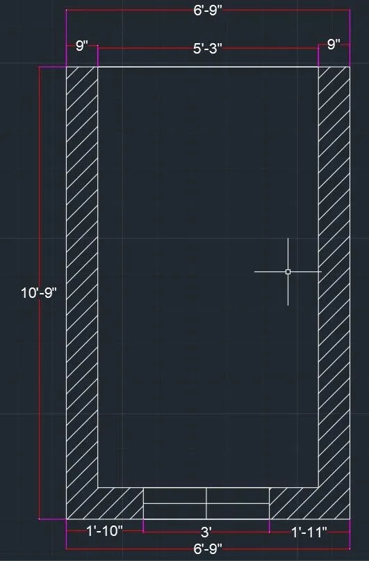
FIGURE(b):
1. Firstly, Draw the floor plan as attached above using the line, rec command etc.
2. Draw the ray lines at the various corners intersect through the section line.
3. Join the rays using line command for setting the elevation base at suitable location from the floor plan in lieu of elevation height.
4. Use line command to join the rays and after base preparation, trim the ray lines.
5. Draw the elevation plan same as the floor plan drawn above.
6. Rotate the Elevation plan in the erection mode using 3DROtate command.
7. Using "MOVE" Command align the elevation plan with floor plan at its corresponding vertices.
8. Define/ Create the regions over the floor plan and then extrude it as per the requirement along the specified height.
9. Follow to complete the accessories of that elevation plan before proceeding further.
10. Use COPY command judiciously three times.
11. After Drawing the sketch, assign the material properties using material browser in the view tab.
12. After assigning the material properties, Plot the Multiview with three view option (above), followed by setting the views by using MS & PS command cautiously.
FIGURE(c):
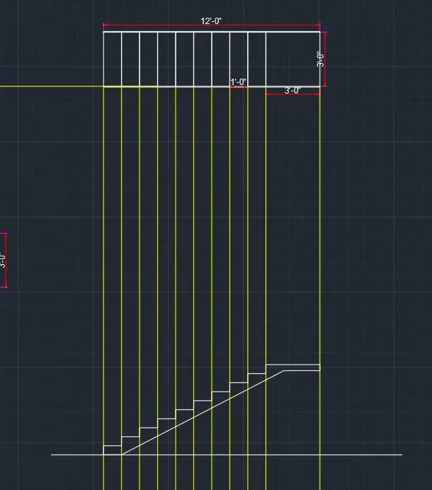
FIGURE(c):
1.Firstly, Draw the Plan view of the stairs shown in the above attached snap in the upper part.
- After sketching the plan, Rays are drawn at the vertices of stringer face of the stair.
- Rays are joined using the line command with thread of 1' and riser of 6" as mentioned at the lower portion in the attached snap above.
- After this, TRIM the ray lines and rotate the elevation plane in the X-Z direction about the X-axis using 3DROTATE command with rotation angle of 90degree.
- After rotating the elevation plan in the X-Z direction, Extrude it along the Y axis with a length of 3.5' inwards.
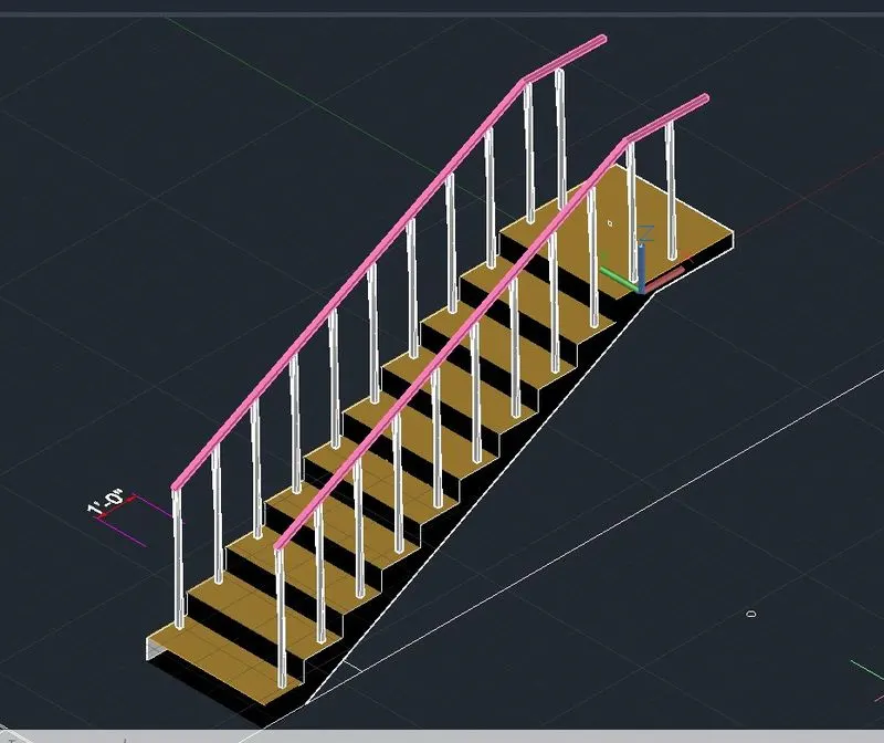
- Hand rails/Balusters are made using rectangular pipe section of dimensions 1"*1".
- Balusters are swept up to a height of 3' with twisting angle of 90degree along its full path.
- Balusters are set at a distance of (2"*5") from the projected cornices of the thread at the corner on either side of a step.
9. Hand rails are extruded along the path governed by the polyline over the balusters.
FIGURE(d):
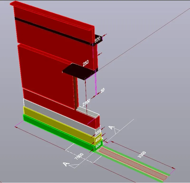
1. Firstly, Draw the plan view of the spread footing with reliable colouring pattern to differentiate between the neighbouring offset in the footing plan.
2. Here three rectangles are drawn with two having the same dimensions of (250 * 3300) and the other one of (250*900) mm.
3. EXPLODE the three above mentioned rectangles and then join the straight lines to create a polyline.
4. select the offset distance of 50mm and select the polyline two times on either side of rectangle while the last line is offset-ed with a distance of 75mm.
5. Hatch the region as mentioned in the attached PDF named under "c-4,13".
6. Cut the Section line with arrows pointing along the direction of observer eye.
7. Draw the RAY lines from the vertices passing through the section line.
8. Draw the elevation plan by sectioning the ray lines using the line command at a suitable distance from the floor plan in lieu of elevation height.
9. After sketching the elevation plan, 3DROTATE this Plan along the X-axis with an angle of 90degree.
10. Using MOVE command, align the floor plan with the elevation plan over the sectional line at its respec-tive coordinates.
11. Create REGION in the elevation plan (X-Z plane) and extrude it in the y direction along specified length measured from the base plan under it.
12. After extruding all the parts of a section, it's better to assign the colour using layer command.
13. For drawing the CHAUKAT/door frame, copy the canopy section of the elevation plan and place it by measuring the floor plan under it.
14. After locating the length of canopy portion by copying the elevated view at the door frame from the eleva-tion plan
at the section line.
15. Extrude the canopy region along the length of copied plan.
16. Draw the cross-section at the base of door frame, swept it along the path traced by a line out skirting along the door opening.
I have drawn this sketch as follows here:
RESULT:
All the sketches are attached here in both forms i.e., PDF as well as JPG form as per convenience of the reader.
Material editing drawings have the problem of invisibility in labelling when printed out in the PDF form so those drawing having such troublesome are taken in the JPG format.