Creating 3D Isometric view of various structural elements in AutoCAD
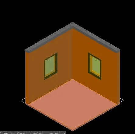
AIM: To Create a 3D Isometric View of the building.
Software that i have used : AUTOCAD
TOOLS that i used:
line
trim
block
dimension
text
rectangle
offset
extrude
subtract
layers
union
presspul.
step by step procedure:
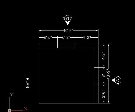
draw a rectangle with dimension 10'9" x 10'9"
xplode it.
take offset draw offset line with distance 9"
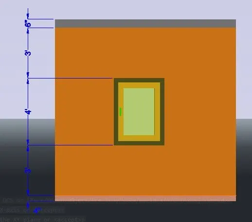
provide the window in the side of the buiding with in the height of 4'.
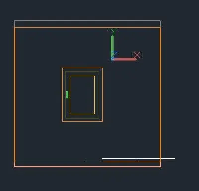
In the elevation there is one window with having 3' length and 4' height.
different layers are create to distinguish the elements .
take layers to their elements .
Take boundary make the wall in to region.
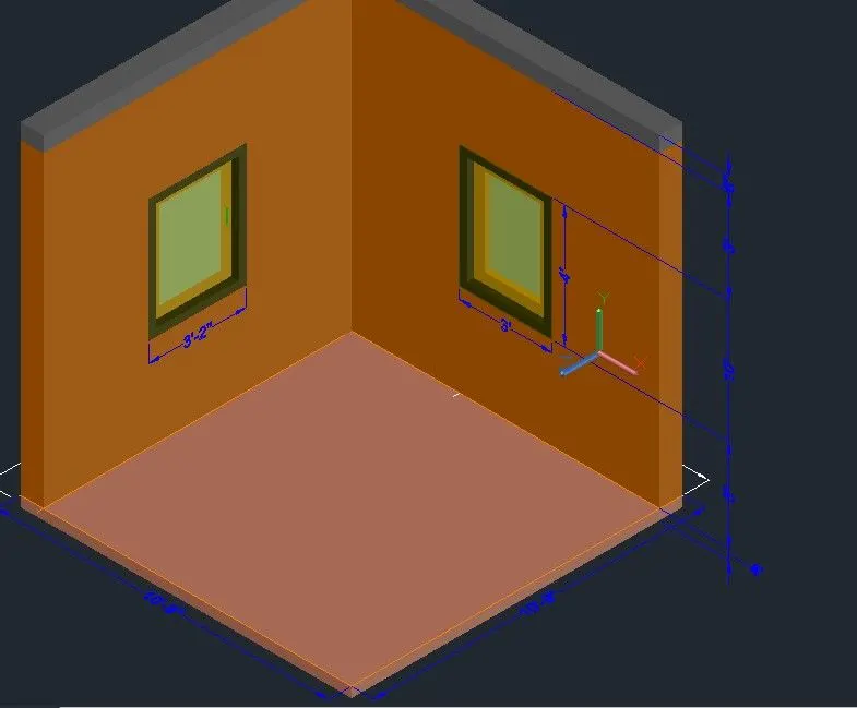
Take extrude tool extrude the wall at height 10'
and extrude the floor with 4" down(z -axis)
provide the space for window .
make the walls union.
with the solidedit command copy the top face of wall. make the slab layer current make in to region.
extrude to 6".
making of window:
take rectangle tool draw rectangle 4'x3'
take offset command provide outer frame width as 3".
inner frame width 4".
assign layers to the window
take region command make each of them surface.
use subtract to remove overlay layers.
extrude as per standard i placed the panel at 4.5 that means median of the wall.
make in to block and insert it open space.
another window with 3'2"x 4' also same procedure has followed.
change the ucs where ever required.
save the ucs position .
go to the ucs manager set in to current.
dimensions are provided to it.
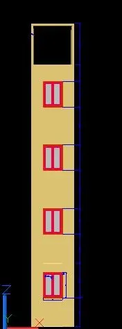
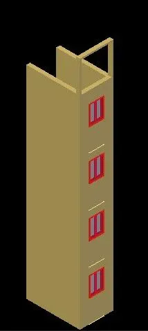
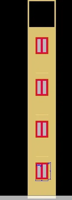
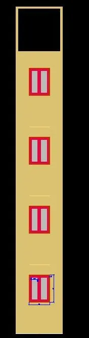
AIM: To Create the 3D View of the Building Façade
line
trim
block
dimension
text
rectangle
offset
extrude
subtract
layers
union
presspul
hatch
step by step procedure:
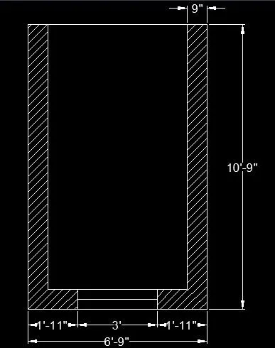
By using rectangle ,explode ,offset made the plan.
provide the hatch and dimensions to it.
create the new layers to distinguish the material make the work easier.
assign the layers to the plan
set the boundaries to the wall make it in to region.
extrude it up to 9'11".
provide the space for window.
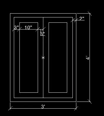
window is made by draw the rectangle with dimensions of 3'x 4'.
offset 2" for outer frame.
offset 3" for inner frame.
provide 10' width for panel.
assign the layers to it.
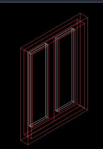
by using region,extrude and subtract finishes the window.
place it in the open space .
make them in to group and copy it paste in the elevation from the 1'5" for above window same procedure is repeated 3 times
make the wall union.
put ucs on the front face. draw a rectangle .
offset 4" trim the unnecessary part and make it int o region.
extrude 9" inside z axis.
provide dimensions to it.
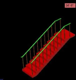
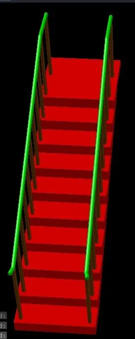
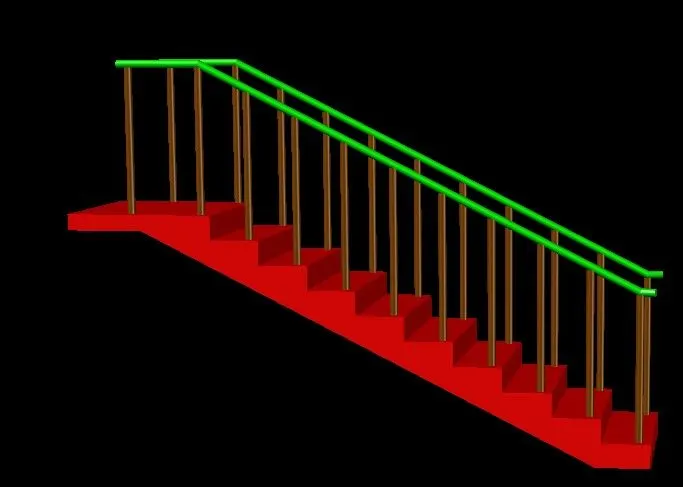
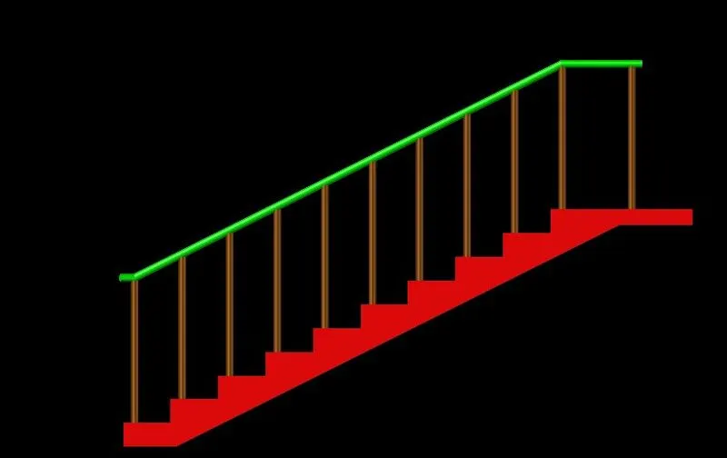
Aim: To Create the ismoteric 3d view of a stair with railing .
line
trim
block
dimension
rectangle
region
offset
extrude
subtract
layers
union
sweep.
step by step procedure
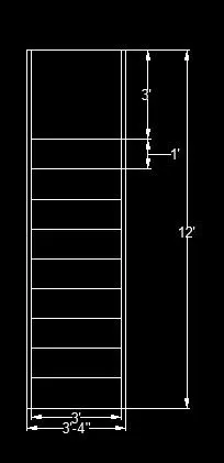
draw the plan with help of rectangle, offset, trim.
provide dimension to it.
draw the step in side view in the plan
9 threads and 10 riser with dimensions of 1',6".
provide waist slab with offset of 6" .
click the home button in the view cube.
make it in to region.
rotate the plan in to 90degree with x -axis reference.
extrude it to the another side with the distance of 3'2".
provide the railings by using circle with diameter 1".
extrude it to 3'2".
with the help of line, circle,region and sweep the balustrade are made.
copy it to another by using mirror command.
it didnot take much time to create this 3d model.
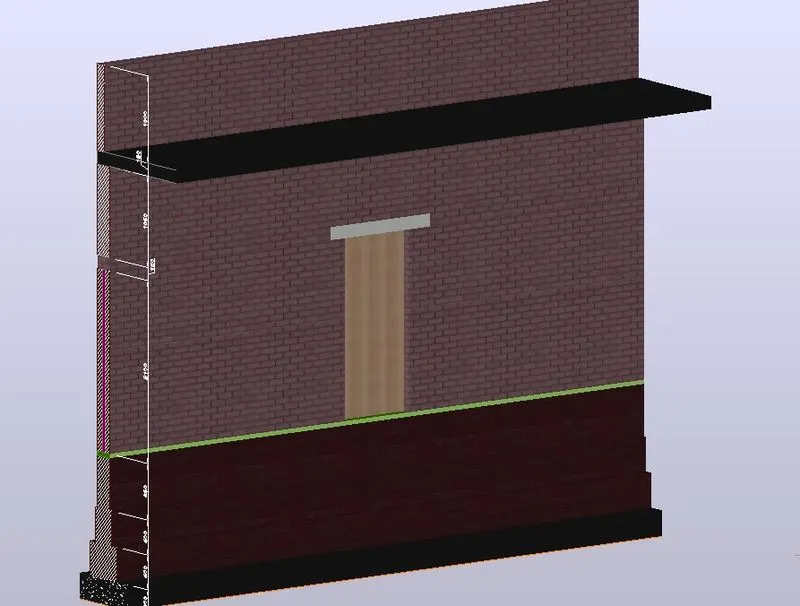
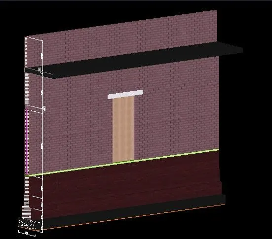
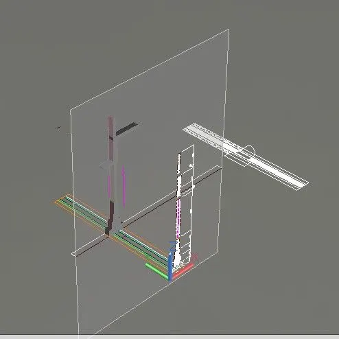
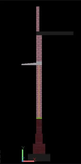
Aim: To Create the 3D view of a Wall with spread footing .
line
trim
block
dimension
rectangle
region
offset
extrude
subtract
layers
union
hatch
region
render
material browser
mapping
section plane.(slice)
step by step procedure:
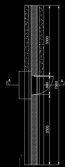
with the help of rectangle, offset,hatch,trim i made the plan.
made the new layers to distinguish the elements.
assign it to the plan.
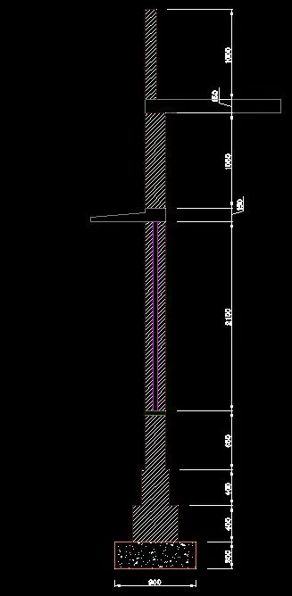
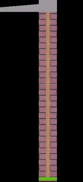
drawn the section with the help of line ,offset,mirror,trim,hatch.
assign the layers to the elemnts.
extrude the section as per the plan
subtract is reuired when placing the door in the middle of the wall.
lintel and door are placed in the middle of the wall.
provide dimensions to it.
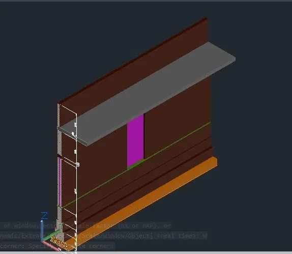
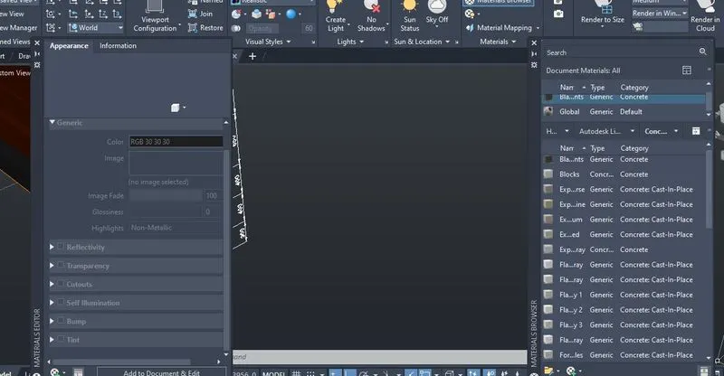
go to visulize tab take the material browser assign some material to our section.
i tried some material according to section.
teak wood is used for the door.
save the some views.
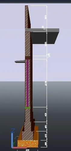
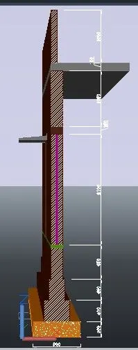
take the section plan i slice the model.now see the section after assigning the material.(x-z direction)
and also used match properties while i assigning the materials .
mapping is done some places.
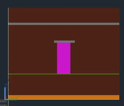
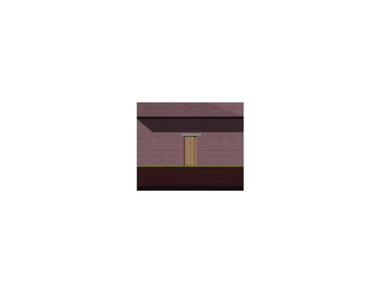
i take render images seen in below
we see the shadow over the door.
Result:
I have Created a 3D Isometric View of the building.
Ihave Created the 3D View of the Building Façade.
I have Created the ismoteric 3d view of a stair with railing .
I have CreateD the 3D view of a Wall with spread footing .