Creating 3D Isometric view of various structural elements in AutoCAD
AIM:- Creating 3D Isometric view of various structural elements in AutoCAD
- Create a 3D Isometric View of the building with plan and elevation given.
stepwise procedure:-
- command or tool used:
- For 2D:
- line
- offset
- trim
- explode
- rec
- move
- copy
- For 3D:
- Boundary
- region
- EXT
- pressfull
- subtract
- union
- move
- 3D rotate........ETC.
- Draw the plan in 2D by use of 2D Drafting and Annotation as shown below diagram/plan drawn.
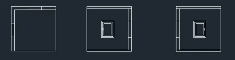
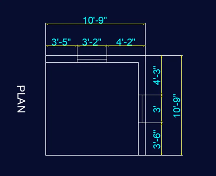
- change the workspace -3D modelling
- set the visual style as conceptual
- set unsaved view as - SE isometric
- take the boundary command
- create the boundary for the wall
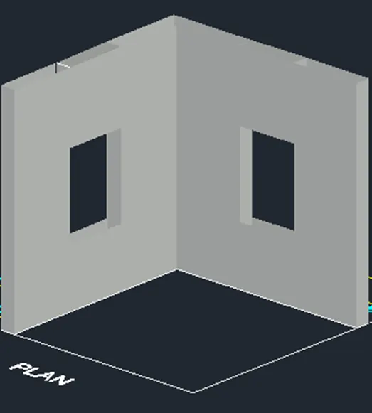
- extrude the wall taking the height as 10'10''
- create the window space in both the wall using Subtract command
- Make the union both the wall
- click on the layer properties
- crate the layers for 3D drawing like 3D wall, 3D window frame, 3D window mullion ..... etc
- take the 3DROTATE command
- select the elevation 1 and 2
- keeping the cursor on the vertical plane and rotate it
- move the elevation parallel to tha plan
- create the windows by use of BO, EXT , SUB, Move command
- place in required position
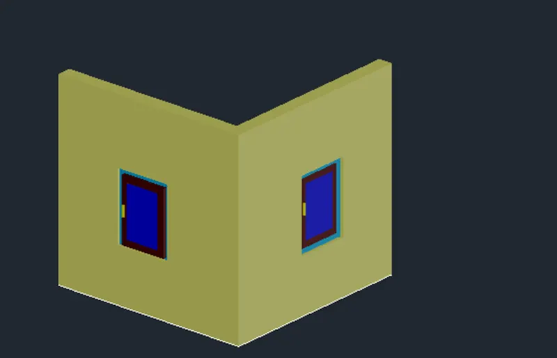
- create the views by orbiting the plan by 3D ORBIT command as below:
- View 1:
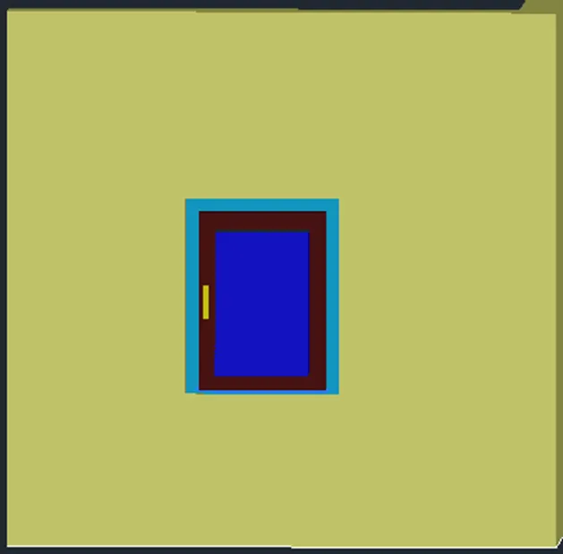
View 2: Elevation A
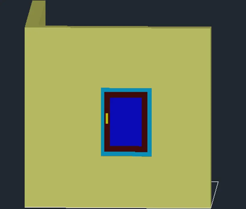
View 3: Elevation B
- Create the 3D View of the Building Façade as given in the plan and elevation. Also, see the detail of the window.
stepwise procedure:-
- command or tool used:
- For 2D:
- line
- offset
- trim
- explode
- rec
- move
- copy
- For 3D:
- Boundary
- region
- EXT
- pressfull
- subtract
- union
- move
- 3D rotate........ETC.
- Draw the plan in 2D by use of 2D Drafting and Annotation as shown below diagram/plan drawn.
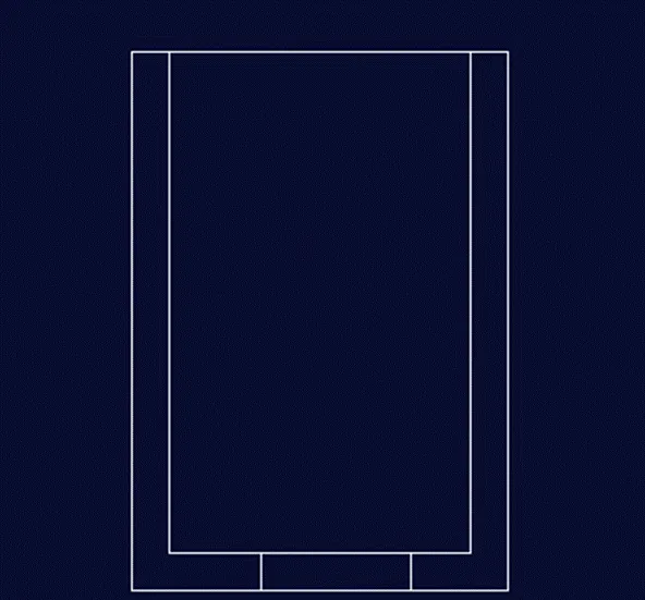
- create the plan for the window
- click the layer properties and create the layers for the window and wall also
- Ext the window frame, mullions, pannels, by keeping the particular layer as set current and with that do subtract simultaniously.
- Keep the workspace in 3D modelling
- keep the SE isometric unsaved view
- keep the visual style as u have
- see the result in below view:
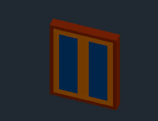
- From the plan of the room
- create the boundary by using the BO command
- set the 3D wall layer as set current
- take EXT command
- extrude the wall at the height of 8'8''
- also do same up to height of 4'6''
- simmilary create the profile of the elevation by using Ext ,pressfull , union command
- copy the window
- select the base point as any corner of the window
- take the copies in particular window opening in the elevation
- see the result as in below view:
- View 1:
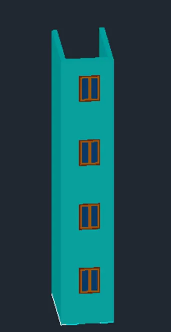
- Take the UCS on the top of the wall
- create the style as see in above view by using rec , 3D poly line, Sweep command
- View 2:
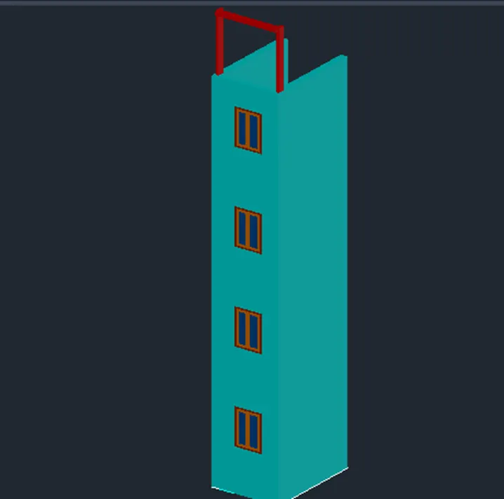
- Create the ismoteric 3d view of a stair with railing as shown in the plan and elevation. Assume the size of the balustrades and the hand rails.
stepwise procedure:-
- command or tool used:
- For 2D:
- line
- offset
- trim
- explode
- rec
- move
- copy
- For 3D:
- Boundary
- region
- EXT
- pressfull
- subtract
- union
- move
- 3D rotate........ETC.
- Draw the plan in 2D by use of 2D Drafting and Annotation as shown below diagram/plan drawn.
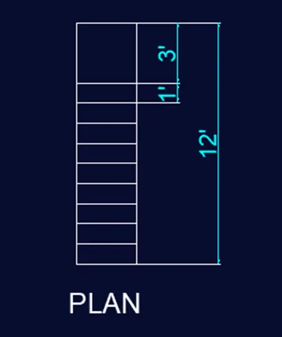
- Keep the workspace in 3D modelling
- keep the SE isometric unsaved view
- keep the visual style as u have
- create the boundary using BO command
- take the EXT command
- extrude the staircase with 3' at inward
- change the visual style to conceptual
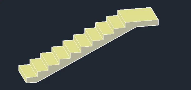
- To draw the baluster and handrail
- take the layer of balusters set current
- take the circle command
- specify the center point on the first tread face
- give the dia as 3''
- offset the circle at 1''
- extrude the inner circle up to 3'2''
- extrude the another one up to height 1'
- move the outer one by 1' upward direction
- copy the baluster and place on the all treads and on landing also
- take the 3p command and draw the line on top of the balusters
- take the circle command
- create the circkle of dia 4'' at any ends of the polyline
- take the sweep command
- select the object as circle
- press enter
- select the path as polyline
- press enter
- then u see the result
- take Rmat command
- give the colour to the hand rail, balusters, to the steps also
- then u see the views as below
- View 1:
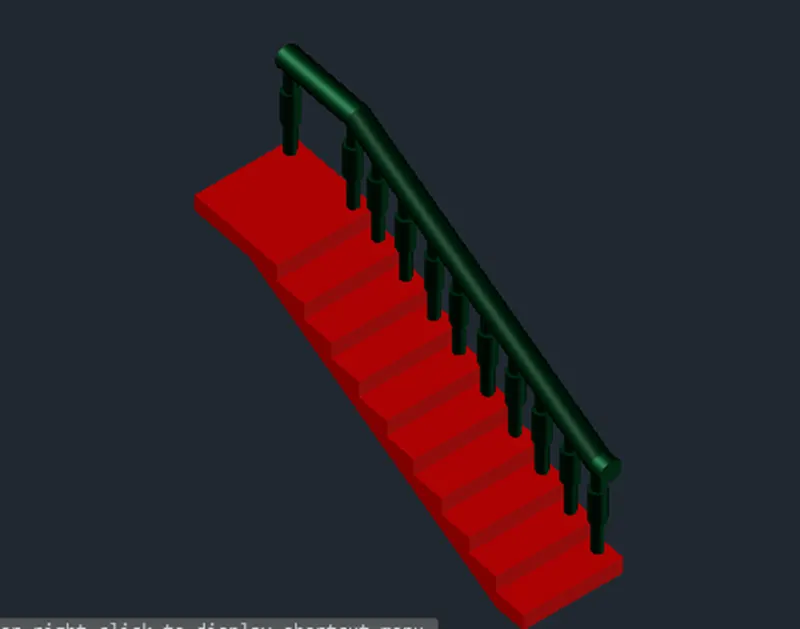
View 2:
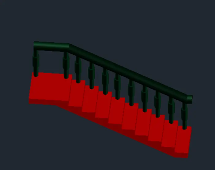
View 3:
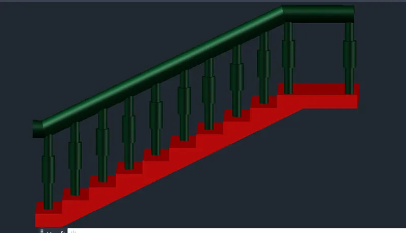
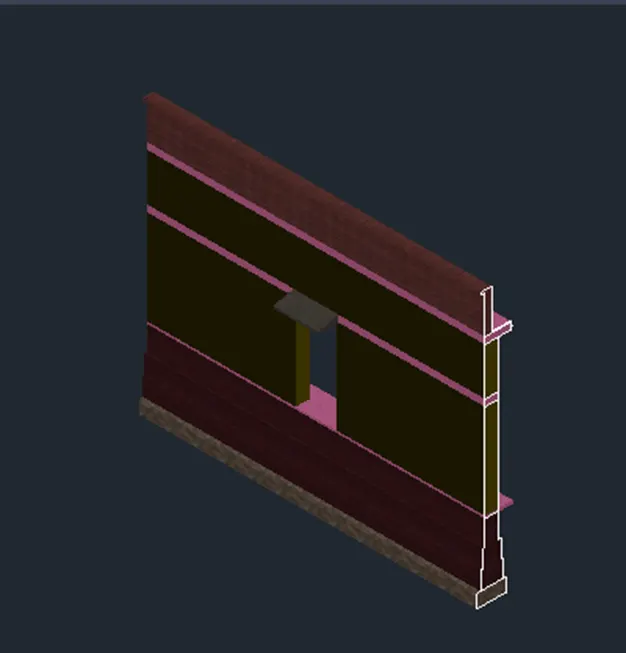
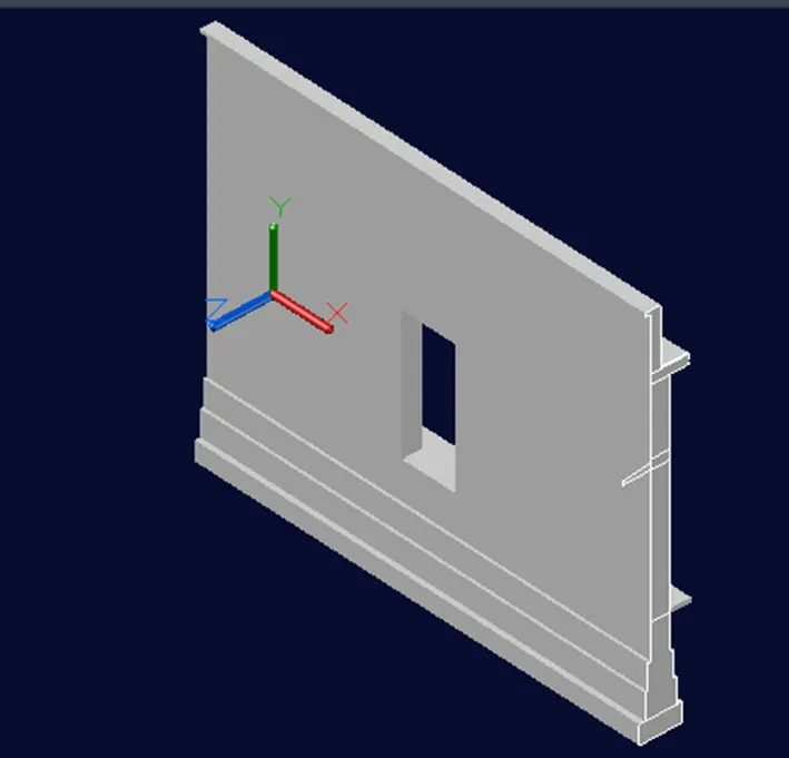
- Create the 3D view of a Wall with spread footing . Create the Door opening only. Assume the size of the parpaet and the coping. See the plans and elevation for the details. Also, create a rendered view of the model with materials as of your choice.
stepwise procedure:-
- command or tool used:
- For 2D:
- line
- offset
- trim
- explode
- rec
- move
- copy
- For 3D:
- Boundary
- region
- EXT
- pressfull
- subtract
- union
- move
- 3D rotate........ETC.
- Draw the plan in 2D by use of 2D Drafting and Annotation as shown below diagram/plan drawn.
- give the dimensions proper
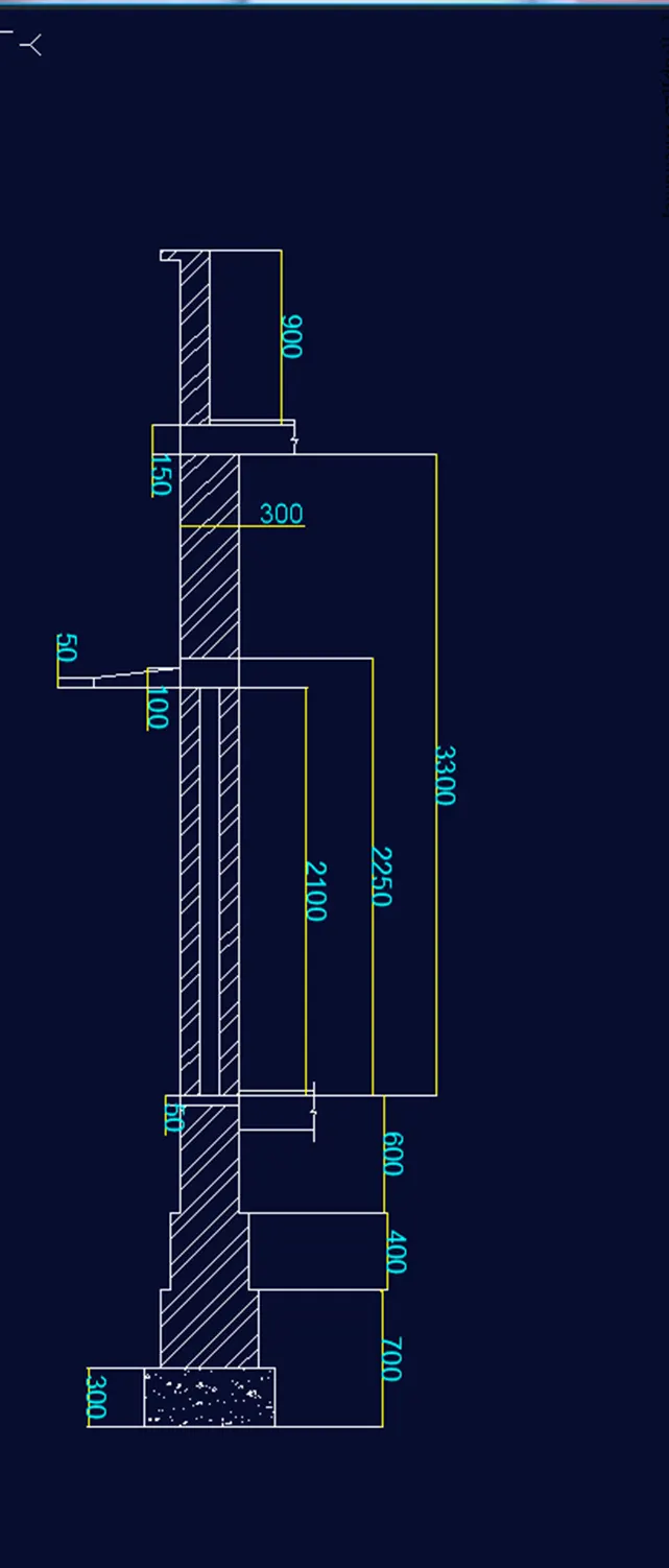
- set the workspace in 3D modelling
- set the unsaved view as u want
- i have the SE isometric
- create the region by using the region or BO command
- take 3D rotate command
- select the object
- select the red one and take the angle 90
- take the EXT command
- select the region press enter
- keep the curcor on backside of the object and taje 7500 mm distance as have in the plan of question figure
- To create the penning of the door
- take the ucs on the wall face
- create the rec of 900mmx2100mm
- move on the required place that u have
- estrude this door
- subtract it from the wall
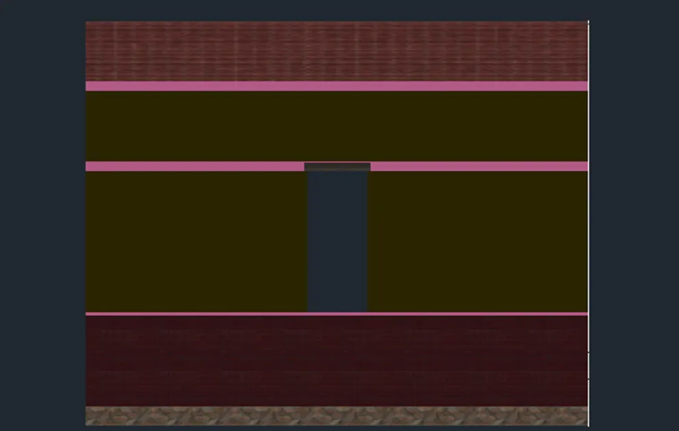
- Take the Rmat command
- and give the particular materials as u have to like to see more asthetic
- see the results in the below views
- View 1:
View 2: