Creating 3D Isometric view of various structural elements in AutoCAD
Week 12-Assignment 12-Module 2
Aim: To create a 3D Isometric Views of various Structural Elements in AutoCAD.
Introduction: For these exercises, this is just a matter of applications of what have been covered from week 12 titled Getting Started with 3D Modeling. Below are the topics covered from week 11;
- Solid View, this tool creates orthographic views, layers, and layout viewports automatically for 3D solids. Click the Solid View tool. The program switches to a paper space layout and prompts you to enter an option. There are four options: UCS, Ortho, Auxiliary, and Section.
- 3D Orbit, this command makes the object be viewed in three dimensions, and the direction of view may be rotated in real-time just like the ZOOM and PAN commands. The orbiting features combined with the surface modeling routines are very powerful tools in terrain design.
- Solid Edit, this is an editing tool command for any 3D object created. It covers the many editing options for solid face, edge and body of a 3D objects
- Fillet Edges, this is a sharp-edge-breaking feature that specifically adds a radius, either concave or convex, to the interior corner of a part.
- Chamfer Edges, this a function that makes a transitional edge between two adjoining right-angled faces of an object.
- 3D Rotate Option, this will make you easily rotate an object from the plane x,y to x,z or to y,z or vice versa.
- Mirroring 3D Object, this command allows objects to be mirrored about selected points or about any of the three X-Y-Z planes.
- Rotating 3D Object, this ROTATE3D command is used to rotate objects in 3D space around an axis or two XY points.
- Moving 3D Object, 3Dmove command is to move the object a determined distance following to a determined direction. When you choose base point, a move grip tool following to 3D view appears.
- Arraying a 3D Object, same with the 2D array it creates/ duplicates object in rectangular or polar type in 3D dimensions.
- Align 3D Objects, the 3DALIGN command to specify up to three points to define the source plane followed by up to three points to define the destination plane. The first source point on an object, called the base point, is always moved to the first destination point.
Procedure:
A. Setting the Drawing Parameters;
- Set up the measurement units according to sketched information provided.
- In the status bar, click workspace switching icon and select 3D basics or 3D modeling to enable workspace capable of working on 3d models with the appropriate 3D tools.
B. Starting the exercise;
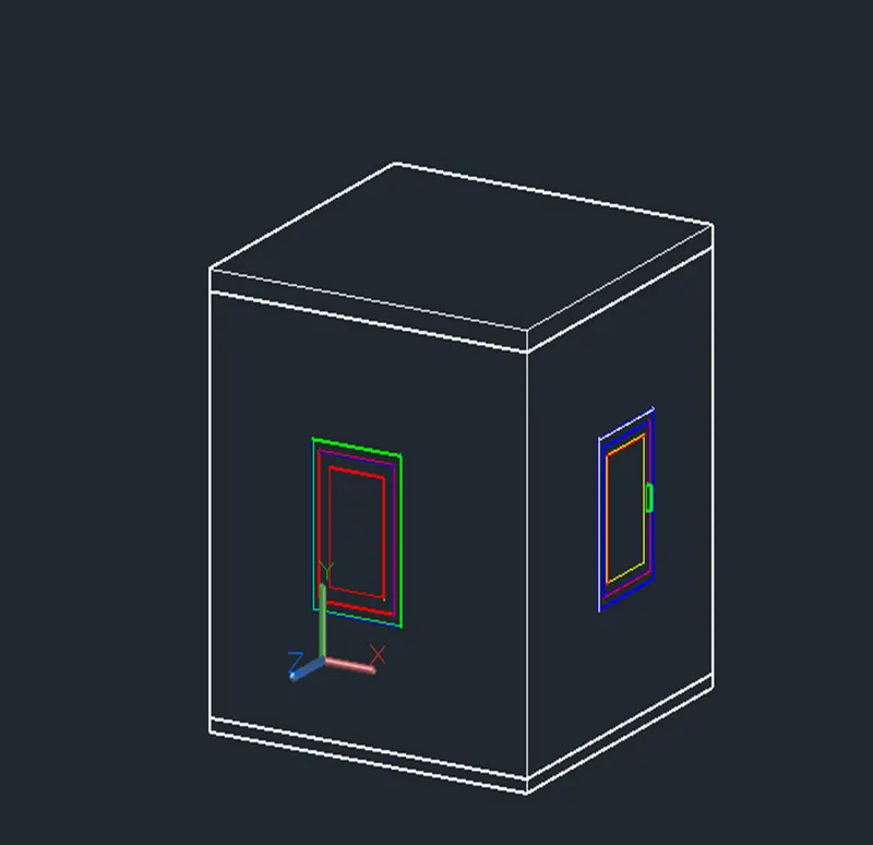
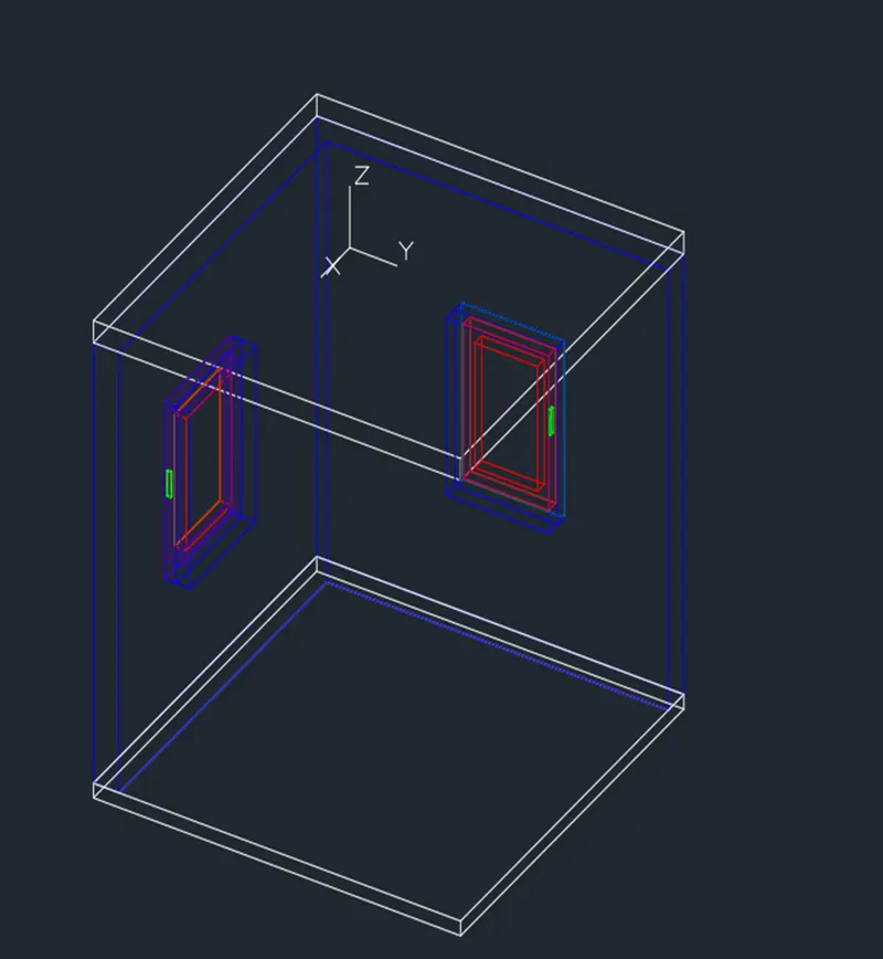
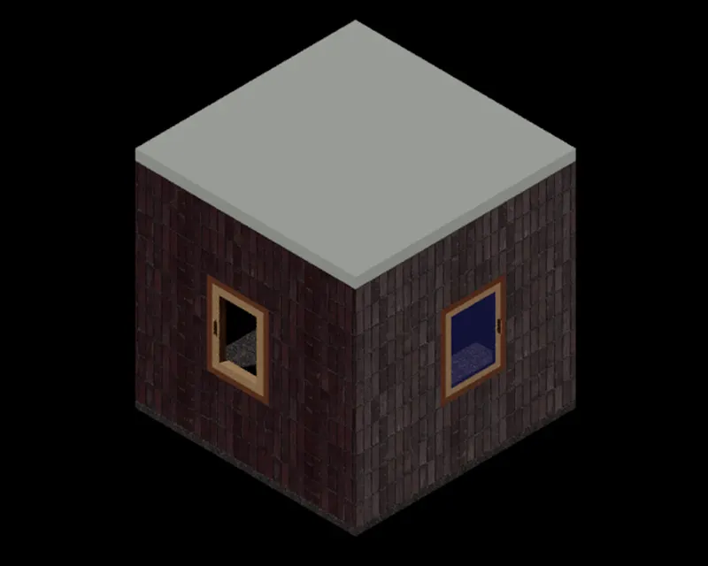
- Combination and manipulation of all the different coordinate entry methods, drawing and modifying tools learned from weeks 1 to 12 were being used here in the completion of all the exercises given and result as pasted below.
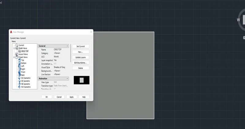
- I have attached some screenshots while working on the exercises to show the procedure on how it was done to come out with the requested plot layouts.
C. Challenge;
- In general, below commands/functions were being used while working on the exercises.
- Units
- LIMMAX
- DDIM
- LINE
- OFFSET
- MLINE
- TRIM
- ERASE
- EXTEND
- DIM
- COPY
- POL
- REC
- JOIN
- C
- UCS
- EXTRUDE
- SWEEP
- LOFT
- UNION
- PRESSPULL
- REGION
- BOUNDARY
- VISUAL STYLES
- RENDER
- CAMERA
- MATERIALS BROWSER
- VPORTS
- SUBTRACT
- MATCHPROP
- 3DALIGN
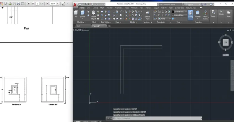
Challenge 1: Below are the brief steps while working on the 3D Isometric View of the Building with Plan and Elevation given;
- On the Top View, draw the section using the ML command with two parallel lines of 9” spacing following the geometries given from the Plan.
- Closed the boundary by drawing a line to both ends.
- Proceed with the region command.
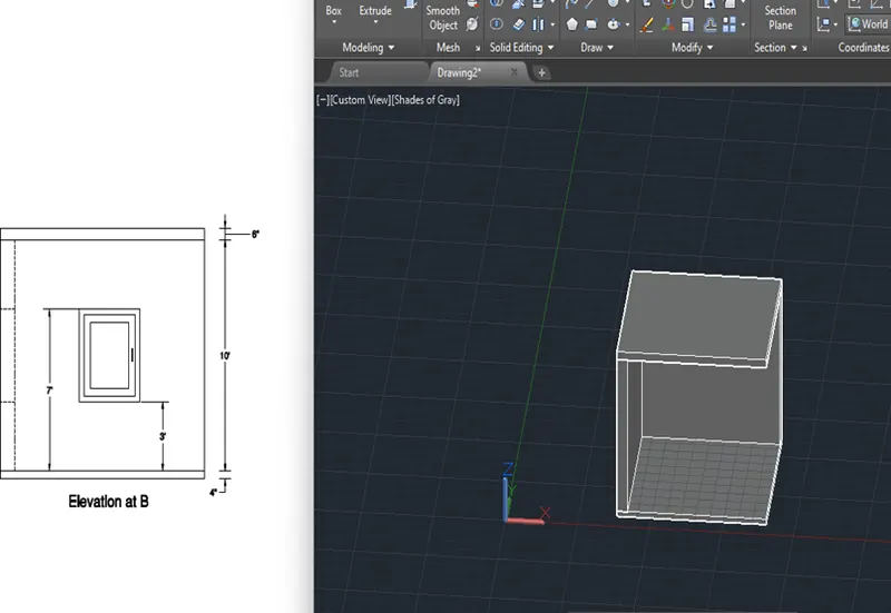
- Extrude the created surface into a solid one at a height of 10’ taken from the Elevation A and B given figures.
- Back to Top View, draw a rectangle following plan view dimension and create a region out of it. You may extrude it for 6”.
- Copy the created solid triangle on the opposite end/ bottom of the created wall. Use the presspull function and reduce the 6” by 2” to make it 4” as the base floor of you created wall while the 6” will be the upper portion.
- Now proceed creation of the Window following the given dimensions out of rectangle, offset, trim, erase, boundary and subtract commands.
- Make a projection of the window using extrude on an assumed height just to project a 3D window. Work on subtract and repeat extrusion as needed or applicable.
- Create the window by manipulation of UCS orientation to the wall created and draw a temporary lines to position the opening. Ensure proper given dimensions are followed.
- Openings will be created out of solid rectangle and subtract to the wall.
- Move or copy the created window to its location. You may also use 3DALGN command if not in the same plane with the walls.
- Position the completed 3D figure to its desirable view and proceed with the material assignment as applicable.
- Render the isometric view.
Challenge 2: Below are the brief steps while working on the 3D View of the Building Façade with Plan, Elevation and window detail given;
- On the Top View, draw the section using the ML command with two parallel lines of 9” spacing following the geometries given from the Plan.
- Closed the boundary by drawing a line to both ends.
- Proceed with the region command.
- Extrude the created surface into a solid one at a height following the Elevation given.
- Go to Front View, and proceed creation of the 2 Window following the given dimensions out of rectangle, offset, trim, erase, boundary and subtract commands. Take note that two types of windows as per the elevation details despite of common window detail. One window height is 4’ while the other is 4’2”.
- Make a projection of the window using extrude on an assumed height just to project a 3D window. Work on subtract and repeat extrusion as needed or applicable.
- Create the window by manipulation of UCS orientation to the wall created and draw a temporary lines to position the opening. Ensure proper given dimensions are followed.
- Openings will be created out of solid rectangle and subtract to the wall. Openings can be done at front view creation of temporary lines following the elevation details.
- Move or copy the created window to its location.
- From the same Front View, you may proceed creation of the top portion object out of ML command following the geometries and dimensions given. Convert it to solid same as in previous steps. You may extrude it by “9” following Section A detail.
- Position the completed 3D figure to its desirable isometric view and proceed with the material assignment as applicable and if requires.
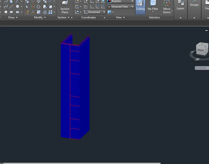
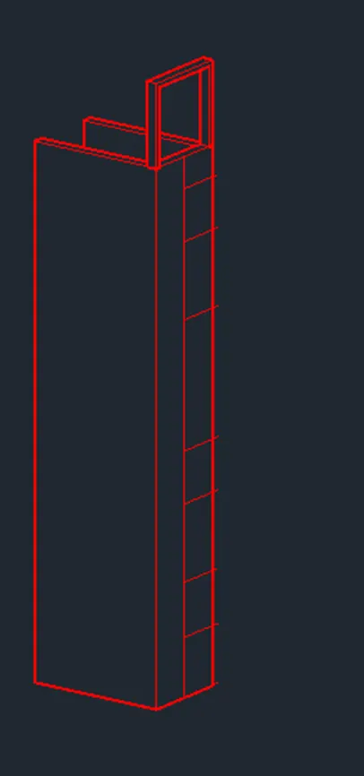
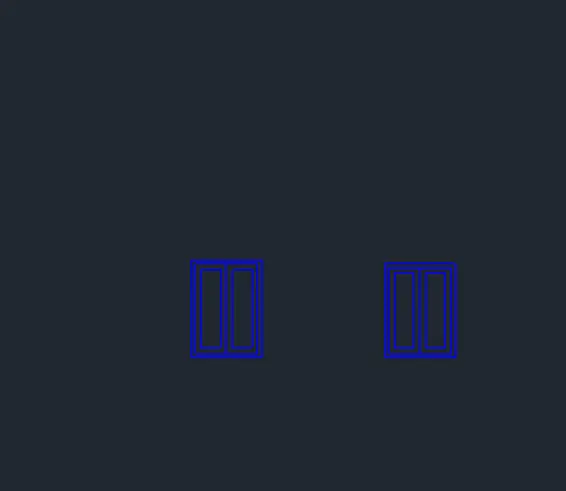
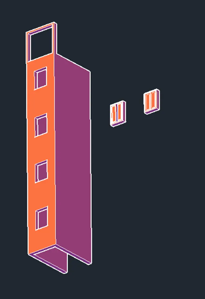
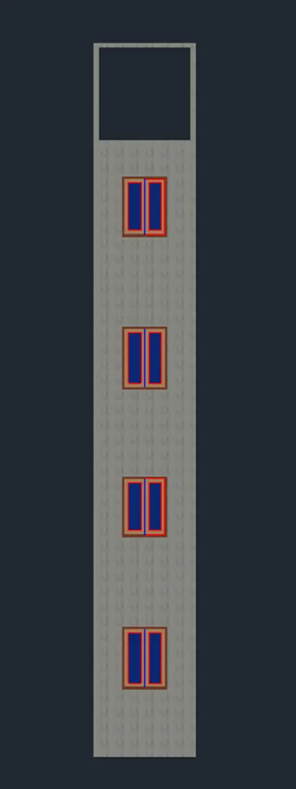
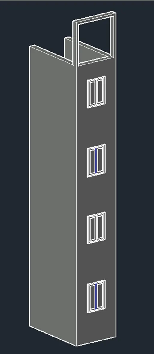
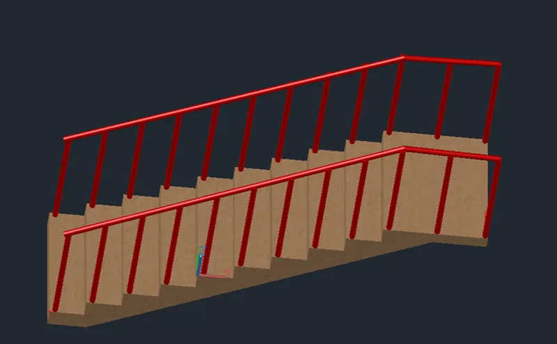
Challenge 3: Below are the brief steps while working on the 3D Isometric View of a Stair with Railing as shown in the Plan and Side Elevation with assumed sizes of Balustrades and Hand Rails;
- On the Top View, draw the section using the L or PL command following the dimensions given for the riser and thread. You may use also fillet, trim, offset and erase commands as applicable.
- Proceed with the region command once staircase section is done.
- Extrude the created surface into a solid one at an assumed height of 1.2m or 3.936’.
- Create the Balustrade by manipulation of UCS orientation to the staircase created and draw a vertical line following the dimension give.
- Now create a circle on a proper plan with a diameter of 2” as assumed.
- Using the sweep command with the vertical line as path, the balustrade can now be created out of the 2’dia. Circle (which was also actioned region command before the sweep).
- You may copy the balustrade to all the threads on one side of the stairs following the positioning from the Side Elevation and Plan given.
- Proceed with the handrail as similar type of method as what was done for the balustrade but this time your line (path) should be connected on the top of the balustrades.
- You may union then all the balustrades and handrail.
- Mirror the Balustrades and Handrail on the other side of the stairs using the staircase midpoints as the axis.
- Move or copy the created window to its location.
- Position the completed 3D figure to its desirable isometric view and proceed with the material assignment as applicable and if requires.
- You may Render the view.
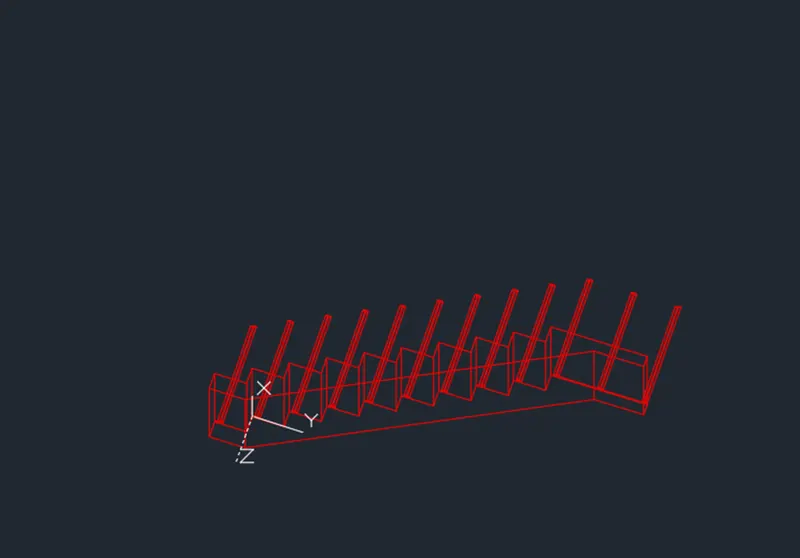
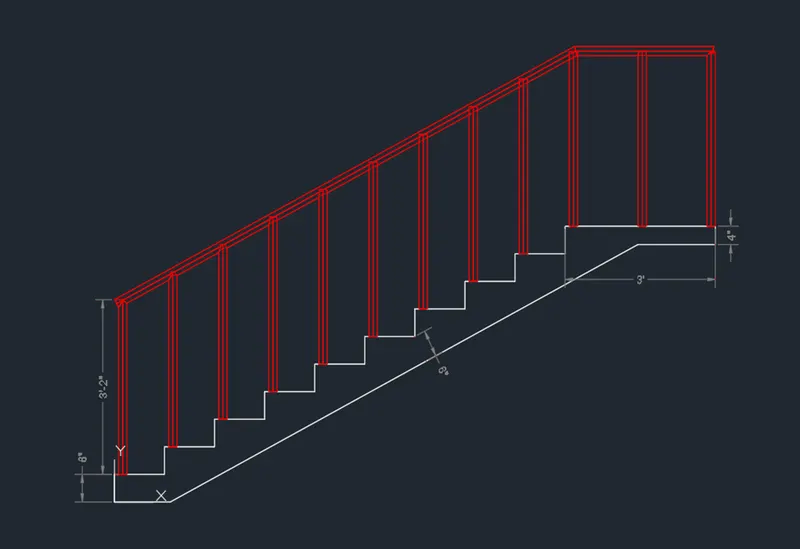
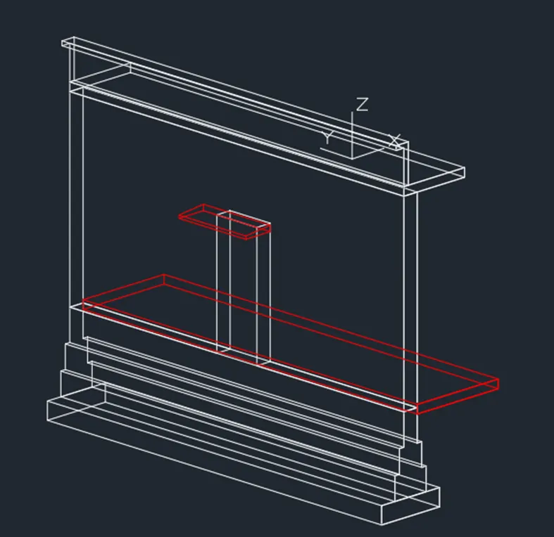
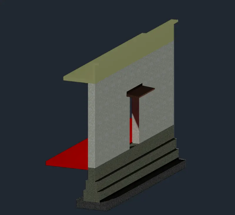
Challenge 4: Below are the brief steps while working on the 3D View of a Wall with Spread Footing and Door Opening with assumed sizes of Parapet and Coping using the given Plan and Section Details;
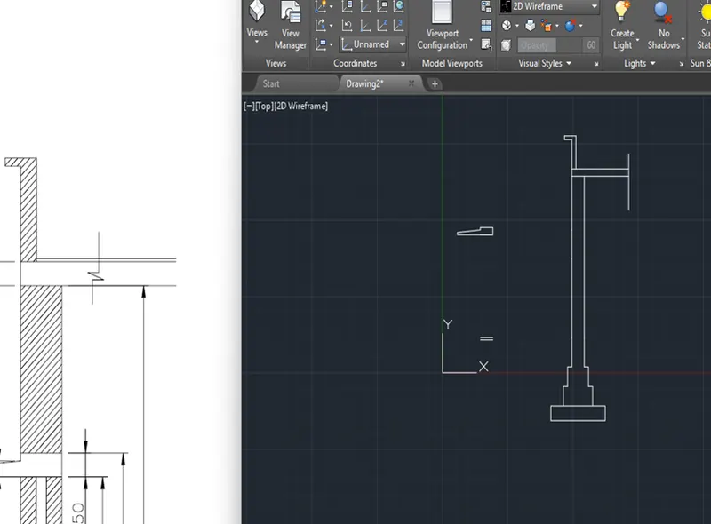
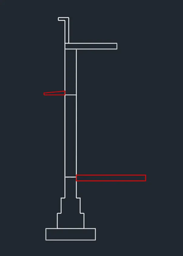
- On the Top View, draw the section using the L or PL command following the dimensions given. You may use also fillet, trim, offset and erase commands as applicable.
- Proceed with the boundary command.
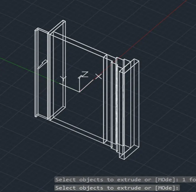
- Extrude the created surfaces at a height of 7500mm.
- Door Opening will be created out of solid rectangle and subtract to the wall. Openings can be done proper positioning of the UCS and following the given dimensions.
- Proceed with shade on top of the door opening following the dimensions given. This can be done by making the section, do the region or boundary, extrude (assumed height) and move to its proper location with the aid of proper UCS positioning.
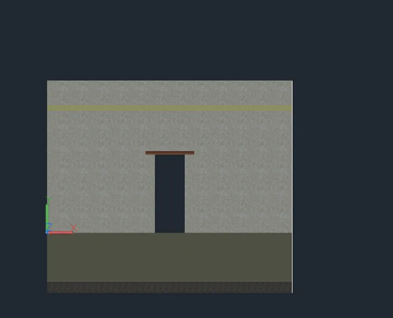
- Position the completed 3D figure to its desirable isometric view and proceed with the material assignment as applicable and if requires.
- You may Render the view.