Creating 3D Isometric view of various structural elements in AutoCAD
Question no.1:
- AIM:
- To reate a 3D Isometric View of the building
- To use proper view.
- Procedure:
- Open a new Autocadd file.
- Set the workplane in 3d view through workplan customization.
- The drawing to be drawn is 3D Isometric View of the building
- The 3D isometric view of the building is drawn using the plan view of the walls of the building.
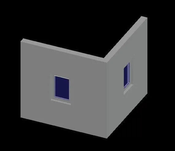
- Here in this sketch the plan consist of two walls containg windowns in each wall.
- The two windows in each wall is of different dimensions.
- To sketch the 3d view of this plan.
- First the plan view of the building is sketched on a 2D plane.
- The provsions for the windows in the plan is given as a gap with required dimensions.
- Then the remaianing part of the wall drawn as 2D is made as region.
- And then the region is extruded to 10' heigh.
- Then the gap provisions left for the window is to be viewed in 2D plane.
- And then a rectangle of the respctive gap sizes are drawn.
- then the rectangle is extruded to a height of 3' as the sill height of thye window.
- Then the edge extraction is used to extract the top face of the rectangle.
- Then the extracted face is moved to a height of 4' as the height of the windoe.
- Then the extrected face is extruded for a height to the end of the wall as the head height of the window.
- Now the window is sketched separately.
- The panel width of the window is 3" and the inner panel is of 4".
- Then the remaianing space is made as glass.
- The respective materials were applied for the panels and the glass.
- Then the windows were fitted into the wall.
- Then the view of the wall in 3d such that to see both windows and the walls are placed.
- Thus the required 3D Isometric View of the building is sketched.
- RESULT:
- Thus the required 3D Isometric View of the building is sketched.
- Proper dimensions are used.
- The tools that are suitable for the 3dworkplane were used.
Question no.2:
- AIM:
- To create the 3D View of the Building Façade
- To use proper view.
- Procedure:
- Open a new Autocadd file.
- Set the workplane in 3d view through workplan customization.
- The drawing to be drawn is 3D View of the Building Facade
- The 3D isometric view of the building facad is drawn using the plan view of the walls of the building.
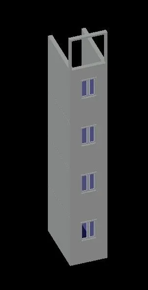
- Here in this sketch the plan consist of three walls containg a window.
- To sketch the 3d view of this plan.
- First the plan view of the building is sketched on a 2D plane.
- The provsions for the window in the plan is given as a gap with required dimensions.
- Then the remaianing part of the wall drawn as 2D is made as region.
- And then the region is extruded to required height
- Then the gap provisions left for the window is to be viewed in 2D plane.
- And then a rectangle of the respctive gap sizes are drawn.
- then the rectangle is extruded to a height of 4'6" as the sill height of thye window.
- Then the edge extraction is used to extract the top face of the rectangle.
- Then the extracted face is moved to a height of 4'2" as the height of the windoe.
- Then the extrected face is extruded for a height to the end of the wall as the head height of the window.
- Now the window is sketched separately.
- The panel width of the window is 2" and the inner panel is of 3".
- Then the 11" space is made as glass.
- The respective materials were applied for the panels and the glass.
- Then the windows were fitted into the wall.
- Then the wall along with the window is copied 4 times such that it matches the requirement the facad of the building.
- Then on the top a elevation is set with a 4" thickness and 9" length.
- The elevation is extruded to a height of 6'5".
- Then the view of the wall in 3d such that to see both windows and the walls are placed.
- Thus the required 3D View of the Building Façade is sketched.
- RESULT:
- Thus the required 3D View of the Building Façade is sketched.
- Proper dimensions are used.
- The tools that are suitable for the 3dworkplane were used.
Question no.3:
- AIM:
- To create the ismoteric 3d view of a stair with railing
- To use proper view.
- Procedure:
- Open a new Autocadd file.
- Set the workplane in 3d view through workplan customization.
- The drawing to be drawn is ismoteric 3d view of a stair with railing
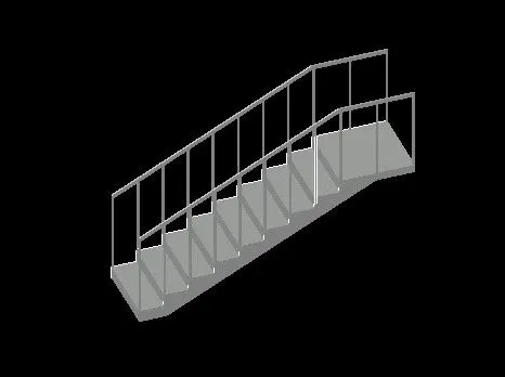
- The ismoteric 3d view of a stair with railing is drawn using the plan view of the stair.
- Here in this sketch consist of the plan of the stair.
- The stair thread is given as 1' and then the total length of the stair along with the landing is given as 12'.
- hence the riser of the stair is assumed as 6".
- Then the riser and the thread of the stair is sketched as 2d object as a side view of the stair.
- The waist beam is also sktched along with the thread and riser as a width of 6".
- Then the 2d sketch is amde as region.
- then the region is extruded for a 3' as a standard stair width.
- Then the railing on the stair is to be sketched.
- The railing widtha dn the length is considered as square and considered as 1"x1"
- Then the top railing rum is sketched eih 2"x 2" dimension.
- Then the run is attached to teh railing grill.
- Then theb grill is copied in equal spacing to required positions.
- Then the stair is viewd in the required 3d view.
- Thus the required ismoteric 3d view of a stair with railing is sketched
- RESULT:
- Thus the required ismoteric 3d view of a stair with railing is sketched
- Proper dimensions are used.
- The tools that are suitable for the 3dworkplane were used.
Question no.4:
- AIM:
- To create the 3D view of a Wall with spread footing
- To create a rendered view of the model with materials
- To use proper view.
- Procedure:
- Open a new Autocadd file.
- Set the workplane in 3d view through workplan customization.
- The drawing to be drawn is the 3D view of a Wall with spread footing
- The 3D view of a Wall with spread footing is drawn using the plan view of the wall.
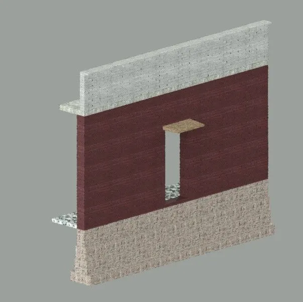
- Here in this sketch consist of the plan of the wall along with a door opening in it.
- Initially the plan of the wall is sketched with specified dimesions./
- The wall si sketched as 2d and then it is extruded to the said height.
- Then the door opening is left as a opening without dooe.
- The door has a sunshade .
- The sunshade is sketched with the required shape and dimension.
- Then the wall is attached to two floors on the top and the bottom.\
- Below the bottom floor the footing of the wall begins.
- The footing is spread footing in this case.
- The spread footing is sketched in 2d firs in the requird shape.
- And then it is extruded to the required length.
- Then the above floor has a parapet wall above the wall drawn.
- The parapet wall is drawn as 3' height wall.
- Then the material is applied to component.
- And then the rendering procedure is followed.
- The camera is set in the required position.
- Then the light setting is set.
- Here we used a distant light such that it looks like a light from the sunlight.
- Then the rendering is done.
- The renderd model is placed.
- Thus created model is shown below.
- RESULT:
- Thus the 3D view of a Wall with spread footing is created successfully.
- Required materials were applied.
- The rendering is a proper view was done.
- Proper dimensions are used.
- The tools that are suitable for the 3dworkplane were used.