Creating 3D Isometric view of various structural elements in AutoCAD
1.
Aim
To create a 3D isometric view of the building with the help of plan and elevation Given.
Procedure
- Open AutoCAD and g to 3D modelling
- Set the units as Engineering and start.
- Use rectangle commend in the Top view and give start point and then provide coordinates for the next point.
- Then create another rectangle and give coordinates.
- Then create windows as given in the plan.
- Then go to 3D view and use move commend and move the windows to required height.
- Then create region by using region commend.
- Then use extrude commend then click on the rectangle and give height.
- Use subtract commend and select the rectangle then select the window and press enter.
- Then use union commend and select the walls.
- Then give dimension. And go to shaded the plan is visible.
Output
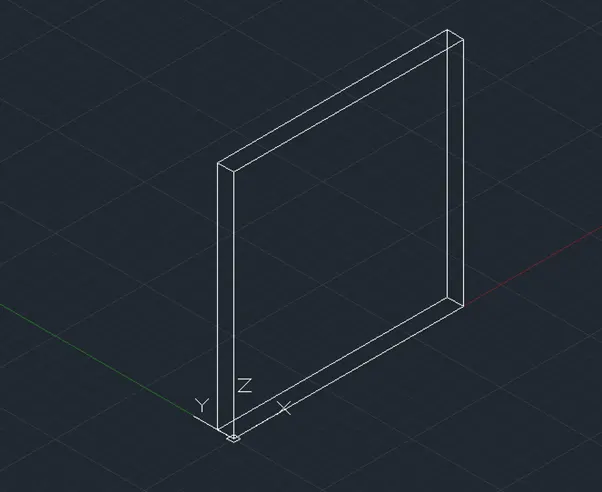
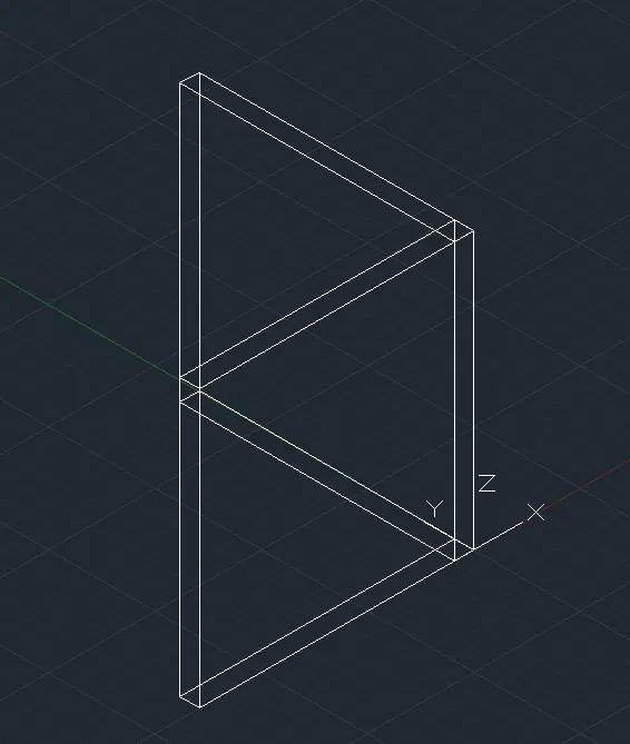

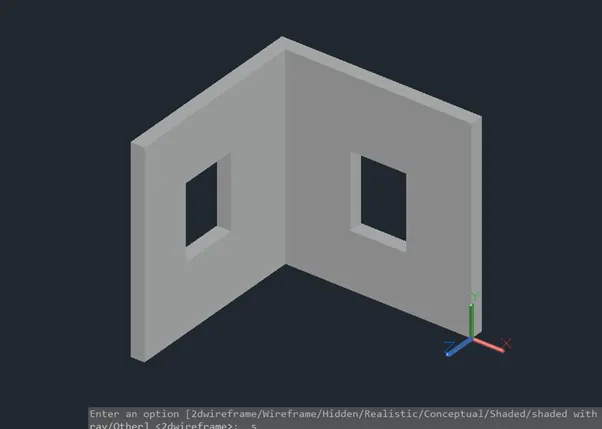
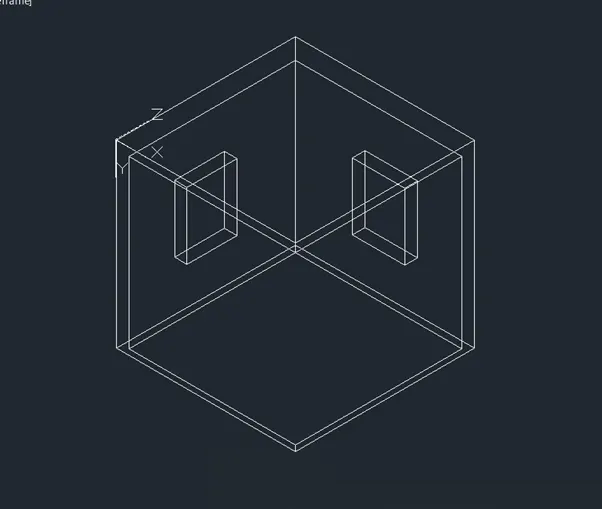
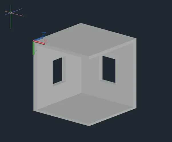
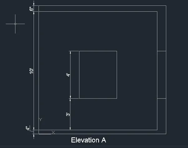
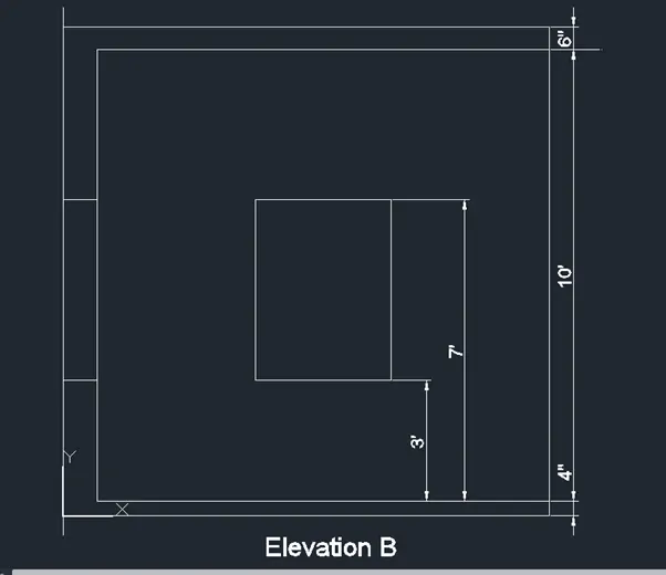
Result
Thus the 3D isometric view of a building is created.
2.
Aim
To create a 3D view of a Building Façade by using AutoCAD 3D
Procedure
- Open AutoCAD and g to 3D modelling
- Set the units as Engineering and start.
- Use rectangle commend in the Top view and give start point and then provide coordinates for the next point.
- Then create another rectangle and give coordinates.
- Then create windows as given in the plan.
- Then go to 3D view and use move commend and move the windows to required height.
- Then create region by using region commend.
- Then use extrude commend then click on the rectangle and give height.
- Select the window and give height of wind to extrude.
- The select the window and use copy commend and give the height.
- Then again use copy commend and give the height to move the window.
- Use subtract commend and select the rectangle then select the window and press enter.
- Then use union commend and select the walls.
- Then give dimension. And go to shaded the plan is visible.
Output
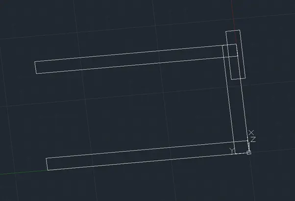
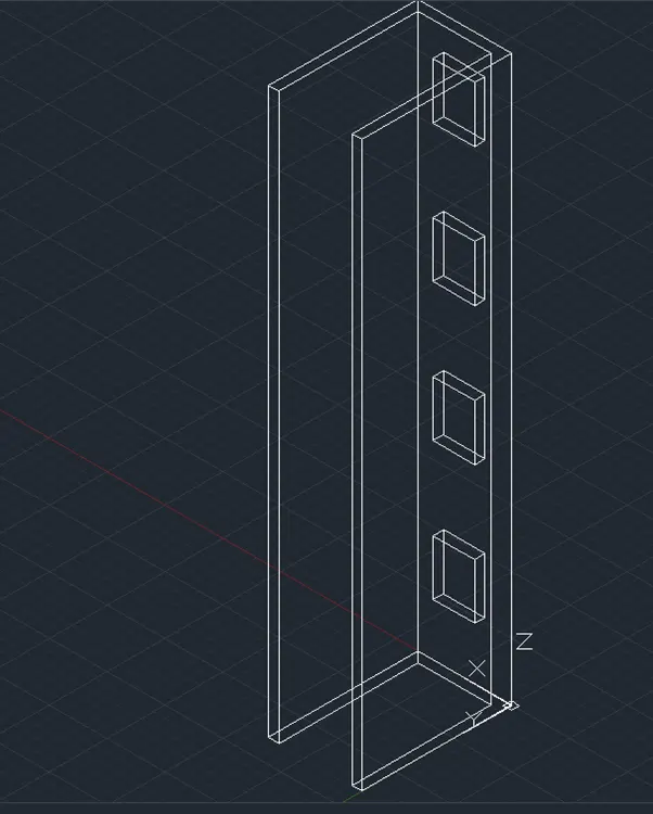
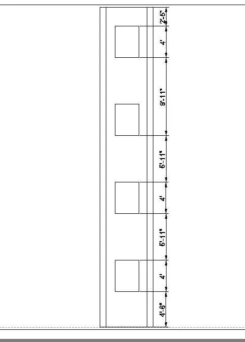
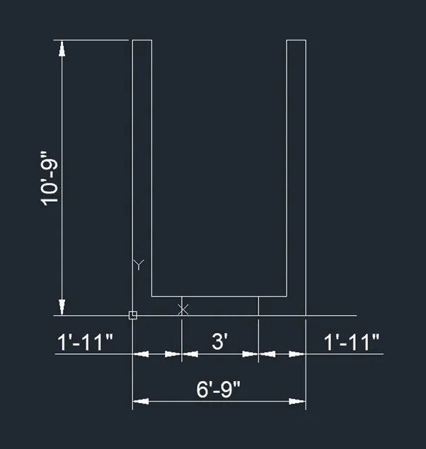
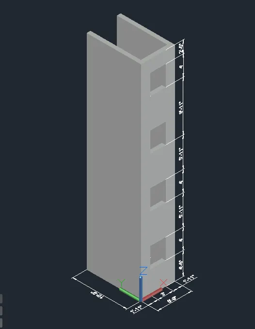
Result
Thus the 3D view of Building Facade has been created.
3.
Aim
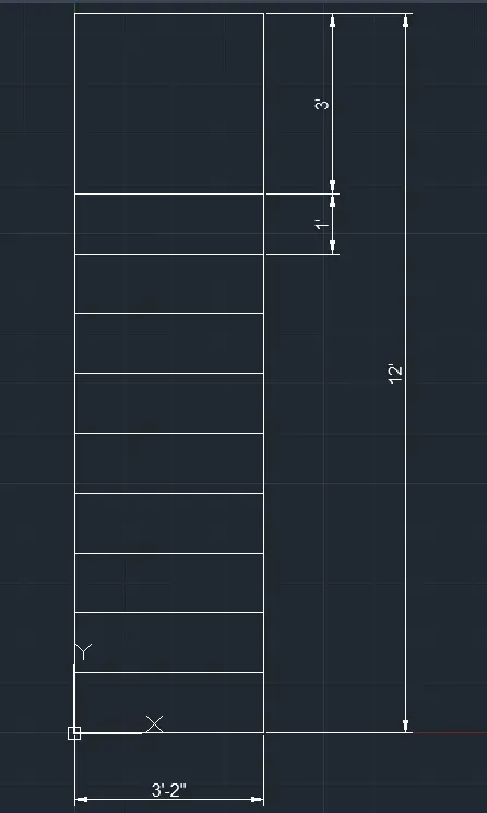
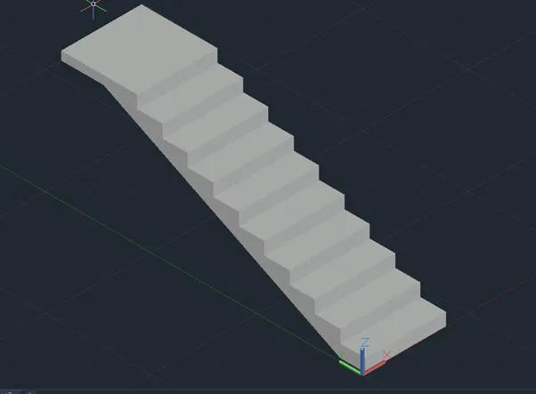
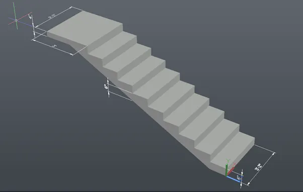
To create an isometric 3D view of a Stair case as shown in the figure.
Procedure
- Open AutoCAD and g to 3D modelling
- Set the units as Engineering and start.
- Use rectangle commend in the Top view and give start point and then provide coordinates for the next point.
- Copy the rectangle and specify the base point and place the rectangle one above the other until 9.
- Then create a landing by using rectangle.
- Then go to 3D and use extrude and extrude each rectangle at appropriate height.
- Then use union to join the stair.
- The use line commend and create the line parallel to the stair.
- Then use press and pull commend and pull the created line with stair.
- Then erase the extra lines.
Output
Result
Thus the 3D isometric view of Staircase has been created.
4.
Aim
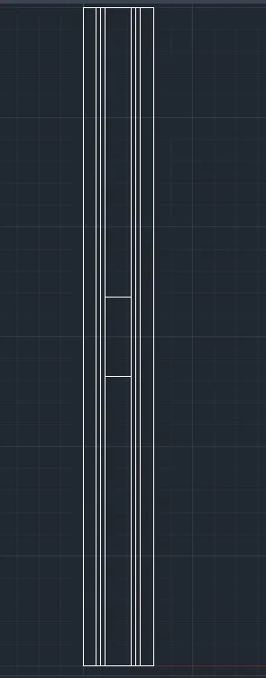
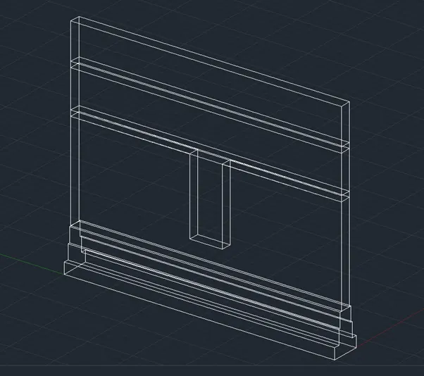
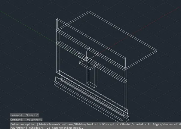
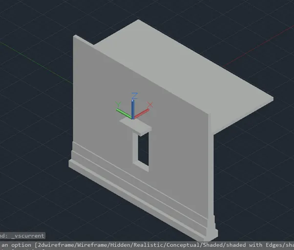
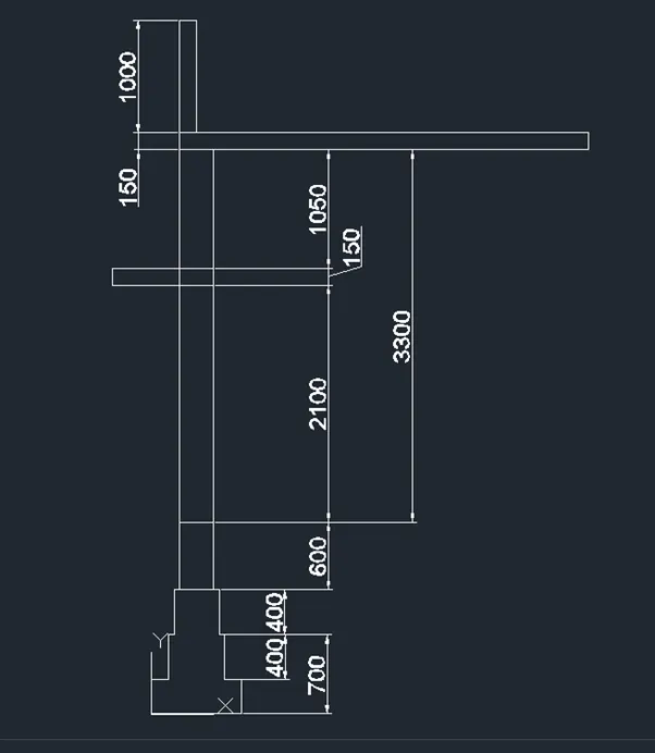
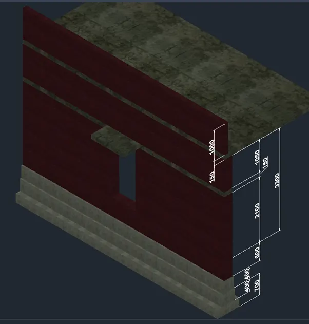
To create a 3D view of a wall with spread footing by using given plan. Also to create a rendered view of the model with materials applied.
Procedure
- Open AutoCAD and g to 3D modelling
- Set the units as Engineering and start.
- Use rectangle commend in the Top view and give start point and then provide coordinates for the next point.
- Use rectangle commend and create footing and the repeat to create the wall and the door.
- Then go to 3D view and move the rectangles to appropriate heights.
- The create region.
- Then use extrusion and extrude the foundation, footing, walls, and doors to the appropriate height.
- Then use Box to create a Lintel.
- Then use box to create wall above lintel.
- Then use box to create slab and parapet.
- Then use push pull commend and create sunshade and slab.
- The use subtract commend and delete the door area.
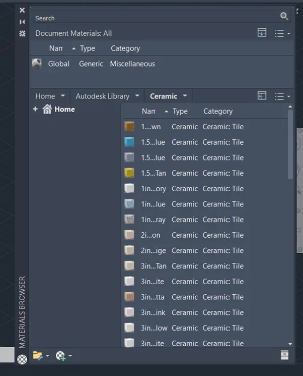
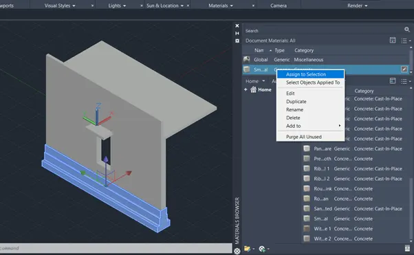
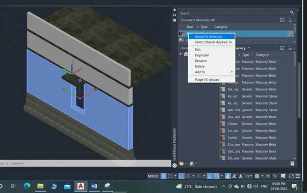
- Go to visualizer and material properties and assign the material to the wall and foundation.
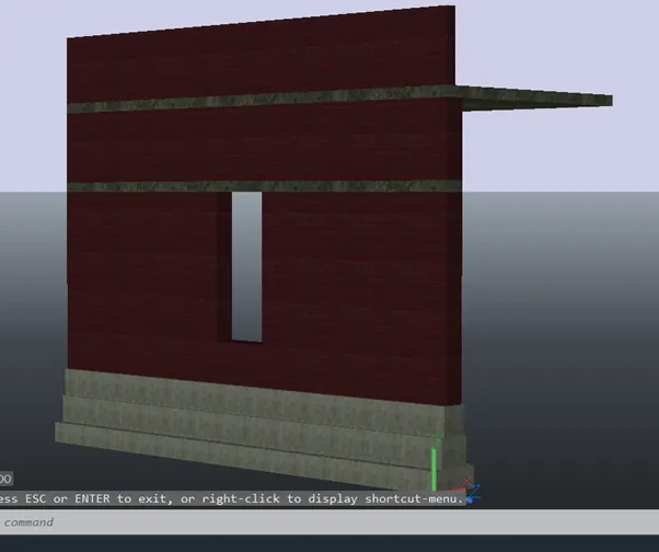
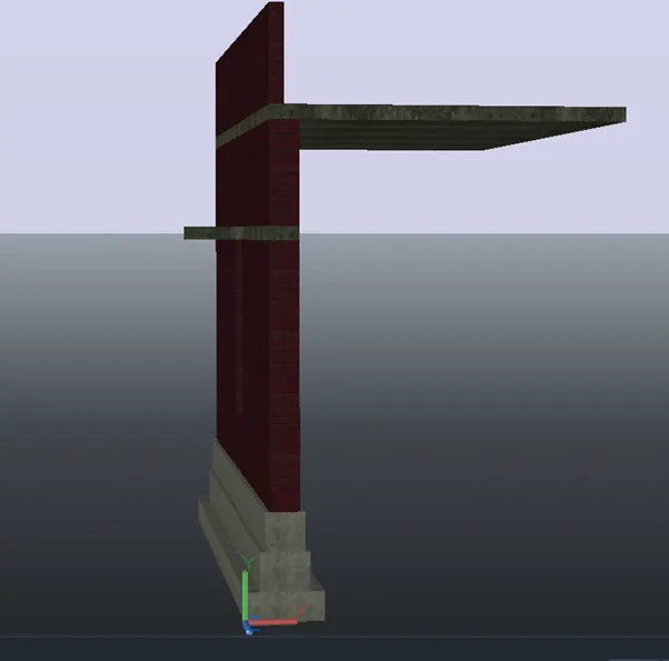
- Then use rr commend to render.
Output
Result
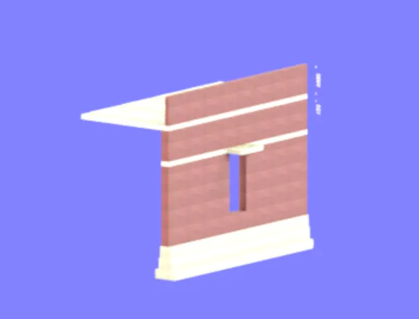
Thus the 3D wall with spread footing is created. Then the material properties are assigned and rendered.