Creating 3D Isometric view of various structural elements in AutoCAD
1. Create a 3D Isometric View of the building with plan and elevation given.
Ans1:
AIM: To create a 3D Isometric View of the given Building plan and elevation using various 3D drawing tools in AutoCad.
PROCEDURE:
- Open a new drawing with Imperial units and set the drawing settings and Architectural drawing units and setting to 3D modelling.
- Set the UCS to TOP view, visual style to 2D wireframe and draw the given plan of the building as shown below.
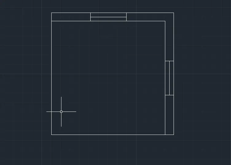
- Change the view to SW Isometric and select the region for the walls and floor of building
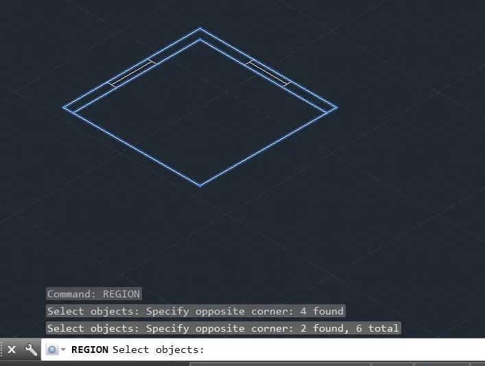
- Extrude the external rectangle of floor below for the plinth thickness
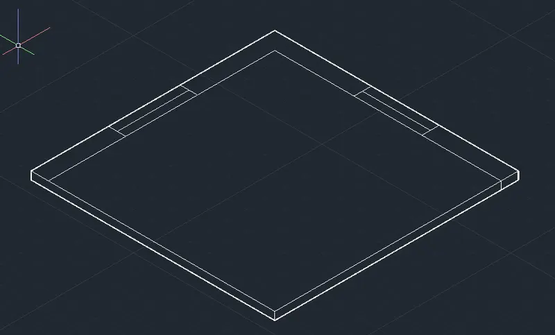
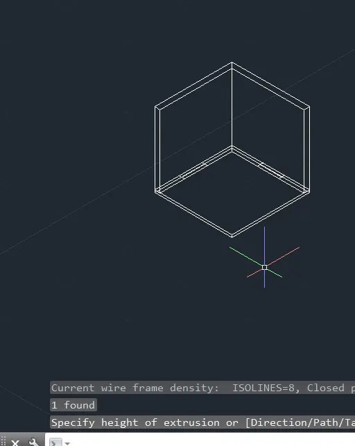
- Extrude the wall lines to the given wall height
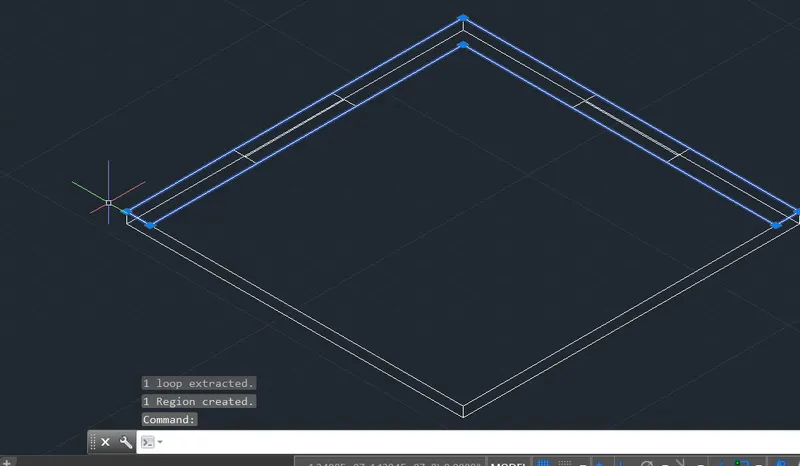
- Extruded wall shown below
- Draw the rectangle region for the windows
- Move the window rectangles to sill level
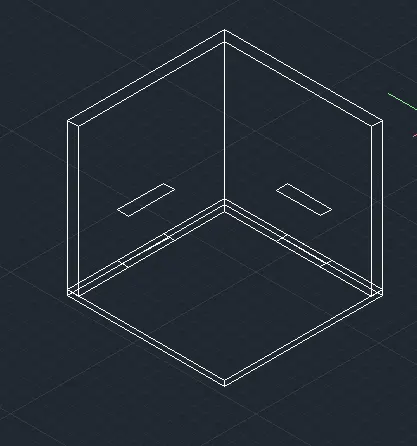
- Extrude the windows to the lintel level
- Subtract the window area from the extruded walls
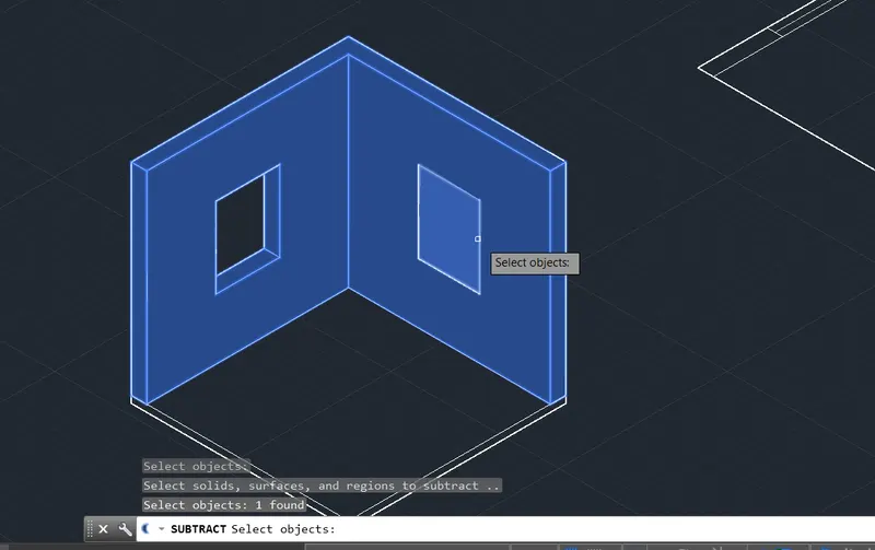
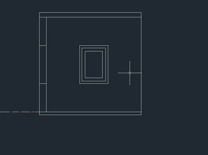
- Draw the window frames as per given drawing details
- Extrude the window for the thickness of windows and subtract the glass area from the window area.
- Draw the roof slab rectangle region and extrude to form the slab thickness
- View of plinth walls, windows and slab is shown below
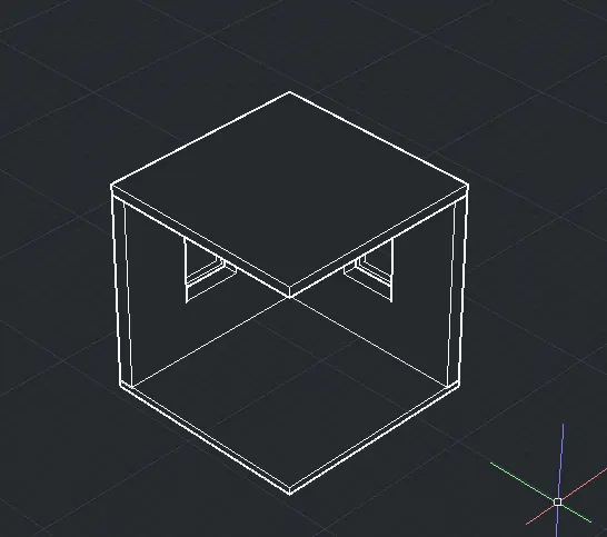
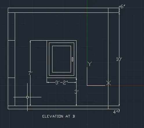
- The dimensions of the model are shown below for Elevation at B
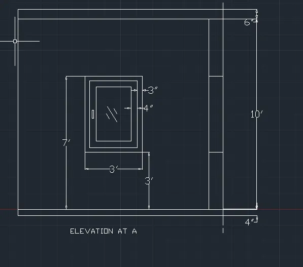
- The dimensions of the model are shown below for Elevation at A
- Final 3D model of the given building is shown below.
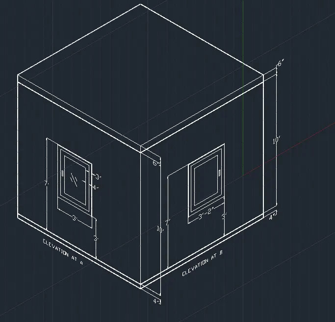
CONCLUSION: Thus we have created the 3D Isometric view of the given building plan and elevation using various 3D drawing tools in AutoCad
2. Create the 3D View of the Building Façade as given in the plan and elevation. Also, see the detail of the window.
Ans2:
AIM: To create a 3D view of Building facade as per the given plan and elevation including the detailing of window as per the given window details using various 3D drawing tools in AutoCad.
PROCEDURE:
- Open a new drawing with Imperial units and set the drawing settings and Architectural drawing units and setting to 3D modelling.
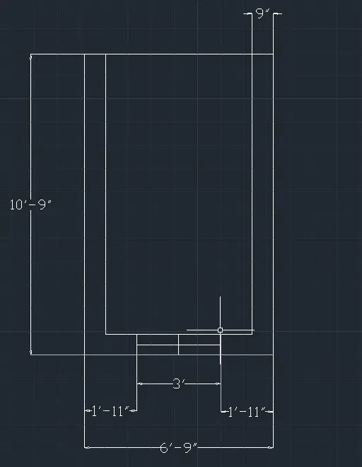
- Set the UCS to TOP view, visual style to 2D wireframe and draw the given plan of the wall as shown below.
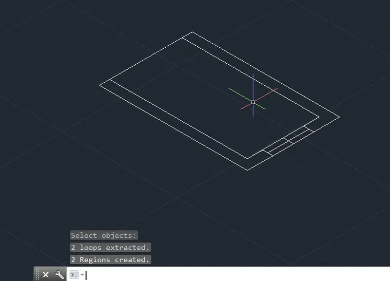
- Change the view to SW Isometric
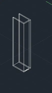
- Extrude the walls for the total height as per the given drawing
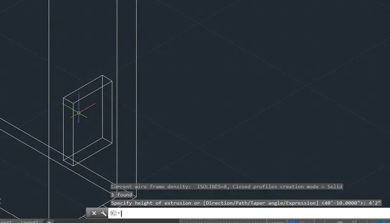
- Move the rectangle of the window to the sill levels and create region for the window
- Subtract the window regions from the wall to create wall openings
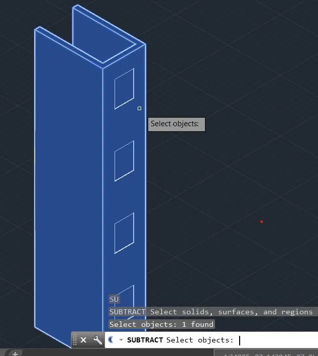
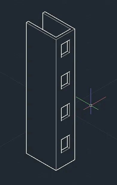
- The wall with window openings is shown below
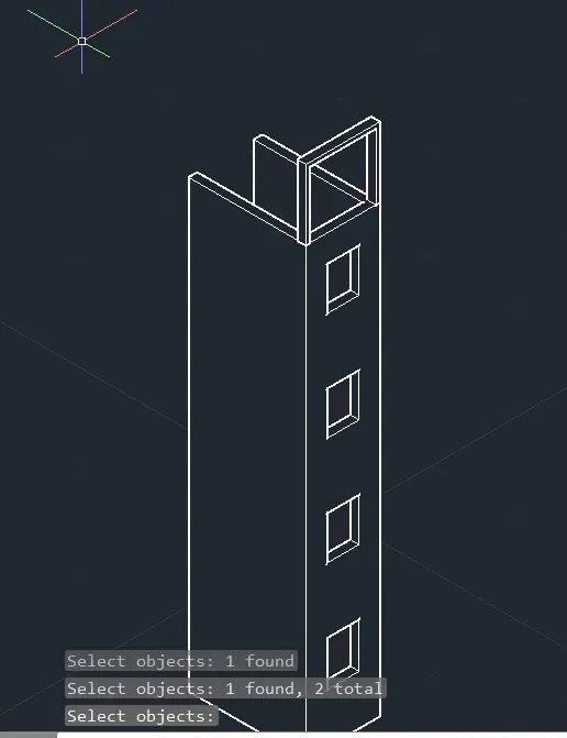
- Draw the upper frame of elevation as shown below
- Draw the window details in the window opening
- Extrude for the thickness of the window frames
- Subtract the glass region in the windows
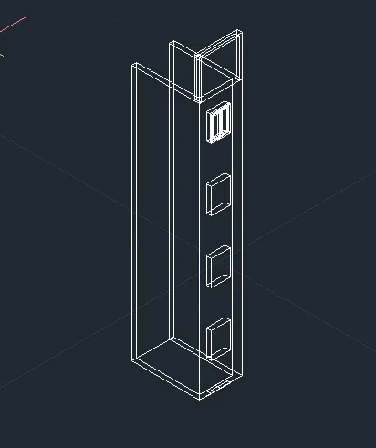
- Copy the windows to other openings
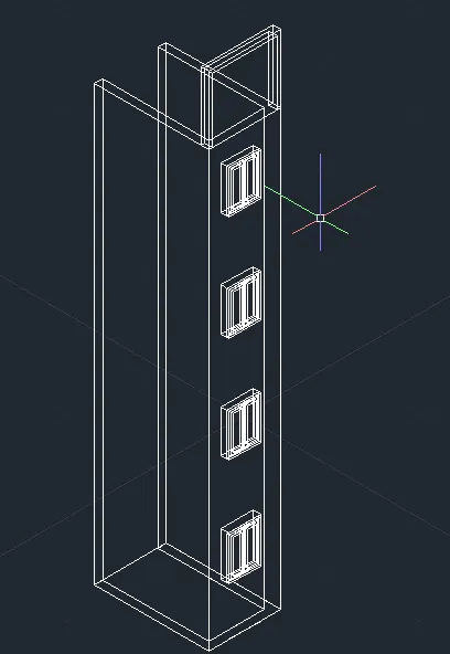
- Dimensions of the 3D model are shown below
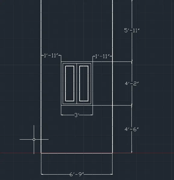
- Dimensions of the complete 3D model front are shown below
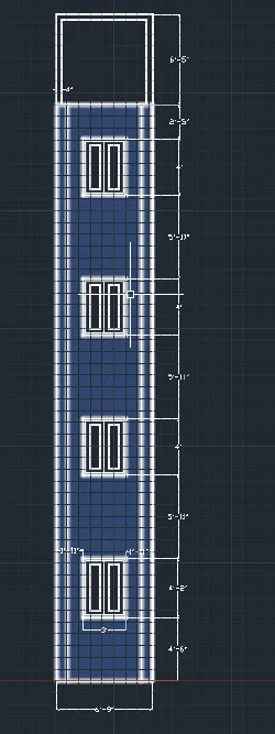
- Dimensions of the 3D model side view are shown below
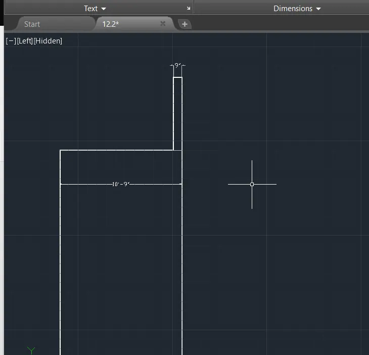
- Final view of the 3D model of the wall facade is shown below.
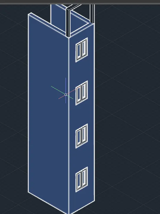
CONCLUSION: Thus we have created 3D view of Building facade as per the given plan and elevation including the detailing of window as per the given window details using various 3D drawing tools in AutoCad.
3. Create the ismoteric 3d view of a stair with railing as shown in the plan and elevation. Assume the size of the balustrades and the hand rails.
Ans3:
AIM: To create a 3D view of stair with railing as per the given plan and elevation using various 3D drawing tools in AutoCad.
PROCEDURE:
- Open a new drawing with Imperial units and set the drawing settings and Architectural drawing units and setting to 3D modelling.
- Set the UCS to TOP view, visual style to 2D wireframe and draw the staircase side view as shown below.
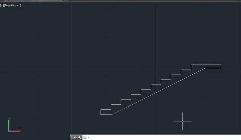
- Dimensions of the steps are verified as shown below.
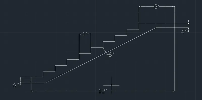
- Change the view to SW Isometric.
- Using 3D rotate rotate the staircase side view by 90 degree so that it is rising along the Z axis
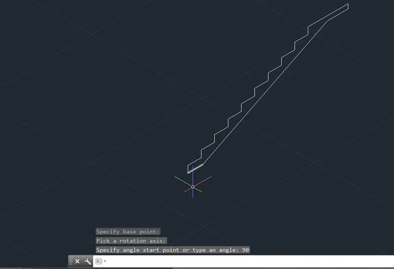
- Create region for the staircase side view
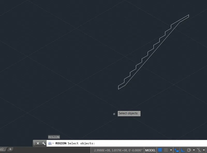
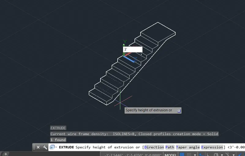
- Extrude the staircase side view region to form the width of staircase
- Draw and place the circle on the tread using the UCS location on step
- Extrude the circle to form the balustrade of given height
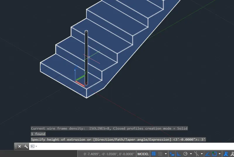
- Copy and paste the balustrade on each step and finally on the landing.
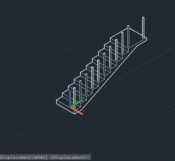
- Join the top of the balustrade by 3DPoly line
- Draw a circle of the required diameter of the hand rail
- Using Sweep command on circle and selecting the poly line the hand rail pipe is created
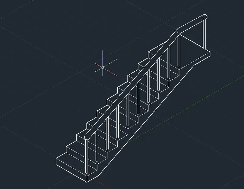
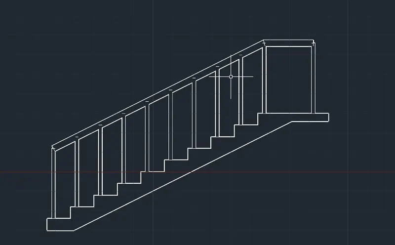
- Side view of the stair with railing is shown below
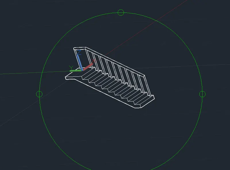
- Using 3DForbit the staircase can be viewed from all sides by rotating.
CONCLUSION: Thus we have created 3D view of stair with railing as per the given plan and elevation using various 3D drawing tools in AutoCad.
4. Create the 3D view of a Wall with spread footing . Create the Door opening only. Assume the size of the parpaet and the coping. See the plans and elevation for the details. Also, create a rendered view of the model with materials as of your choice.
Ans4:
AIM: To create a 3D view of a Wall with spread footing and door opening as per the given plan and elevation using various 3D drawing tools in AutoCad. Also the rendering to the 3D model with material details to be provided
PROCEDURE:
- Open a new drawing with Imperial units and set the drawing settings and Architectural drawing units and setting to 3D modelling.
- Set the UCS to TOP view, visual style to 2D wireframe and draw the given section veiw of the wall with spread footing as shown below.
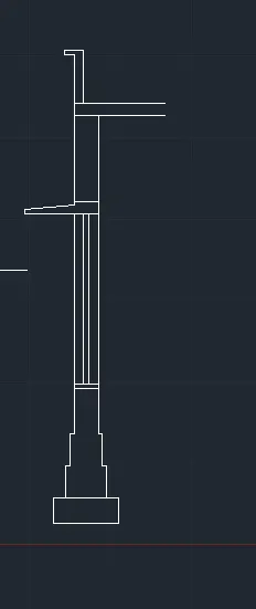
- Change the view to SW isometric view.
- Rotate the section view with 3D rotate command along the X axis so that the wall height is along Z axis
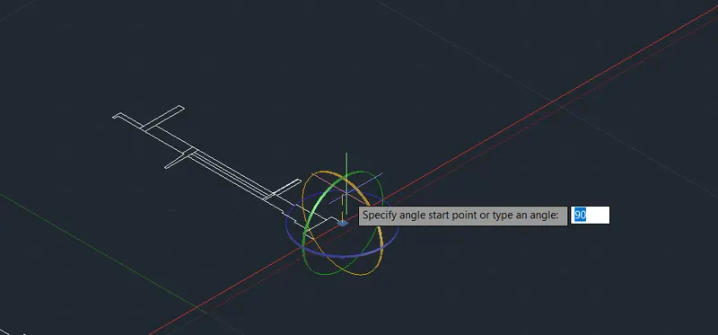
- The Wall section height along Z axis is shown below
- Draw the regions for each different elements like concrete footing, Wall footing, walls, coping, floor, lintel, sunshade, roof slab parapet etc.
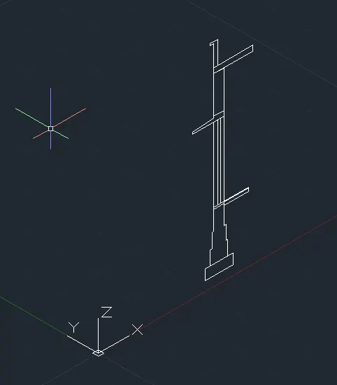
- Extrude all the elements for the length of 7500mm
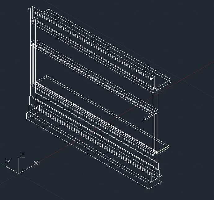
- Hidden visual style for the extruded drawing is shown below
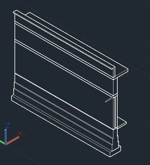
- Shift the sun shade region to required position and extrude
- Draw the door opening region
- Extrude the door opening region through both the faces of the hollow wall
- Subtract the extruded door opening to create door opening in the wall
- Draw wall for the door jamb and join with the main wall using Union command
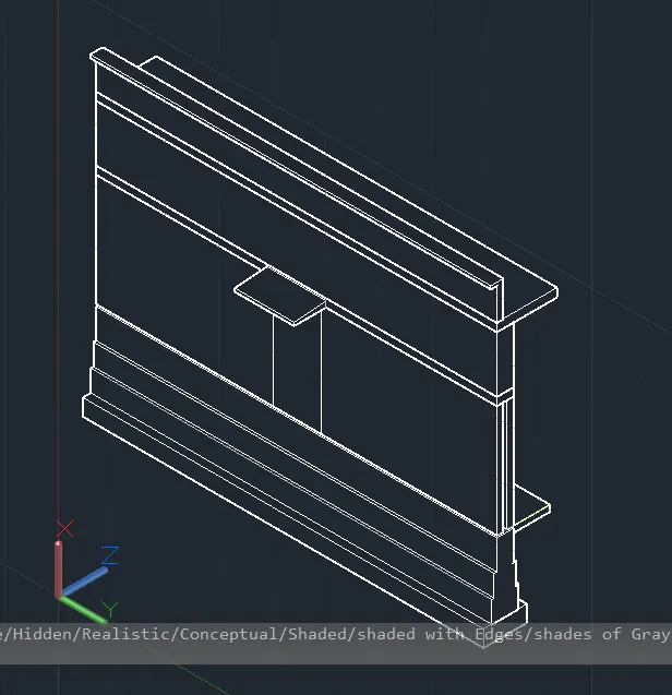
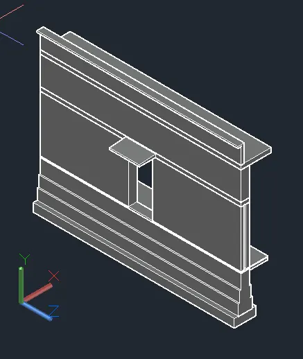
- Views of final 3D model in various visual styles are shown below for reference
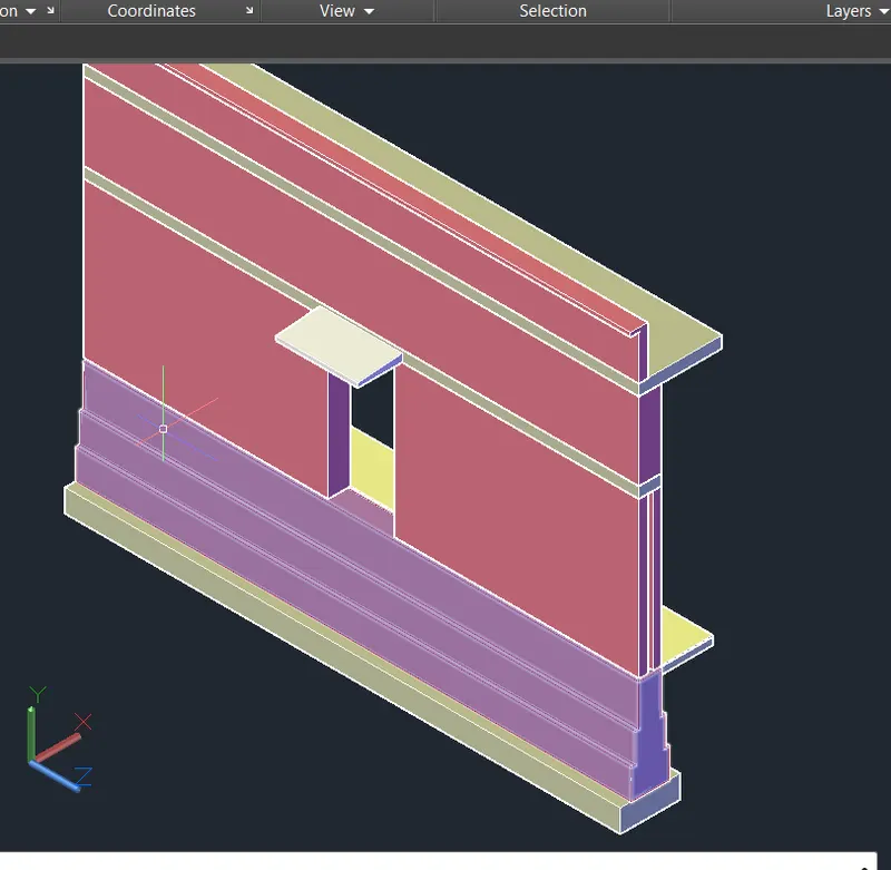
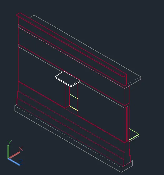
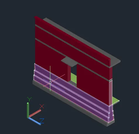
- Select the materials from the material list available through Material browser
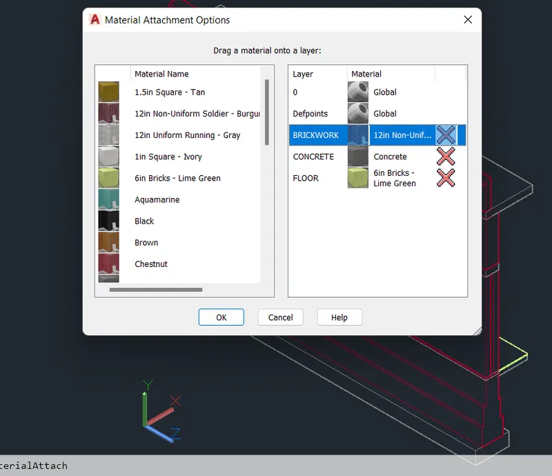
- Select the elements and apply the required material finishes for rendering the drawing.
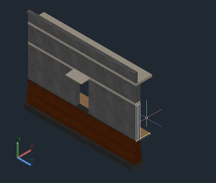
- Final rendered view of the wall with spread footing from outer side is shown below.
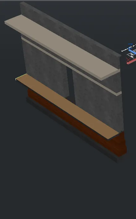
- Final rendered view of the wall with spread footing from inner side is shown below
CONCLUSION: Thus we have created 33D view of a Wall with spread footing and door opening as per the given plan and elevation using various 3D drawing tools in AutoCad. Various view with different visual styles as shown for reference. Also the rendered view of the 3D model with material details are provided.