Creating 3D Isometric view of various structural elements in AutoCAD
1.AIM
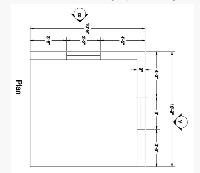
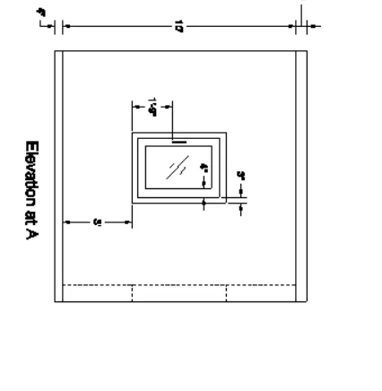
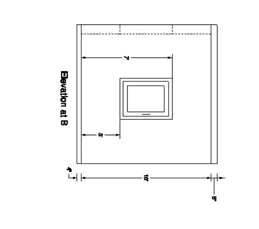
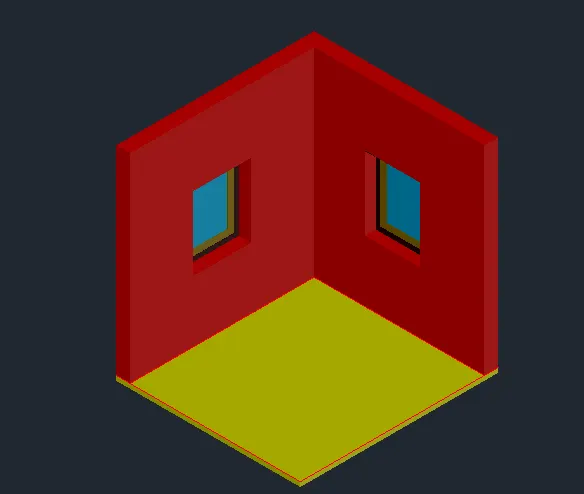
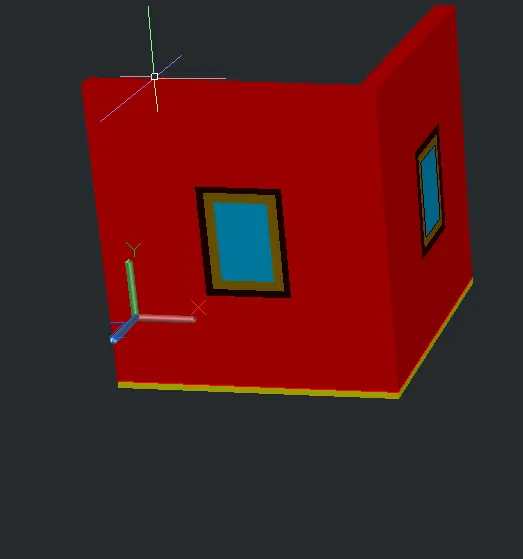
To Create a 3D Isometric View of the building with plan and elevation
COMMANDS USED
- Line
- Extrude
- Offset
- 3dorbit
- Region
- Boundary
- trim
- dimlinear
- rectangle
- ucs
- subtract
- union
- dimstyle
- 3dface
- distance
- boundary
- copy
- 3Drotate
- plan
- move
- solid edit
- explode
- erase
- units
- limits
INTRODUCTION
1.In 3D modelling, we use the design we have created using 3D drawing commands and then makes things out of it .Different types of 3D models are there and they are
- Wireframe models
- Surface models
- Soilid models
2.An isometric drawing is a 3D representation of an object, room, building or design on a 2D surface
3.One of the defining characterastics of an isometric drawing , compared to other types of 3D representation, is that the final image is not distorted
4.In an isometric drawing , the object appears as if it is being viewed from one corner , with the axes being set out from this corner point
5.Isometric drawings begin with one vertical line along which other two points are defined
6. Any lines set out from these points should be constructed at an angle of 30 degrees
PROCEDURE
STEP1
- Open a new file
- Go to settings and change view of the page from drafting to 3D modelling
- In the command line type units , select the unit and also set the precision
- In the command line type 'LIMITS' and specify the limits at lower left corner and upper right corner as
- Then zoom all
STEP2
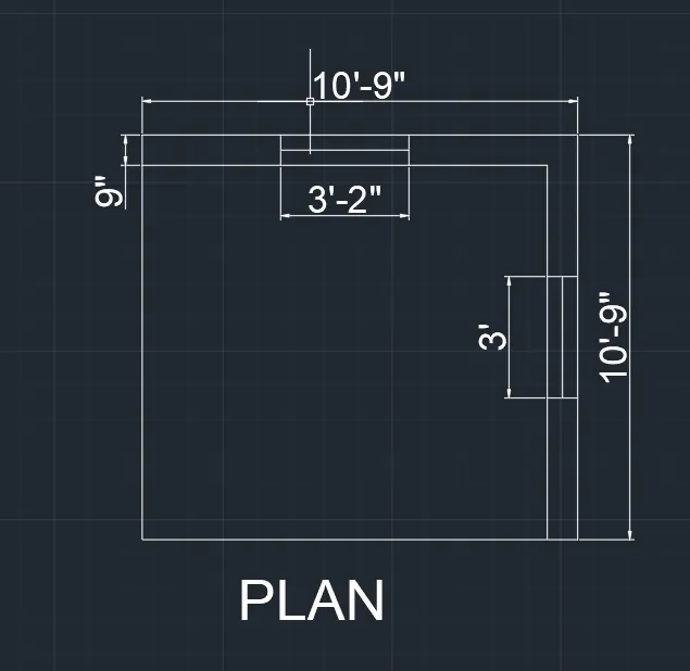
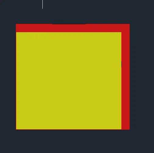
- Using the rectangular command draw rectangle of 10'-9"*10'-9"
- Give wall thickness as 9"
- mark the window
STEP3
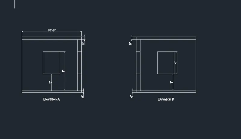
- Using the line line command elevation A and B are drawn
- dimensions are marked using dimlinear command
STEP4
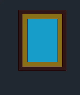
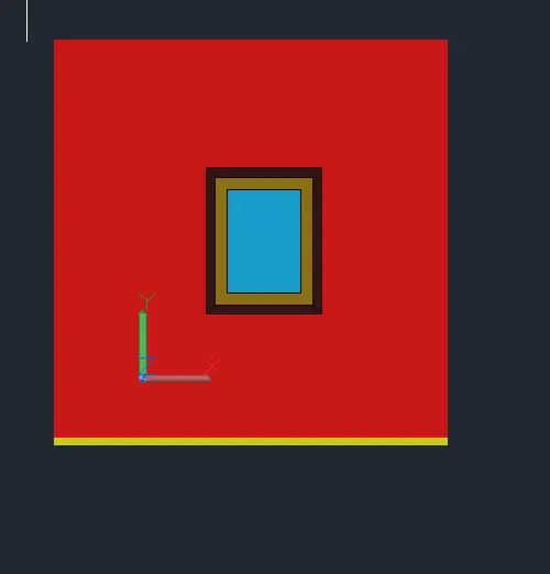
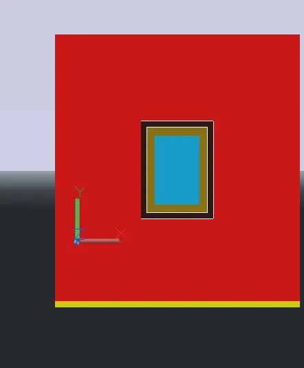
- Then we draw window of size 3'*4' and 3'-2"*4" using rectangular command
- by using offset command offset it by 3" and 4"
- using line command
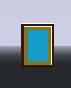
- using extrude command will extrude it
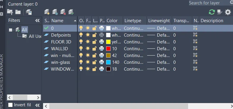
- using layer command we will layer it
- change the layer for all the boxes respectively
- we can do that using boundary command and subtract command
- Then all layers are extruded
STEP5
- Take the plan drawn in topview and change it to 3d view by clicking the home button of view cube
- Set the ucs as world
- create boundary using "BO" command and extrude it to total height of 10'-9" using extrude command
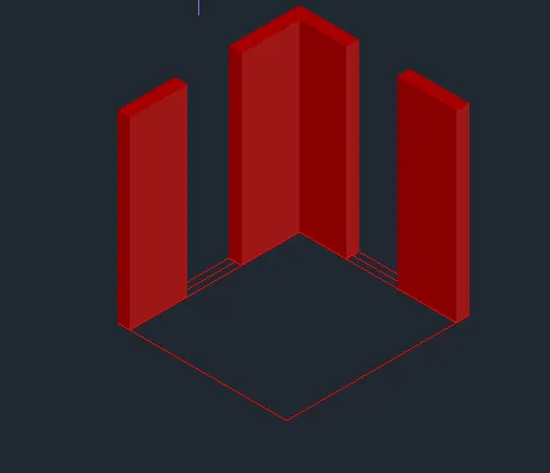
- inorder to draw the window draw rectangle at the space of windows and change them into boundaries
- then extude it using the extude command , leave the space for the window
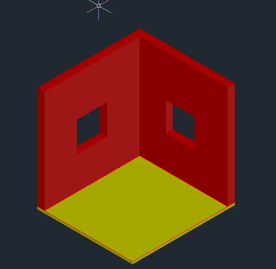
- Now attatch the window to the space
STEP6
- Using the visualize tab
- click on the new view and give name as view 1
- click on the current view and click ok
- this 3 views are created as View1, View2, View 3
RESULT
3D Isometric View of the building with plan and elevation is created
---------------------------------------------------------------------------------------------------------------------------------------------
2.AIM
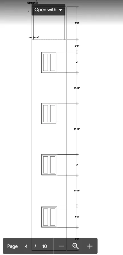
To Create the 3D View of the Building Façade as in the plan and elevation
COMMANDS USED
- Line
- Extrude
- Offset
- 3dorbit
- Region
- Boundary
- trim
- dimlinear
- rectangle
- ucs
- subtract
- union
- dimstyle
- 3dface
- distance
- boundary
- copy
- 3Drotate
- plan
- move
- solid edit
- explode
- erase
- units
- limits
INTRODUCTION
1.In 3D modelling, we use the design we have created using 3D drawing commands and then makes things out of it .Different types of 3D models are there and they are
- Wireframe models
- Surface models
- Soilid models
2.An isometric drawing is a 3D representation of an object, room, building or design on a 2D surface
3.One of the defining characterastics of an isometric drawing , compared to other types of 3D representation, is that the final image is not distorted
4.In an isometric drawing , the object appears as if it is being viewed from one corner , with the axes being set out from this corner point
5.Isometric drawings begin with one vertical line along which other two points are defined
6. Any lines set out from these points should be constructed at an angle of 30 degrees
PROCEDURE
STEP1
- Open a new file
- Go to settings and change view of the page from drafting to 3D modelling
- In the command line type units , select the unit and also set the precision
- In the command line type 'LIMITS' and specify the limits at lower left corner and upper right corner as
- Then zoom all
STEP2
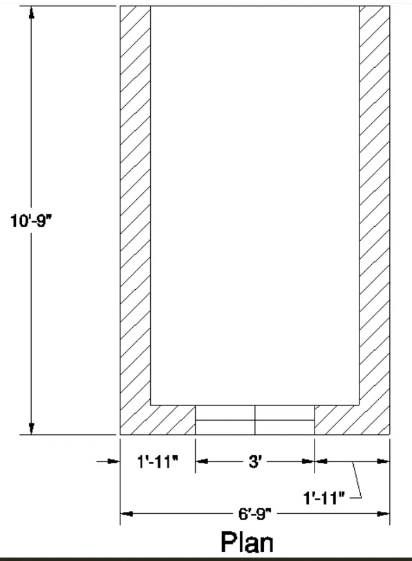
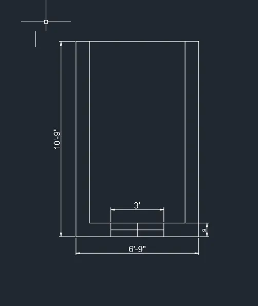
- using the rectangular command draw rectangle 6'-9"*10'-9"
- Using the offset command give the wall thickness as 9"
- using dimlinear command mark the dimension
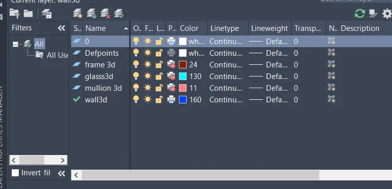
- Using the layercommand create layers
STEP3
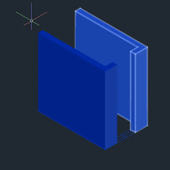
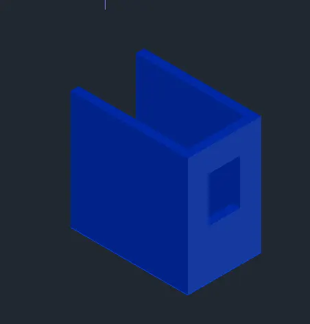
- Take the plan drawn in topview and change it to 3d view by clicking the home button of view cube
- Set the ucs as world
- create boundary using "BO" command and extrude it to total height of 10'-9" using extrude command
- select all the walls and group it using the group command
- inorder to draw the window draw rectangle at the space of windows and change them into boundaries
- then extude it using the extude command , leave the space for the window
STEP4
Creating window
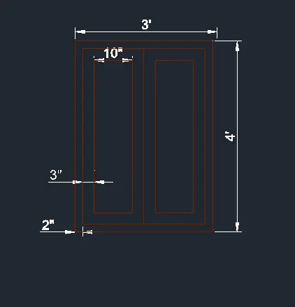
- Using the ucs command and click on the face and select the face in which window has to be created
- Draw a rectangle of 3'*4'
- Using the offset command offset rectangle to inside by 2"
- offset the offsetted rectangle to inside to a distance by 3"
- Using the line command draw the centerline connceting the midpoints
- Offset the llines to both sides to adistance of 3"
- trim off all the unwanted lines
- using dimlinear dimensions are marked
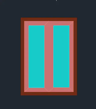
- Using "BO" command and click the pick points
- Click inside the window frame area and press enter
- use the subtract command from bigger region subtract the smaller region
- same procedure do for mullions and glass
- all the layers are extruded to give the window projections
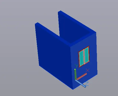
- Place the created window in position
STEP 5
- Group all the items created
- Copy the block having 4'*3' height window and place it 3 times
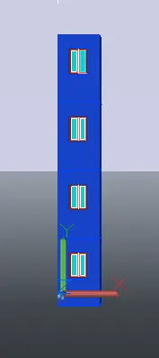
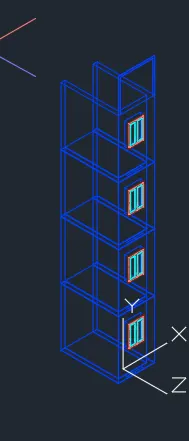
- Now we need to create the top part
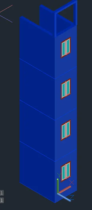
- using line command 4" wall with height of 6'-5" from top
- Using boundary command create boundary and extrude the created boundary to 9"
STEP6
- Using the visualize tab
- click on the new view and give name as view 1
- click on the current view and click ok
- this 3 views are created as View1, View2, View 3
RESULT
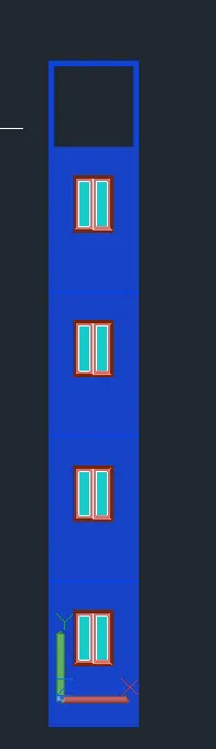
3D View of the Building Façade is created
---------------------------------------------------------------------------------------------------------------------------------------------
3.AIM
To Create the ismoteric 3d view of a stair with railing
COMMANDS USED
- Line
- Extrude
- Offset
- 3dorbit
- Region
- Boundary
- trim
- dimlinear
- rectangle
- ucs
- subtract
- union
- dimstyle
- 3dface
- distance
- boundary
- copy
- 3Drotate
- plan
- move
- solid edit
- explode
- erase
- units
- limits
INTRODUCTION
1.In 3D modelling, we use the design we have created using 3D drawing commands and then makes things out of it .Different types of 3D models are there and they are
- Wireframe models
- Surface models
- Soilid models
2.An isometric drawing is a 3D representation of an object, room, building or design on a 2D surface
3.One of the defining characterastics of an isometric drawing , compared to other types of 3D representation, is that the final image is not distorted
4.In an isometric drawing , the object appears as if it is being viewed from one corner , with the axes being set out from this corner point
5.Isometric drawings begin with one vertical line along which other two points are defined
6. Any lines set out from these points should be constructed at an angle of 30 degrees
PROCEDURE
STEP1
- Open a new file
- Go to settings and change view of the page from drafting to 3D modelling
- In the command line type units , select the unit and also set the precision
- In the command line type 'LIMITS' and specify the limits at lower left corner and upper right corner as
- Then zoom all
STEP2
Creating layers
- Open the layer property and create new layers
- Layers are created
STEP3
Plan view
- Change the current layer to stairs
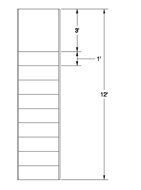
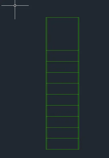
- using the rectangle command draw rectangle of 3'*12'
- Using explode command explode the rectangle
- using the offset command offset 1" from side edges
- Offset from the bottom edge to upside to a distance of 1'
STEP4
Side view
- by clicking on the home button of view cube we can change the view to 3d
- set ucs as right
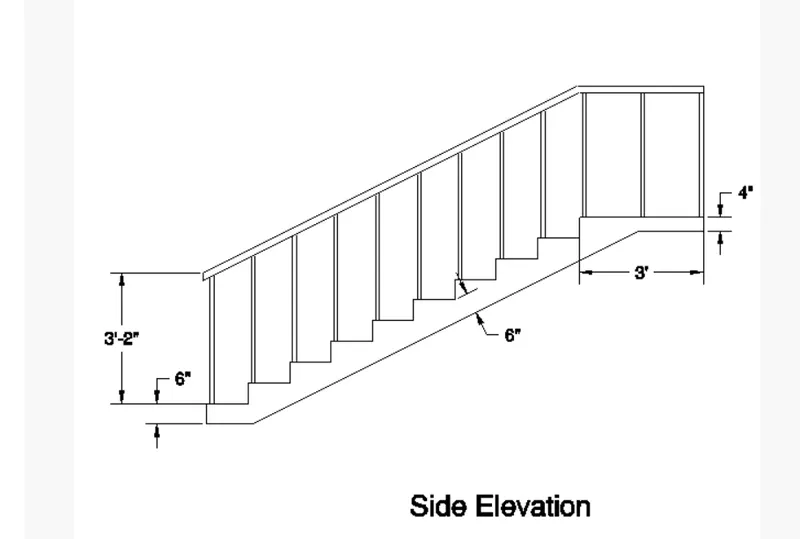
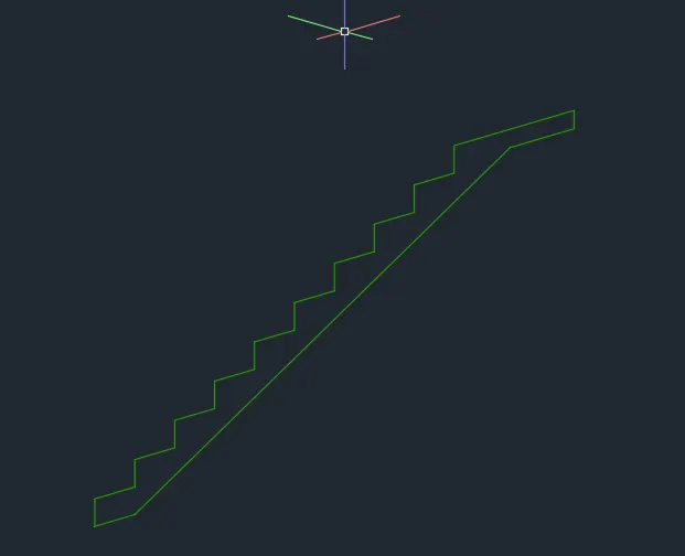
- using line command draw vertical line of 6" and horizontal line of 1'
- repeat the same process to draw steps
- after reaching last step draw landing of 3'
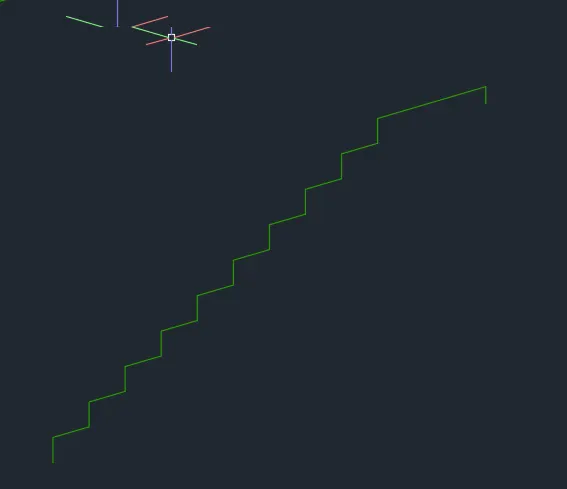
- from there to bottom draw line of 6" and 1'-6" towards back
- draw a line of 1' at bottom step
- join this to form a slab
- set ucs as world
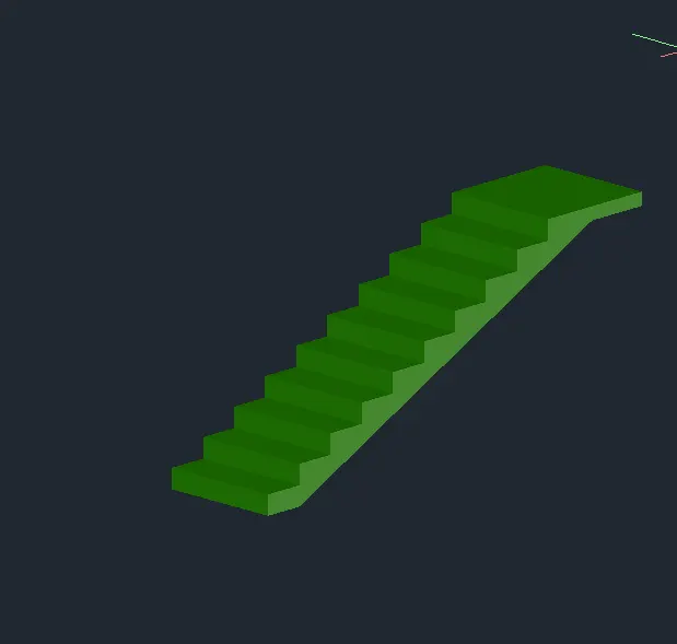
- create region of the side viewv
- using the extrude command extrude the side view to a distance of 3'
STEP5
Hand rail
- change the layer to handrails
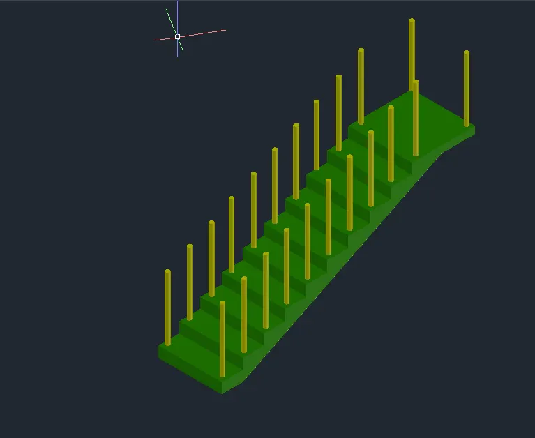
- draw a circle and change into region
- using extrude command extrude it to height of 3'
- place this in each step and copy to other side
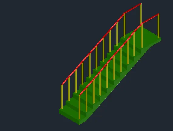
- using polyline draw line connecting all the top edges of handrails
- change the ucs front , draw a circle
- using the sweep command circle as sweep object select the polyline as path of sweep
- copy the same to other side
STEP6
- Using the visualize tab
- click on the new view and give name as view 1
- click on the current view and click ok
RESULT
ismoteric 3d view of a stair with railing is created
-------------------------------------------------------------------------------------------------------------------------------------
4.AIM
To Create the 3D view of a Wall with spread footing
COMMANDS USED
- Line
- Extrude
- Offset
- 3dorbit
- Region
- Boundary
- trim
- dimlinear
- rectangle
- ucs
- subtract
- union
- dimstyle
- 3dface
- distance
- boundary
- copy
- 3Drotate
- plan
- move
- solid edit
- explode
- erase
- units
- limits
INTRODUCTION
1.In 3D modelling, we use the design we have created using 3D drawing commands and then makes things out of it .Different types of 3D models are there and they are
- Wireframe models
- Surface models
- Soilid models
2.An isometric drawing is a 3D representation of an object, room, building or design on a 2D surface
3.One of the defining characterastics of an isometric drawing , compared to other types of 3D representation, is that the final image is not distorted
4.In an isometric drawing , the object appears as if it is being viewed from one corner , with the axes being set out from this corner point
5.Isometric drawings begin with one vertical line along which other two points are defined
6. Any lines set out from these points should be constructed at an angle of 30 degrees
PROCEDURE
STEP1
- Open a new file
- Go to settings and change view of the page from drafting to 3D modelling
- In the command line type units , select the unit and also set the precision
- In the command line type 'LIMITS' and specify the limits at lower left corner and upper right corner as
- Then zoom all
STEP2
Creating layers
- Open the layer property and create new layers
- Layers are created
STEP3
Creating plan view of wall with spread footing
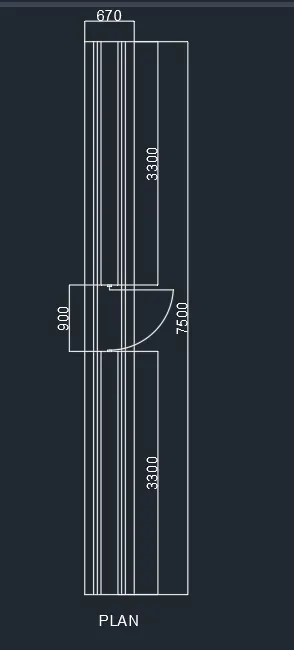
- Using rectangular command draw rectangle with dimensions 670*7500
- Using the offset command offset the rectangle to inside to a distance of 120mm
- Using the offset command offset the rectangle to inside to a distance of 50mm twice
- Explode all the offseted rectangle
- delete the top and bottom edges of the exploded rectangle
- using extend command extend it upto the outer rectangle
STEP4
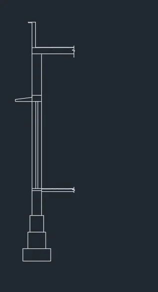
- Using the rectangular command draw rectangle with dimension 230*3300
- Then draw roof of thickness 150mm and draw a parapet wall of height 600mm
- then again by using rectangular command drawing footing with dimension 230*600 below the ground level
- 330*400 below the first level
- 430*400 below the second level
- trim the unwanted lines
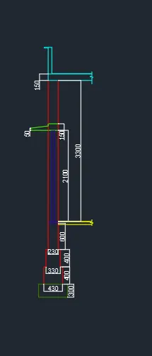
- Dimensions are marked using dimlinear command
- layer properties are given
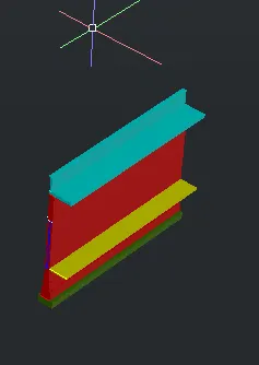
- using boundary command boundaries are created for each layer
- then by using extude command it is extruded to a distance of 7500mm
- by using the ucs face command door is drawn using rectangle and extruded
- then it is subtracted
- similarly door shade is created with door opening
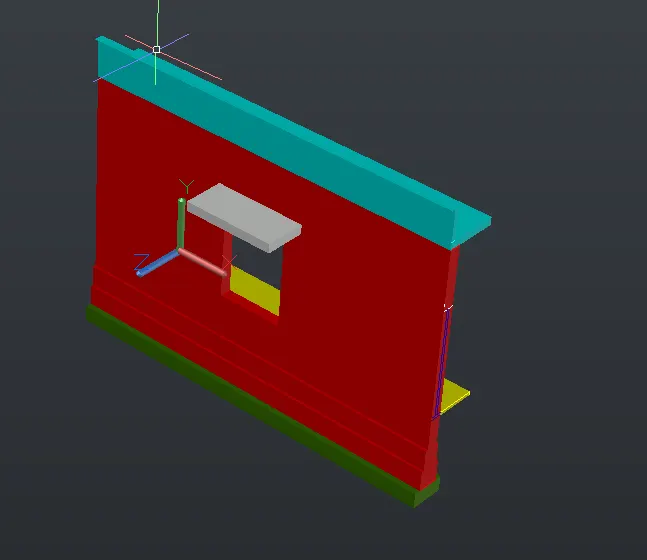
STEP5
RENDERING
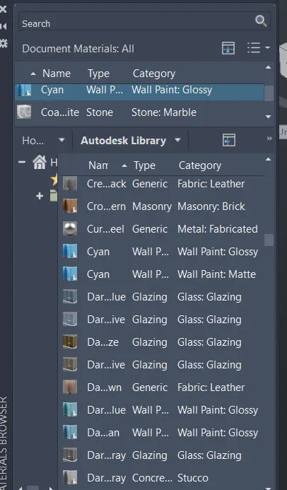
- Rendering is done by adding material using the material browser
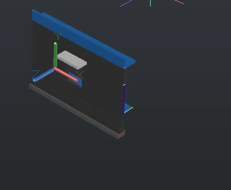
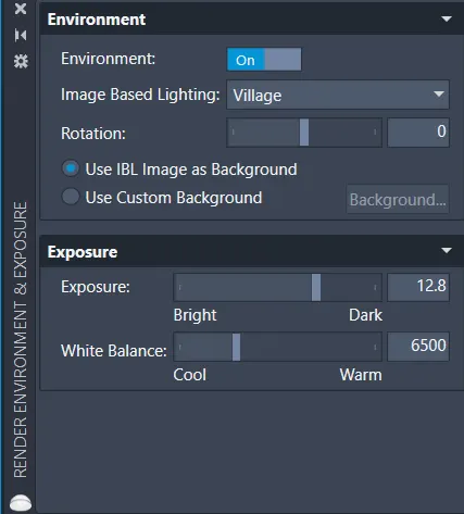
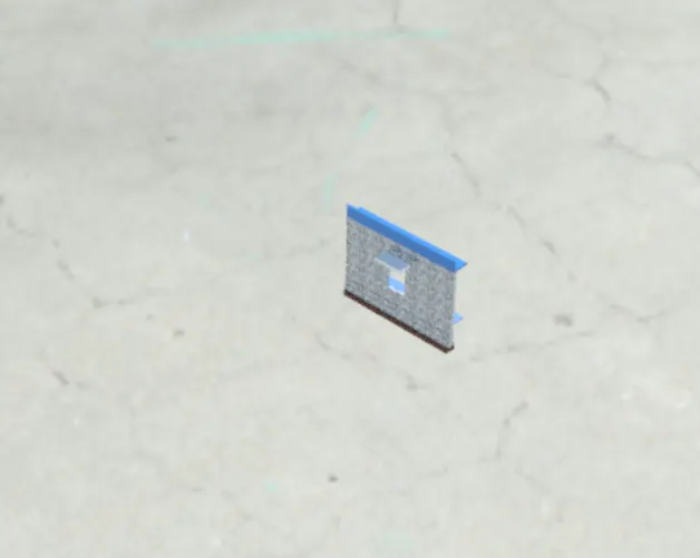
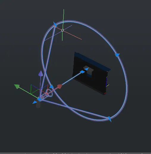
- lights
- torch light is placed infront of the door with falloff angle as 50 and hotspot angle as 85
STEP6
- Using the visualize tab
- click on the new view and give name as view 1
- click on the current view and click ok
RESULT
---------------------------------------------------------------------------------------------------------------------------------------------