Creating 3D Isometric view of various structural elements in AutoCAD
Aim:
To create a 3D isometric view of the building with the given plan and elevation.
Introduction:
Create the isometric view of the building create the plan in the plan view of 3D modeling space and use extrude command to ectrude the plan. The size of the building is 10'9''X10'9'', Wall thickness is 9'', window sizes are 3'2''X4' and 3'X4'. Most commonly used commands are line, rectangle, region, extrude, presspull and align.
Procedure:
- Open Autocad software in metric units.
- Set the units as engineering and precision as 0'0''
- Change the workspace to 3D modeling.
- Use 'plan' command set the plan view.
- Create a rectangle of size 10'9''X10'9''
- Explode the rectangle.
- Offset the left and top line at a distance of 9''
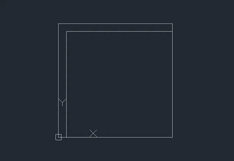
- Offset the bottom line at 3'5'' and 3'2'' and right side line at 3'6'' and 3'
- Create a window opening.
- Use 'Trim' command to remove the unwanted lines.
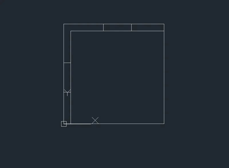
- Change the view to south-west isometric.
- Use 'Region' command create a surface of the individual objects in the plan.
- Change the visual style to conceptual.
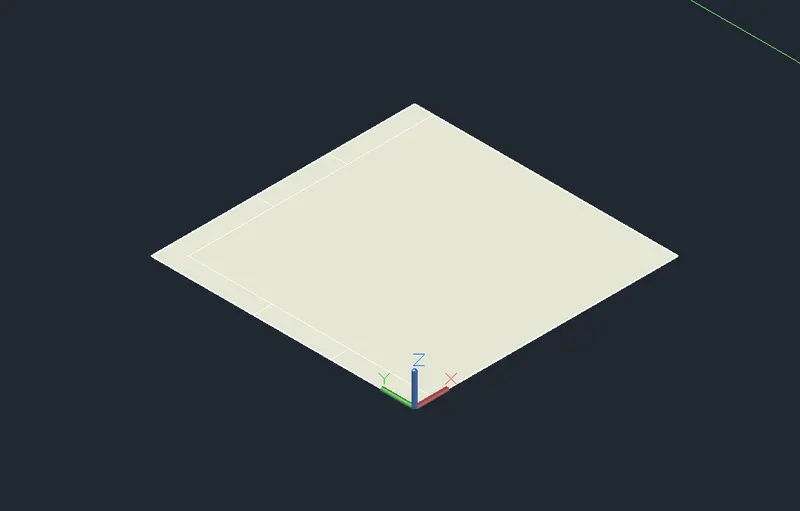
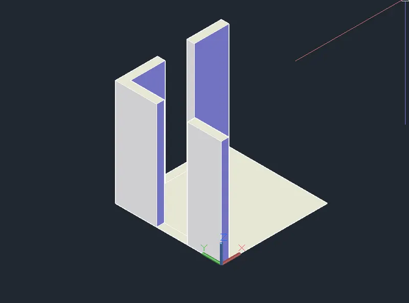
- Use 'Extrude' command extrude the wall at a height of 10'4''
- Extrude the floor slab at a height of 4''
- Window creation.
- Create a rectangle of size 3'2''X4'
- Offset the rectangle at 3'' and 4'' respectively.
- Use move tool, move the offseted rectangle to some distance.
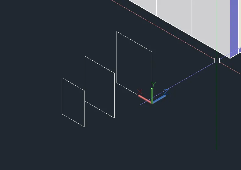
- Use 'Region' command to make surface of the rectangles.
- Extrude the first rectangle surface at 4''
- Extrude the second rectangle surface to intrude the first rectangle.
- Use 'Subtract' tool subtract the inner rectangle. to make the cutout.
- Follow the same procedure to create a cutout in the second rectangle.
- Use 'Align' tool align the rectangles extruded to make a window.
- Make the handle like structure by using rectangle, region and extrude tools.
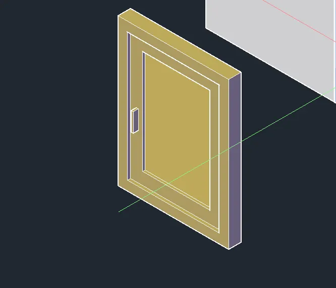
- Change the UCS at the face of the window
- Create a rectangle of size 3'2''X4'
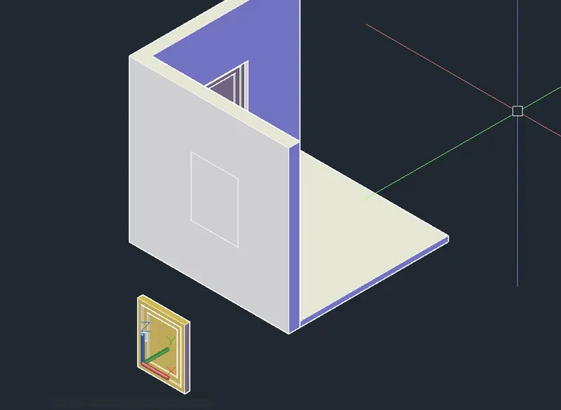
- Use 'presspull' tool pull the rectangle.
- Make a cutout of window in the wall.
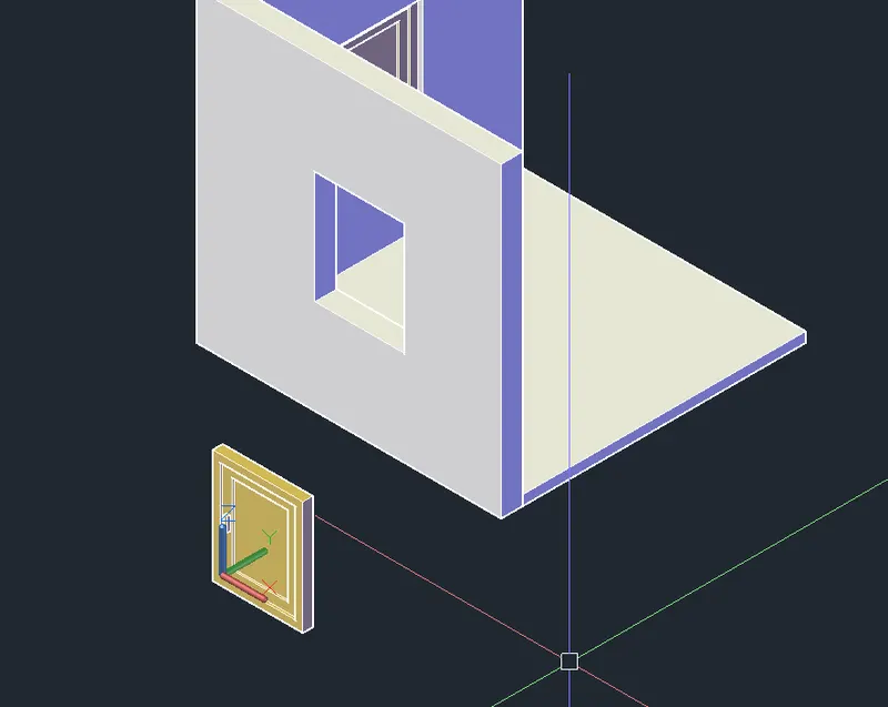
- Use 'Align' tool.
- Place the window at the cutout made in the wall.
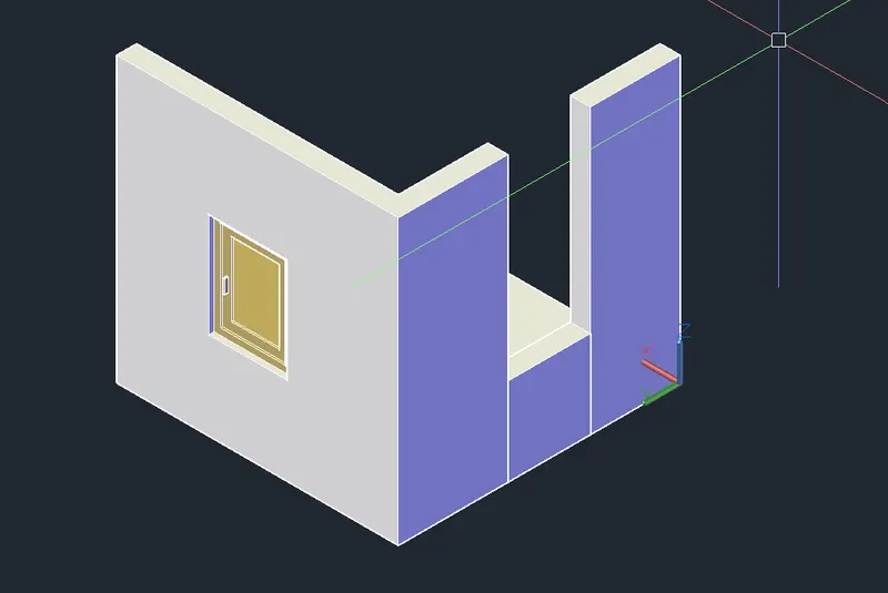
- Change the view to south-West isometric.
- Follow the same procedure to create and fit the window in other side of the wall.
- Change UCS at the top of the wall.
- Create a rectangle of size 10'9''X10'9''
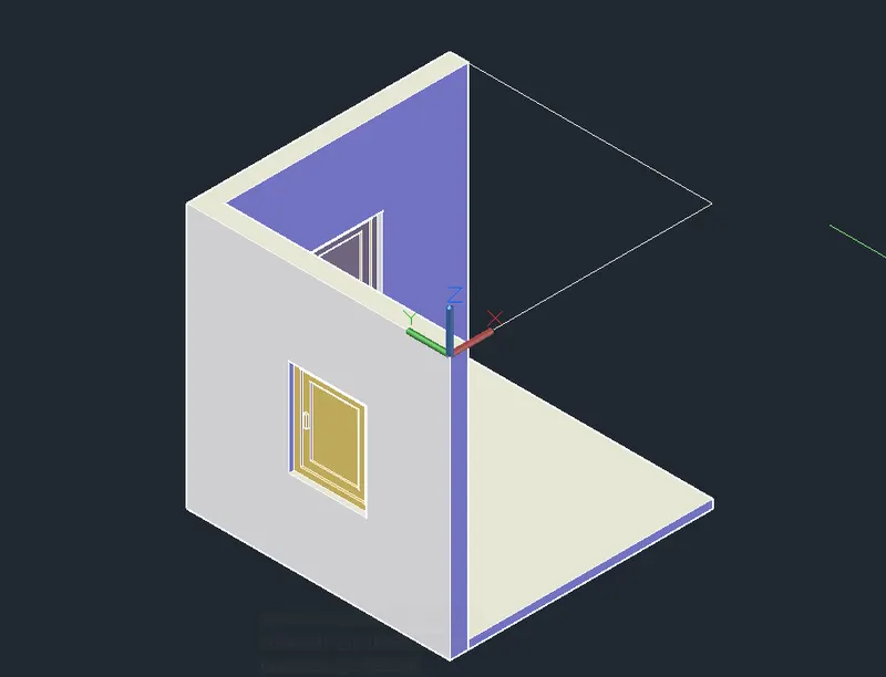
- Use 'Region' to make the rectangle as a surface.
- Use 'Extrude' tool extrude the rectangle surface at a height of 6''
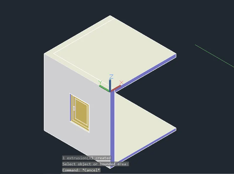
Result:
The isometric view of the building is created.
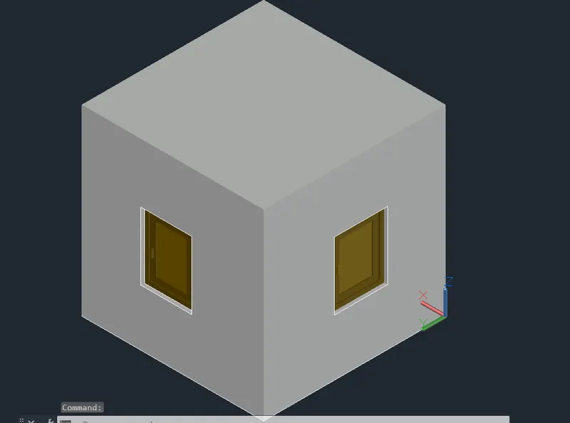
North-West isometric view.
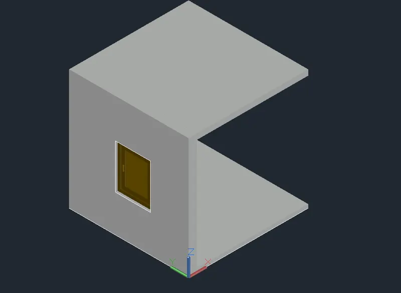
South-West isometric view.
Aim:
To create the 3D view of the building facade as given in the plan and elevation.
Introduction:
Create the plan of the building of size 6'9''X10'9'' in the plan view and using region, extrude, copy tools to create the facade of the building. The window size are 3'X4'
Procedure:
- Open Autocad software in metric units.
- Set the units as engineering and precision as 0'0''
- Change the workspace to 3D modeling.
- Use 'plan' command set the plan view.
- Create plan.
- Create a rectangle of size 6'9''X10'9'' by using rectangle tool.
- Explode it by using 'Explode' command.
- Offset the right, left and bottom side line at a distance of 9''
- Offset the outer wall line at 1'11'' and offset the offseted line at a distance of 3'
- Use trim command, trim the unwanted lines.
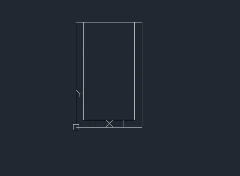
- Switch the view to South-West isometric.
- Create boundary of the walls and window.
- Use 'Region' command to create surface.
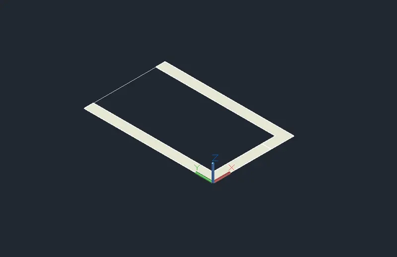
- Create windows.
- Create a rectangle of size 3'X4'2'' in plan view.
- Offset it at a distance of 2'' and 3''
- Create a line at the mid point.
- Use region, extrude, surface operations and align to make teh window.
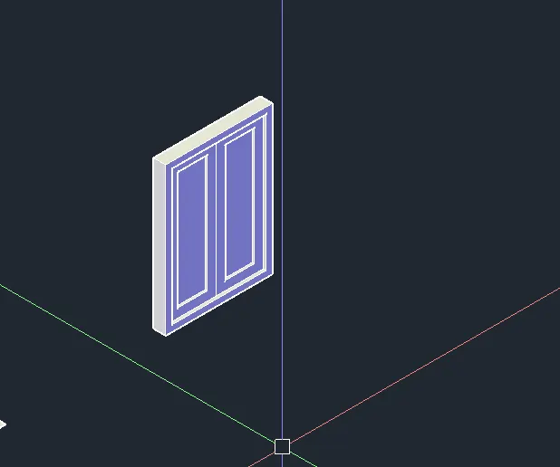
- Use the same procedure to create 3'X4' window.
- Extrude the wall surface and window surface at a height of 8'8''
- Create a rectangle of size 3'X4'2'' at the surface of the wall.
- Make it as a surface by using region command.
- Use 'Presspull' tool, pull the surface and make a cutout.
- Use 'Align' tool, align the 3'X4'2'' window at the cutout.
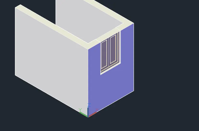
- Use 'Presspull' toll to pull the wall and window at a height of 9'11''
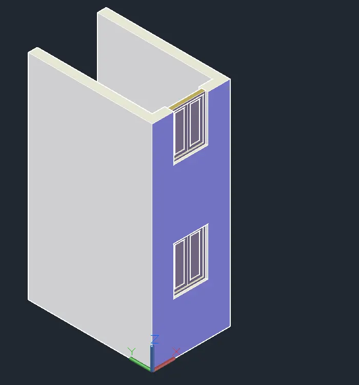
- Use 'Slice' tool, slice the created elevation.
- Use XY plane option.
- Select the lintel level of the window is the axis line.
- The slice is made.
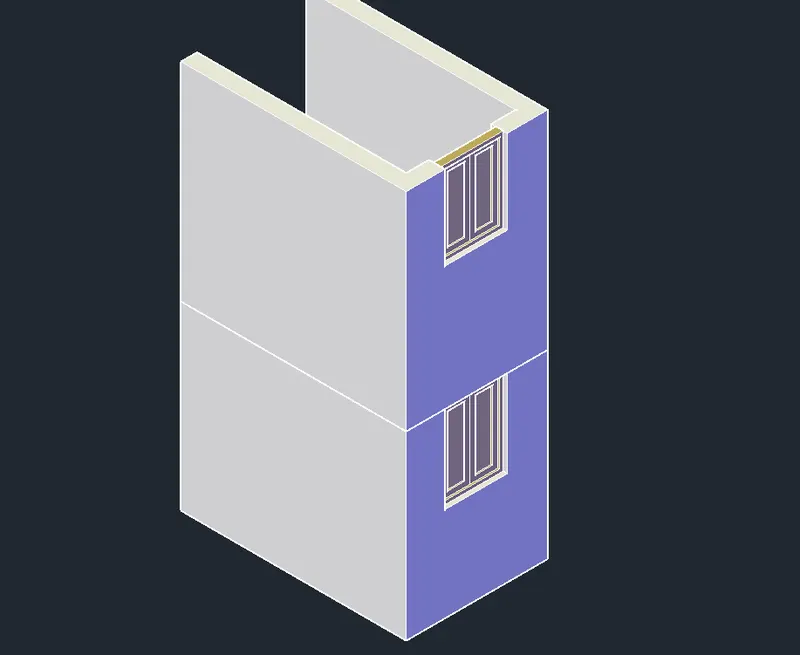
- Use copy tool select the upper part of the object.
- Select the base point at the botttom.
- Paste it to the upper parts to meke another 2 floors.
- Use 'presspull' tool, pull the wall and window at a height of 2'5''
- Use 'Union' tool select the wall solids and make it union.
- Change the UCS to the top of the building.
- Switch to plan view.
- Create a rectangle of size 4''X9'' at the top by specify the first point as the orgin.
- Copy it to the other corner point.
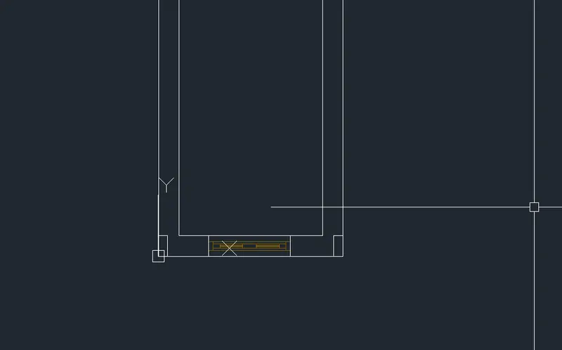
- Create region to the rectangle and meke it as a surface.
- Extrude the rectangle at a height of 6'5''
- Change teh UCS to the face of the rectangle extruded.
- Create a rectangle of size 9''X4'' at the face of the rectangle extruded.
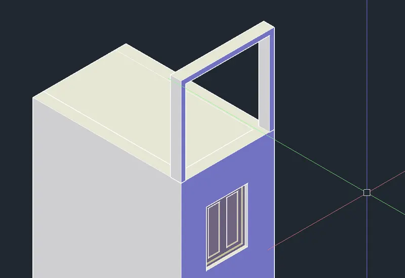
- Use union option to make the created column and beam like structure as a single object.
Result:
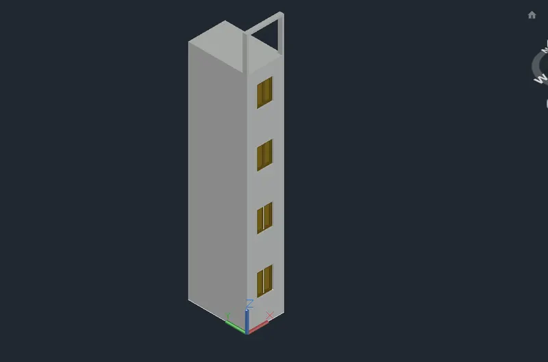
The 3D view of the building facade is created by the given plan and elevation.
Aim:
To create the isometric view of a stair with railing as shown in the plan and elevation.
Introduction:
The 3D view of the stair with railing is created by create a face of the stair in plan and rotate it and extrude it. The rise of the stair is 6'' and thread is 1'. Assume the size of the balustrades is 3' height and 1'' radius. Assume the size of hand rails is 1'' radius. Commonly used commands are line, copy, 3D rotate, region and extrude.
Procedure:
- Open Autocad software in metric units.
- Set the units as engineering and precision as 0'0''
- Change the workspace to 3D modeling.
- Use 'plan' command set the plan view.
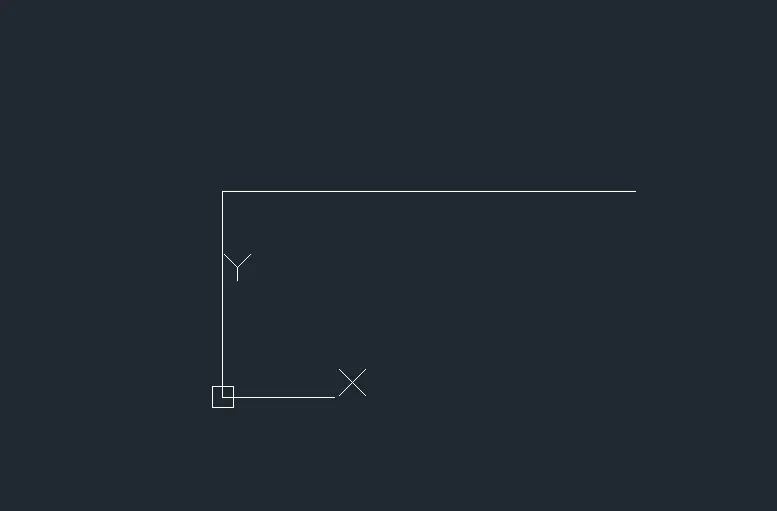
- Create a line by specify the first point as 0,0 and next point @0,6 and @1',0
- Copy the created thread into 9 numbers and extend the last thread at a distance of 2' to make the landing.
- Create a waist slab.
- Create line at a first point as first corner of the thread and second point at the last thread.
- Offset the line at a distance of 6''
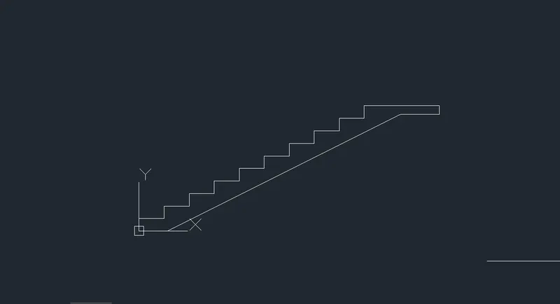
- Change the visual style to South-West isometric.
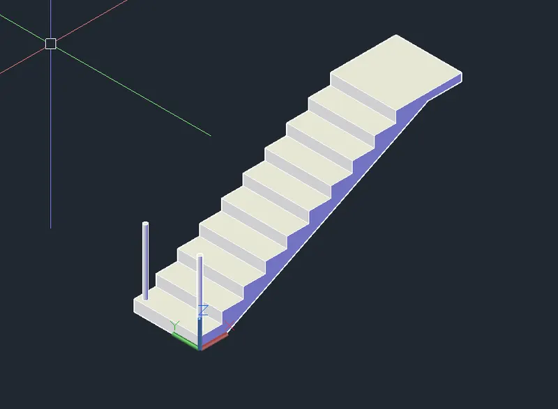
- Use '3D rotate' tool, rotate the object with X-axis as a reference axis at an angle of 90 deg.
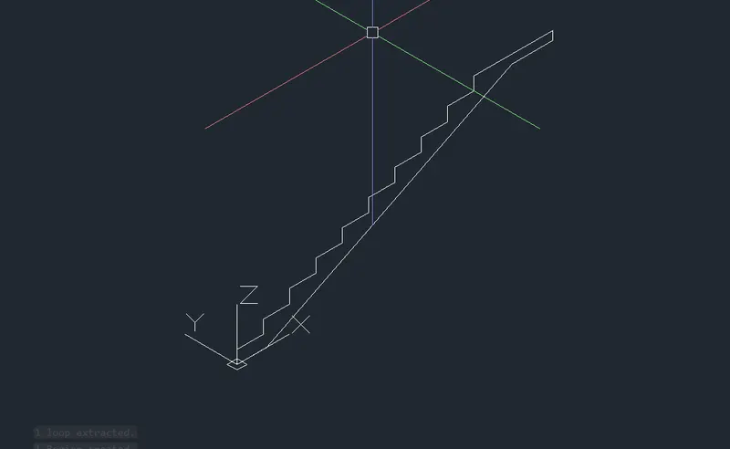
- Use 'Region' command to create the entire object as a surface.
- Use 'Extrude' command.
- Extrude the surface at a distance of 3' in the Y-axis.
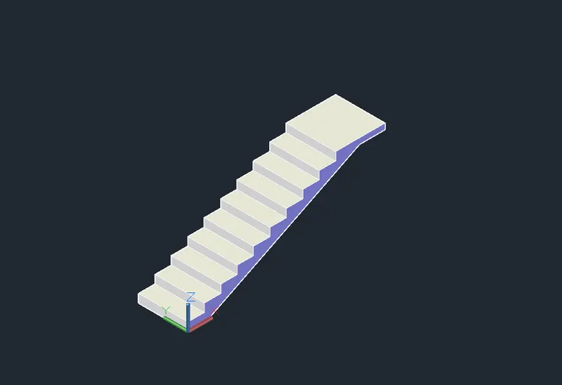
- Change the UCS at the top of the first thread.
- Change the view to plan.
- Create a circle by specify the center point as 3,3 and enter the radius as 1''
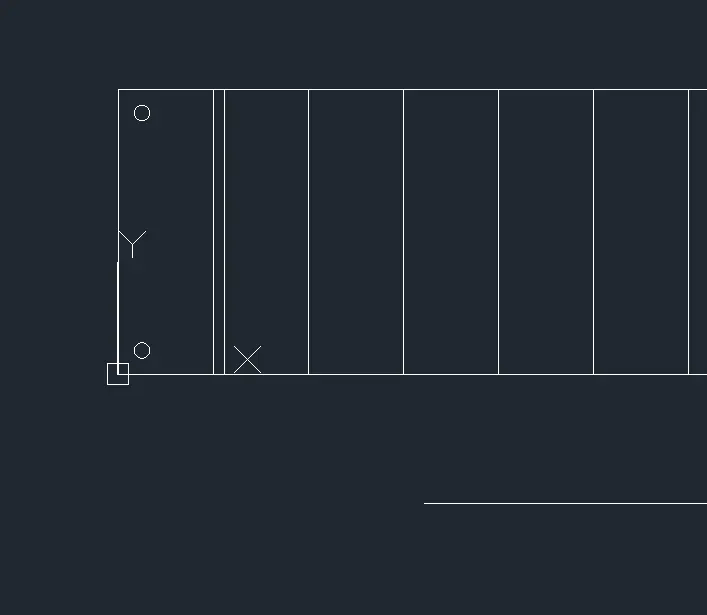
- Change the view to South-West isometric.
- Make region of the circle to make it surface.
- Extrude it at a height of 3'
- Copy the cylinder to the other threads.
- Select the base point as first corner of the thread.
- Create line at the mid of the balustrades and second point at last point of the balustrade.
- Change the UCS at the face of the rail.
- Create circle of radius 1''
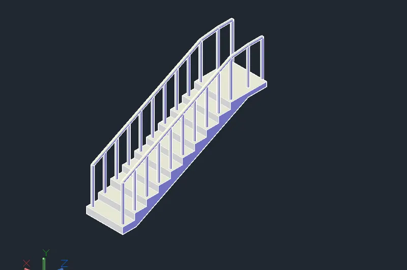
- Use 'Sweep' tool, select the object as circle and the path is the line created.
- Copy the sweeped object to the other side.
Result:
The isometric view of stair with railing is created by the plan and elevation.
Aim:
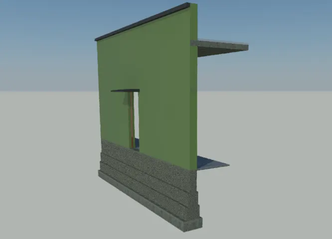
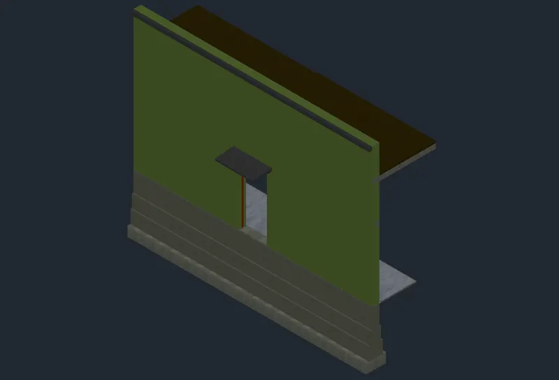
To create the 3D view of a wall with spread footing and create a rendered view of the model with materials.
Introduction:
The 3D view of a wall by creating the plan and extrude it. The length of the wall is 7500mm. door opening is 900mm. Assumed size of parapet wall and choping is 900mm and 150mm. create a camera and place it and render it. Most commonly used commands are line, rectangle, region, extrude, presspull and align.
Procedure:
- Open Autocad file in metric units.
- Set the units as decimal and precision as 0
- Set the view as plan by typing 'plan' in the command prompt.
- Create a tectangle of size 230mmX7500mm
- Explode it.
- Offset the base line at a distance of 3300mm and 900mm, create a door opening.
- Create the frame of the door by using rectangle tool.
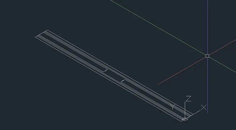
- Offset the wall line at a distance of 50mm,50mm and 100mm respectively both the sides of the wall.
- Change the view to South-West isometric.
- Create surface to the walls by using 'planar' tool under the surface tab.
- Extrude the wall at a distance of 3300mm.
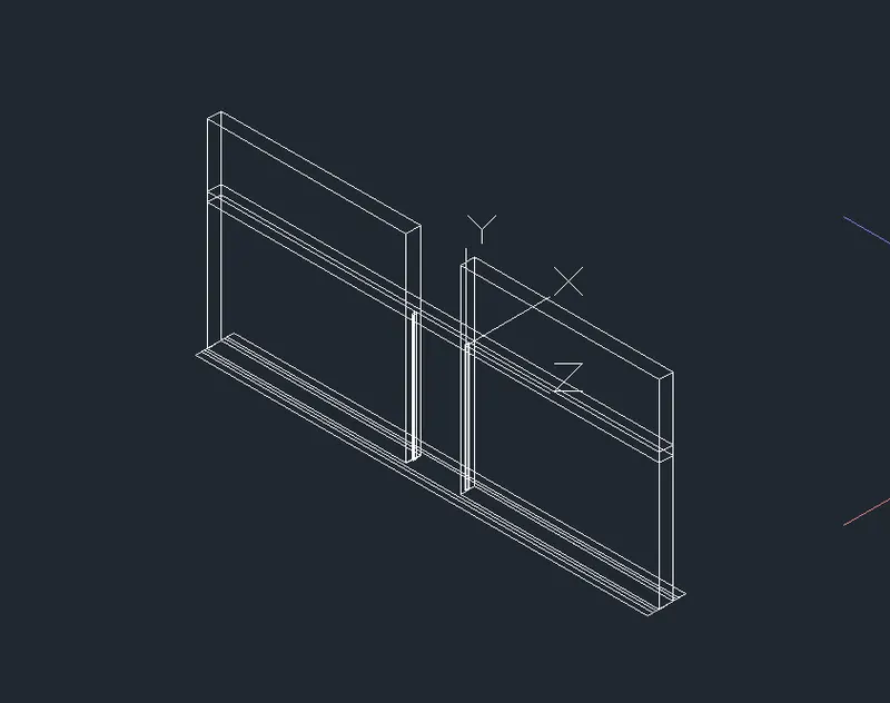
- Extrude the door frames at a distance of 2100mm.
- Change the UCS to the upper side of door frame and create rectangle of size 230X150mm.
- Extrude the rectangle throughout the wall.
- Create sunshade by set the view as plan.
- By using line create the profile of the sunshade.
- Use '3Drotate' command, rotate the object 90 deg with respect to X-axis.
- Make it as a surface and extrude it at a distance of 900mm.
- Copy and place it at the lintel above door.
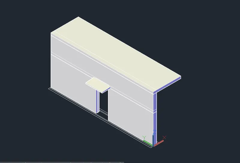
- Create a slab.
- Create a rectangle at the top of the wall face of size 230X7500mm.
- Extrude it at a height of 150mm.
- Use presspull, pull the slab to some distance.
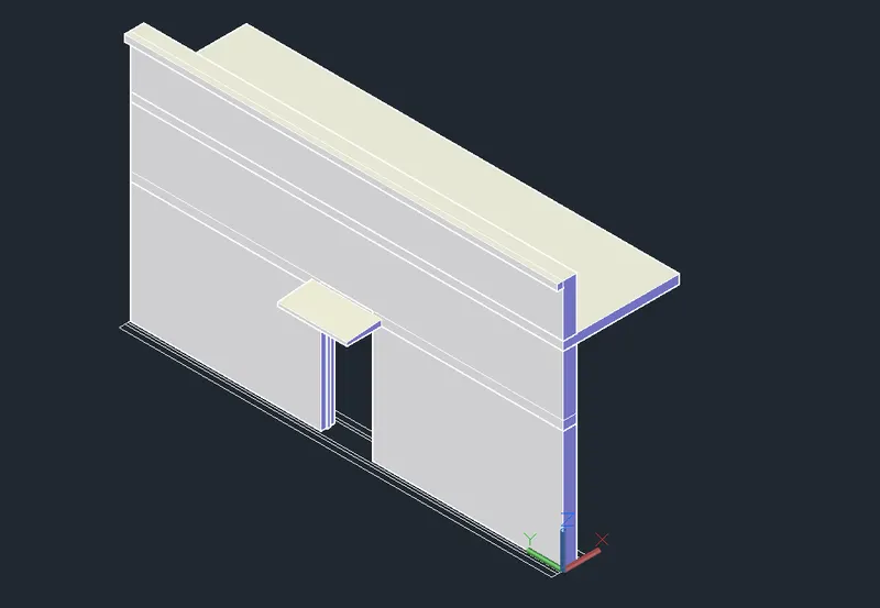
- Create parapet wall.
- Create rectangle of size 230X7500mm at the top of the slab.
- Make it a surface and extrude it at a height of 900mm.
- Create choping.
- Create rectangle at the face of the parapet wall of size Thickness is 100mm and width is 150mm.
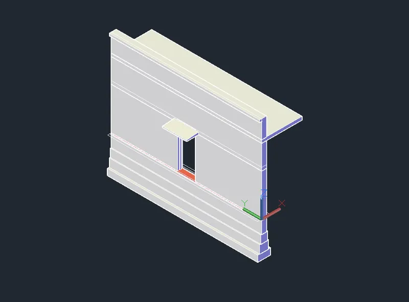
- Create DPC of size 230X50mm at the bottom of the wall.
- Set the view as 2D wireframe.
- Switch the view cube to bottom South-West isometric.
- Use planar Create the surface to the footing.
- Extrude the first step of footing at a depth of 600mm.
- Follow the same procedure to create the other two steps of footing.
- Second footing at a depth of 400mm and third footing at a depth of 400mm.
- Create PCC by following the same procedure at a depth of 300mm.
- Switch the view to South-West isometric.
- Assign materials to the model.
- Open the material browser under the visualize tab.
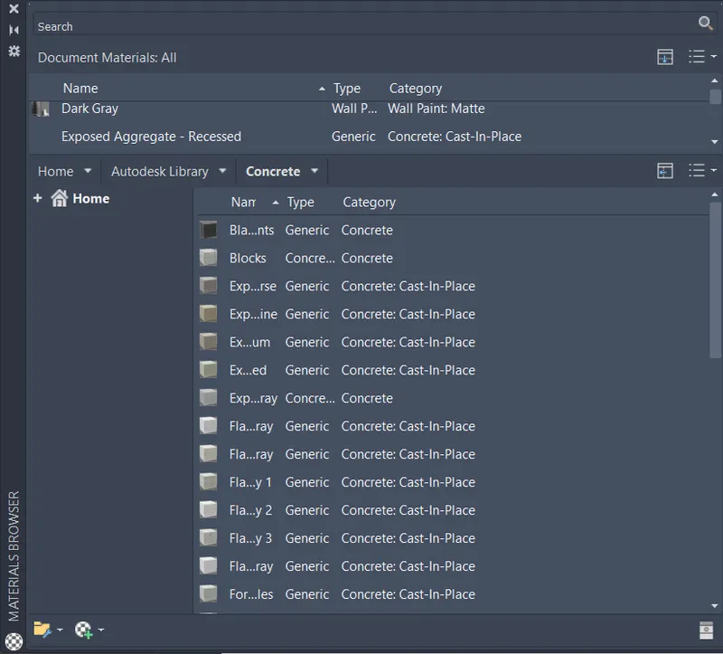
- Select wall painting.
- Select olive green and assign it to the walls.
- Select concrete and assign it to the slabs and footing.
- Select wood and assign it to the door frame.
- Select marble and assign it to the floor.
- Select stone finish and assign it to the terrace foor.
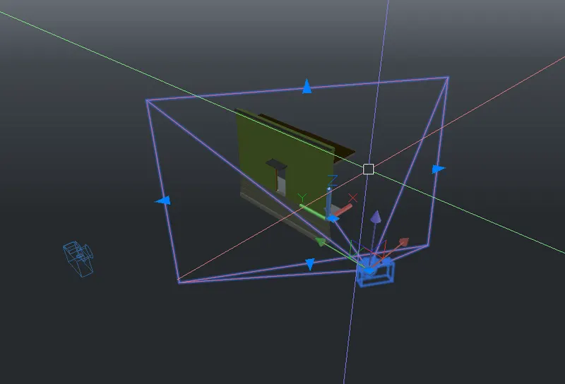
- Create a camera.
- Select 'Create new camera' under visualize tab.
- Place the camera in the workspace focus to the model.
- Select the new view.
- Save the view as cmera 1.
- Turn on the syk background under the visualize tab.
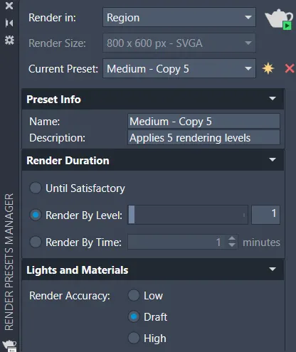
- Type 'RR' in the command prompt.
- Set the render details as shown in the below figure.
- Click the render icon, render the model.
- After render save it as 'jpeg' format.
Result:
The 3D view of a wall with spread footing is created and the rendered view of the model with materials is rendered and created.