Creating 3D Isometric view of various structural elements in AutoCAD
1.ANS
AIM: to Creating a 3D Isometric View of the building with plan and elevation given.
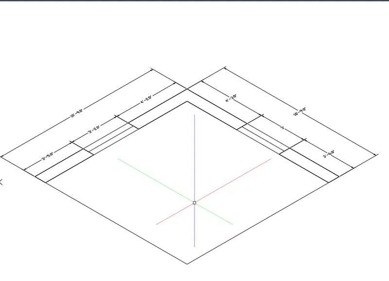
PLAN
PROCEDURE:
1. select the rectangle and draw the 10'9"x10'9"
2.select the offset and 9"
3.select the command explode and select the object enter
4.select the offset and draw the windows are 3'2" and 3'
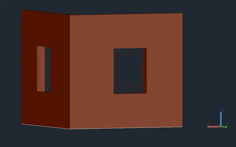
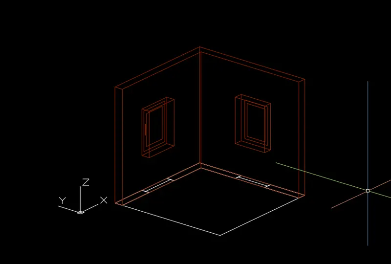
1.select the boundary region and select the object
2.select the extrude and height is 10'
3.select the rectangle and draw the window
4.select the window and move the sill level at 3'
5.next select the rectangle and extrude at height is 4'
3. ANS
AIM: Creating the isometric 3d view of a stair with railing as shown in the plan and elevation. Assume the size of the balustrades and the hand rails.
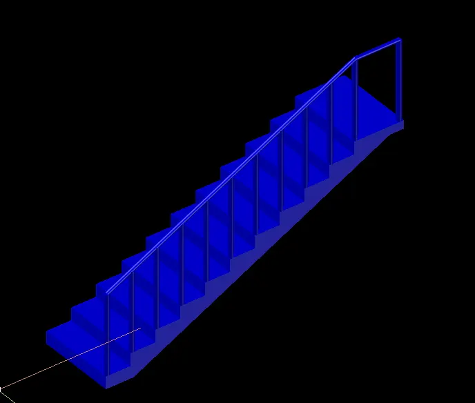
select the top view first and select the line command draw the rise and tread
is 6" rise and 1' is tread
select the object and copy up to 9 steps and extend the last one is landing 2' extra here
select the view cube in wcs and rotate the object in x axis is 90 degrees
select the boundary next extrude the object
select the circle and draw the rail height extrude is 3'2" and copy the rail and place each step
select the line and connect the all rails and select the circle and draw
select the sweep and select the circle and path line enter
2.ANS
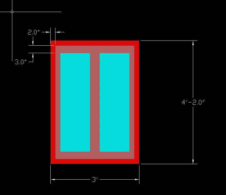
AIM: Creating the 3D View of the Building Façade as given in the plan and elevation. Also, see the detail of the window.
WINDOW DETAILS
select the rectangle and draw given dimensions and offset is 2"
select the line and draw at offset line middle
select the object and explode and offset 3" is given and trimmed the extra lines
3D BUILDING VIEW of the building
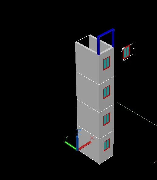
select the rectangle and draw the dimensions are 6'9"x10'9"
offset 9"
explode the offset line and trimmed the extra lines
create the region and extrude the wall
select the line draw the 6'5"height and width is 6'5"
select the rectangle and dimensions 4"x9"
select the sweep and object select and path is given by the line and copy the object ,place the top of building
4.ANS
AIM: Create the 3D view of a Wall with spread footing
PROCEDURE:
open AutoCAD and set the limits and units
select the line command draw the as shown in figure
select the region and create
select extrude the selected object is 10000mm
create the layers like wall, footing, parapet wall, stepped footing etc...
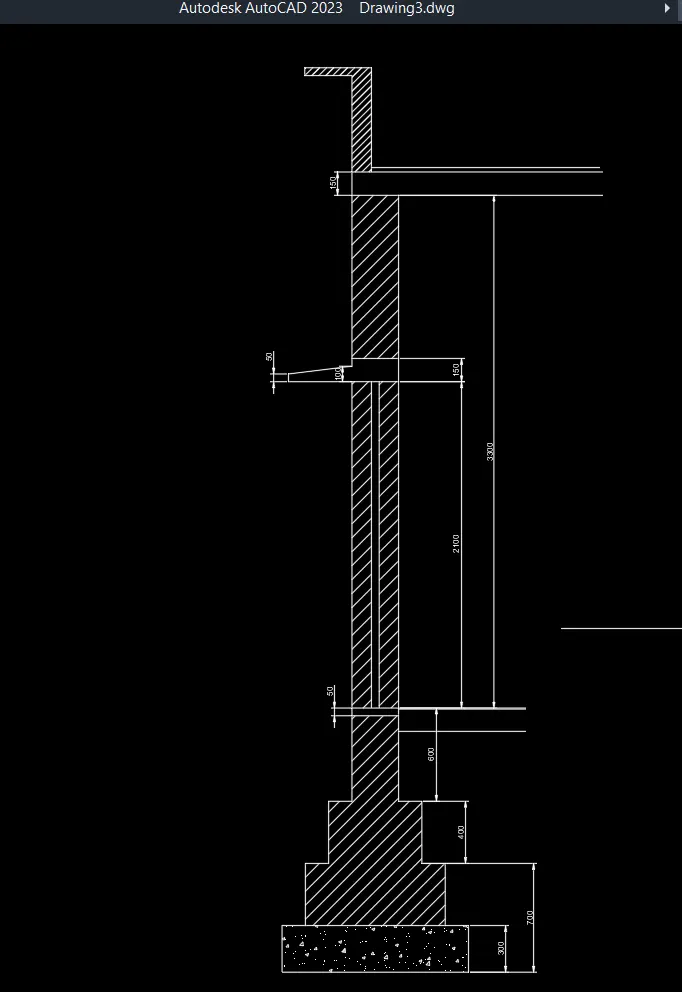
SECTION-VIEW
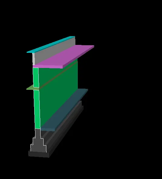
camera view
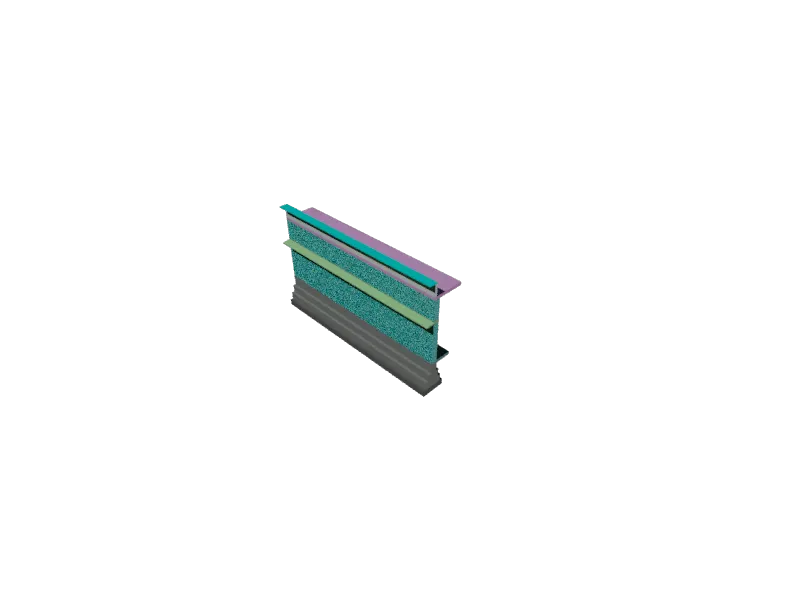
select the camera and set the location and target
assign the materials of material browsing given the wall paint footing etc...
next the rendering
save the rendering image