Creating 3D Isometric view of various structural elements in AutoCAD
TASK 1:
AIM:
To create a 3D Isometric View of the building with plan and elevation given.
PROCEDURE:
- Go to START MENU, select AutoCAD 2023
- Click on START DRAWING .DWG File
- In the Command line type in: STARTUP [ENTER]
- Enter new value of startup: 1
- Go to Application Menu and select New
- Next select the 'Engineering' unit system from the 'Advanced Setup' option.
- Set the Units to "mm" by using the command 'un'.
- Set the limits by entering LIMITS in the Command tab. The lower-left corner is specified as 0,0, and the upper-right corner is specified as 100,100.
Commands used:
- Line command,
- Dimlinear command,
- Text command,
- Offset,
- Trim,
- Extend.
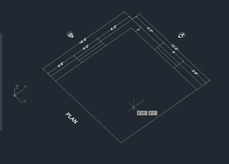
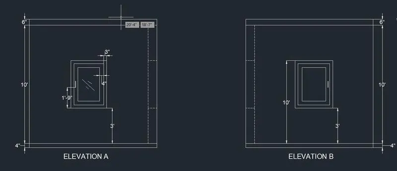
TASK 2:
AIM:
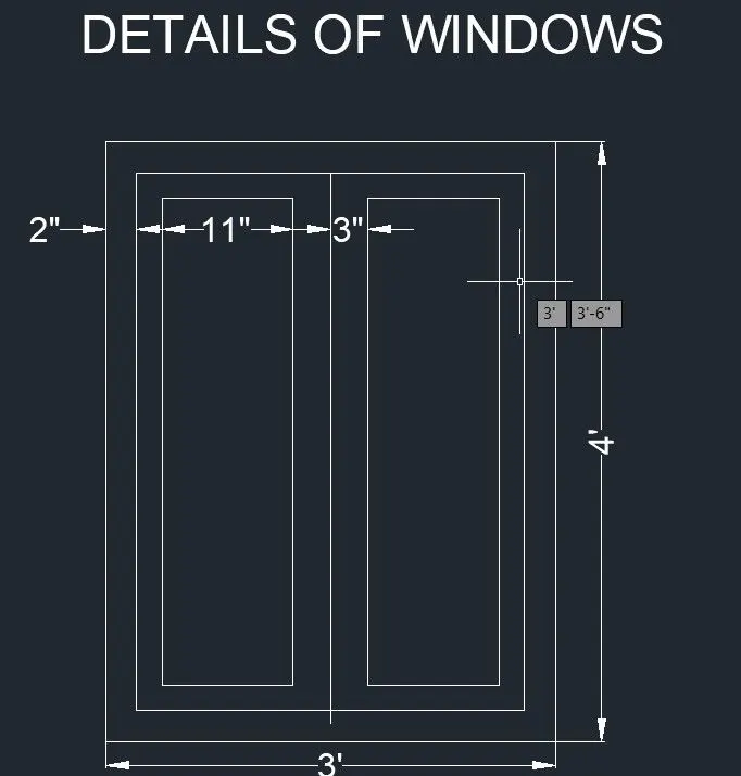
To create the 3D View of the Building Façade as given in the plan and elevation. Also, see the detail of the window.
PROCEDURE:
- Go to START MENU, select AutoCAD 2023
- Click on START DRAWING .DWG File
- In the Command line type in: STARTUP [ENTER]
- Enter new value of startup: 1
- Go to Application Menu and select New
- Next select the 'Engineering' unit system from the 'Advanced Setup' option.
- Set the Units to "mm" by using the command 'un'.
- Set the limits by entering LIMITS in the Command tab. The lower-left corner is specified as 0,0, and the upper-right corner is specified as 100,100.
Commands used:
- Line command,
- Dimlinear command,
- Text command,
- Offset,
- Trim,
- Extend.
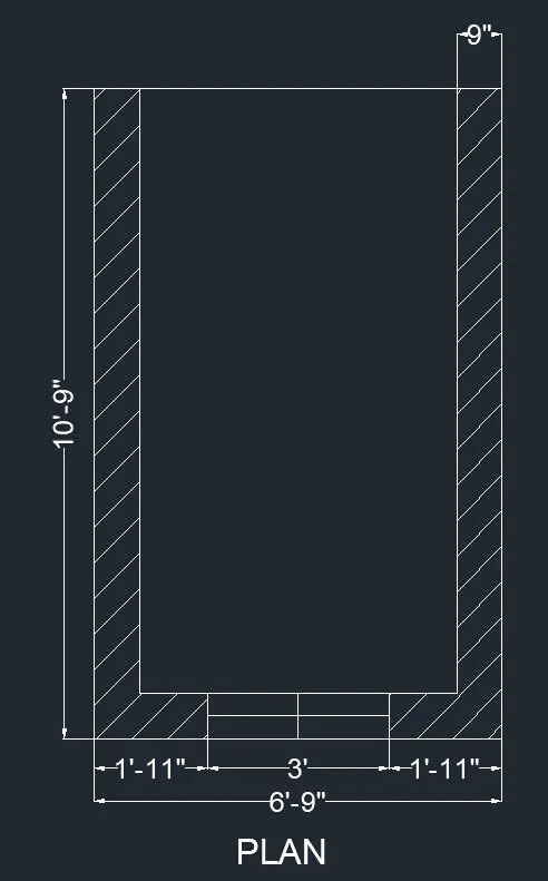
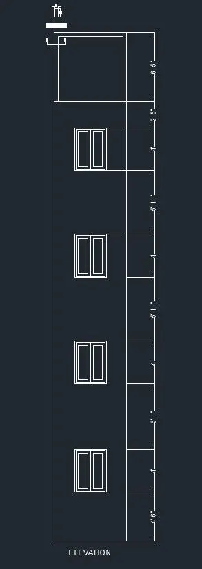
TASK 3:
AIM:
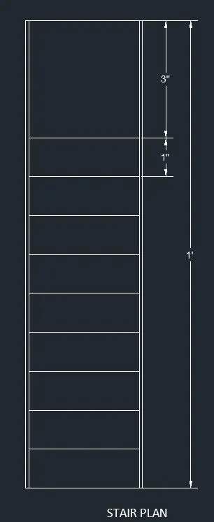
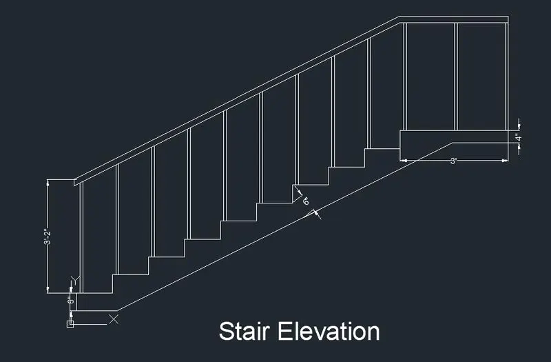
To create the ismoteric 3d view of a stair with railing as shown in the plan and elevation. Assume the size of the balustrades and the hand rails.
PROCEDURE:
- Go to START MENU, select AutoCAD 2023
- Click on START DRAWING .DWG File
- In the Command line type in: STARTUP [ENTER]
- Enter new value of startup: 1
- Go to Application Menu and select New
- Next select the 'Engineering' unit system from the 'Advanced Setup' option.
- Set the Units to "mm" by using the command 'un'.
- Set the limits by entering LIMITS in the Command tab. The lower-left corner is specified as 0,0, and the upper-right corner is specified as 100,100.
Commands used:
- Line command,
- Dimlinear command,
- Text command,
- Offset,
- Trim,
- Extend.
TASK 4:
AIM:
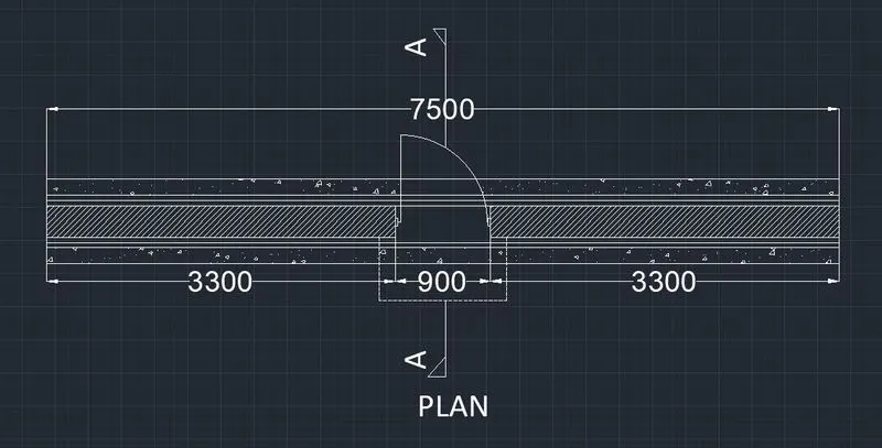
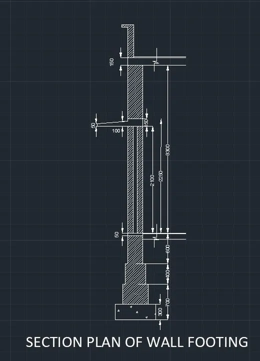
To create the 3D view of a Wall with spread footing . Create the Door opening only. Assume the size of the parpaet and the coping. See the plans and elevation for the details. Also, create a rendered view of the model with materials as of your choice.
PROCEDURE:
- Go to START MENU, select AutoCAD 2023
- Click on START DRAWING .DWG File
- In the Command line type in: STARTUP [ENTER]
- Enter new value of startup: 1
- Go to Application Menu and select New
- Next select the 'Engineering' unit system from the 'Advanced Setup' option.
- Set the Units to "mm" by using the command 'un'.
- Set the limits by entering LIMITS in the Command tab. The lower-left corner is specified as 0,0, and the upper-right corner is specified as 100,100.
Commands used:
- Line command,
- Dimlinear command,
- Text command,
- Offset,
- Trim,
- Extend.
Thus the Challenge is Completed.