Creating 3D Isometric view of various structural elements in AutoCAD
07/07/21
Answer
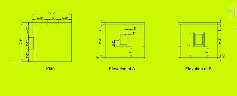
1. Create a 3D Isometric View of the building with plan and elevation given.
Aim
Create a 3D Isometric View of the building with plan and elevation using Autocad.
Procedure
STEP-1 opening to the AutoCAD software and entering the workspace.
STEP-2 Setting limits >specify lower-left corner:0,0
STEP-3 specify upper-left corner:100,100
STEP-4 Set>units>Demical>intersectional scale>mm
STEP-5 Limmax>100,100
STEP-6 makes the 2-D plan as per the given requirements.
STEP-7use the extrude command> to create the 3-D wall for the surrounding.
STEP-8 subtract command> boolean command helps as to cut the hole on the object
STEP-9 box command> helps to make the window in the defined format.
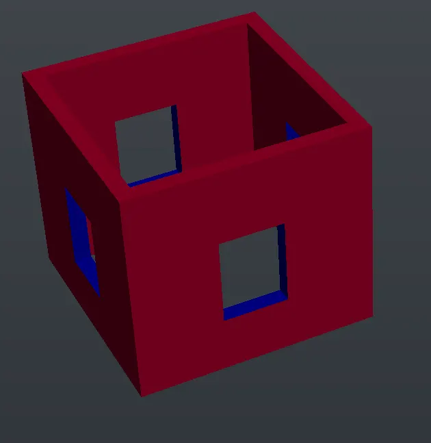
STEP-10 3Dface command> helps to make the surface of the object.
STEP-11 3Dorbit command> helps to rotate the view in our format.
STEP-12 render command > help to render the object in the 3-D form.
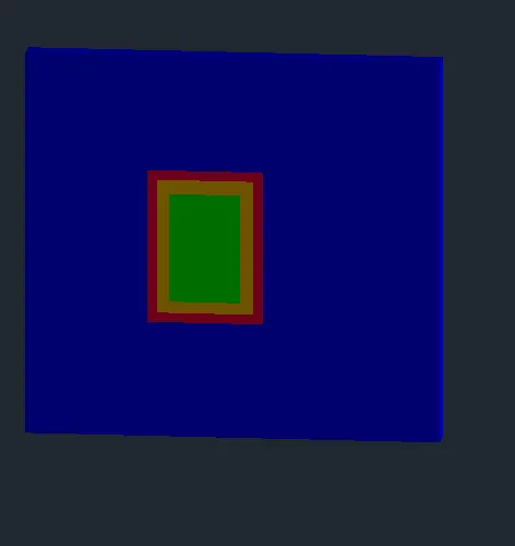
STEP-13 Material command> helps to apply the materials to the selected object.
STEP-14 Cylinder command> help to Create the cylindrical shape in the Format.
STEP-15 3Drotate command> help to rotate in the different plane.
STEP-16 close the entire object
STEP-17 and save the file for feature use.
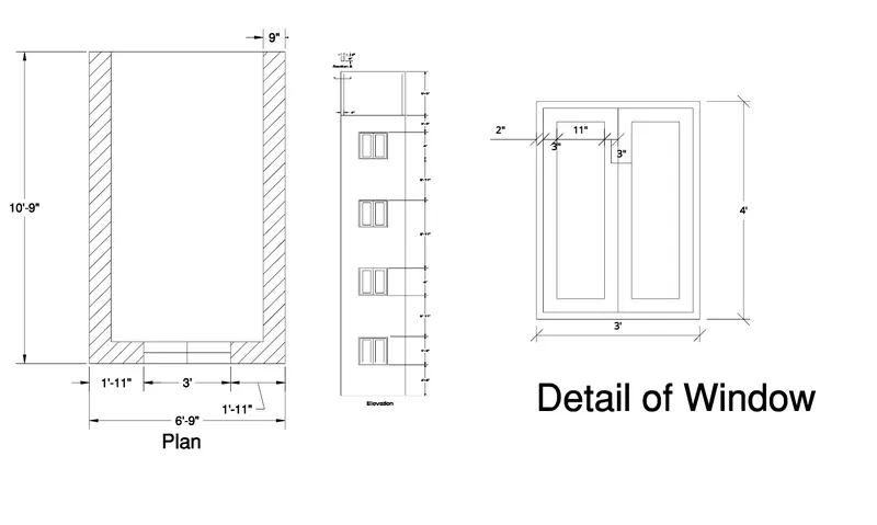
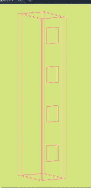
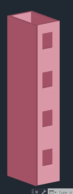
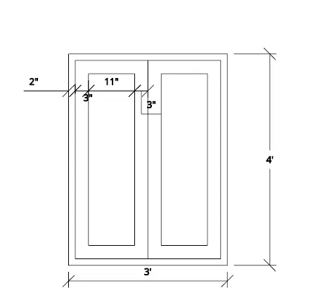
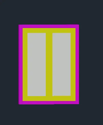
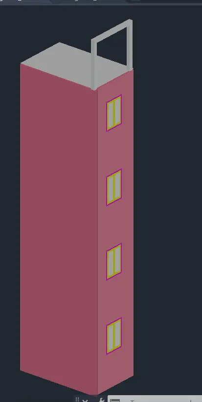
2. Create the 3D View of the Building Façade as given in the plan and elevation. Also, see the detail of the window.
Aim
Create the 3D View of the Building Façade as given in the plan and elevation using Autocad.
Procedure
STEP-1 opening to the AutoCAD software and entering the workspace.
STEP-2 Setting limits >specify lower-left corner:0,0
STEP-3 specify upper-left corner:100,100
STEP-4 Set>units>Demical>intersectional scale>mm
STEP-5 Limmax>100,100
STEP-6 makes the 2-D plan as per the given requirements.
Shaded View
STEP-7use the extrude command> to create the 3-D wall for the surrounding.
STEP-8 subtract command> boolean command helps as to cut the hole on the object
STEP-9 box command> helps to make the window in the defined format.
STEP-10 3Dface command> helps to make the surface of the object.
Window Details
STEP-11 3Dorbit command> helps to rotate the view in our format.
STEP-12 render command > help to render the object in the 3-D form.
STEP-13 Material command> helps to apply the materials to the selected object.
STEP-14 Cylinder command> help to Create the cylindrical shape in the Format.
STEP-15 3Drotate command> help to rotate in the different plane.
STEP-16 close the entire object
STEP-17 and save the file for feature use.
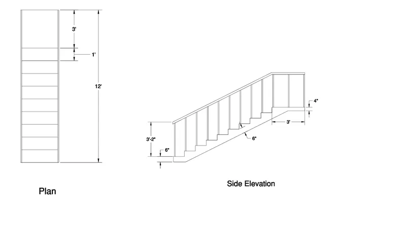
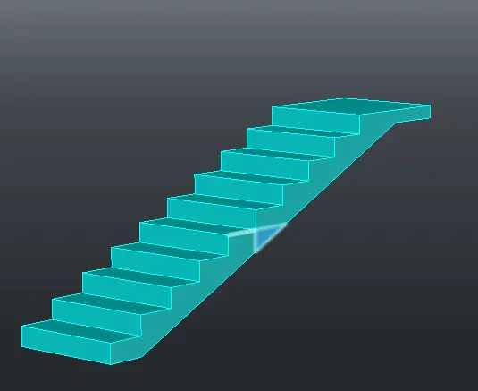
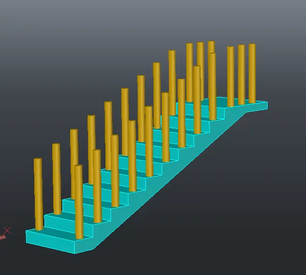
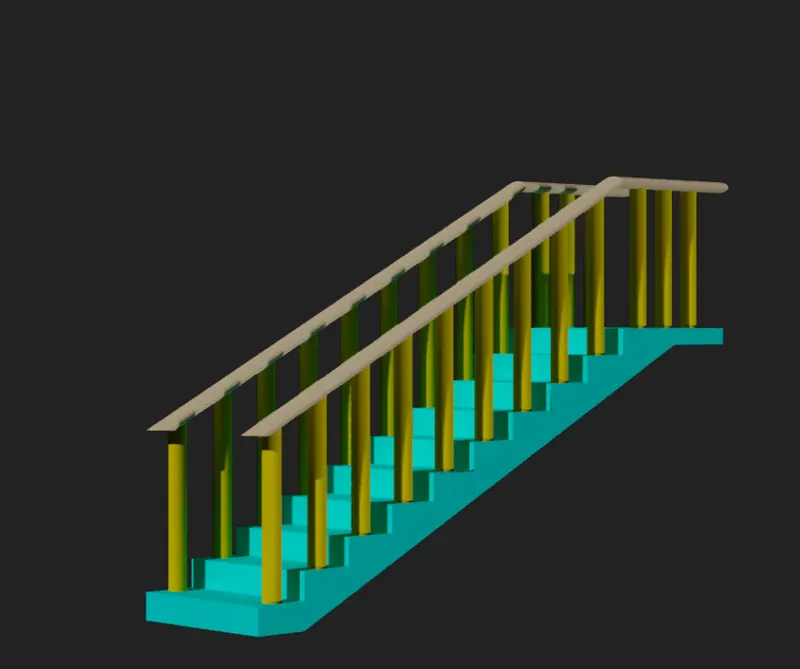
3. Create the isometric 3d view of a stair with a railing as shown in the plan and elevation. Assume the size of the balustrades and the handrails.
Aim
Create the isometric 3d view of a stair with a railing using Autocad.
Procedure
STEP-1 opening to the AutoCAD software and entering the workspace.
STEP-2 Setting limits >specify lower-left corner:0,0
STEP-3 specify upper-left corner:100,100
STEP-4 Set>units>Demical>intersectional scale>mm
STEP-5 Limmax>100,100
STEP-6 makes the 2-D plan as per the given requirements.
STEP-7use the extrude command> to create the 3-D wall for the surrounding.
STEP-8 subtract command> boolean command helps as to cut the hole on the object
STEP-9 box command> helps to make the window in the defined format.
STEP-10 3Dface command> helps to make the surface of the object.
STEP-11 3Dorbit command> helps to rotate the view in our format.
STEP-12 render command > help to render the object in the 3-D form.
STEP-13 Material command> helps to apply the materials to the selected object.
STEP-14 Cylinder command> help to Create the cylindrical shape in the Format.
STEP-15 3Drotate command> help to rotate in the different plane.
STEP-16 close the entire object
STEP-17 and save the file for feature use.
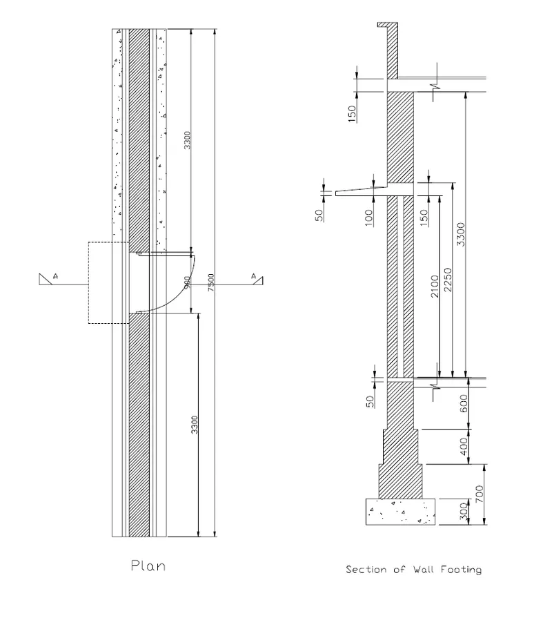
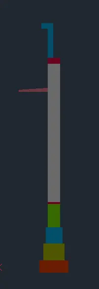
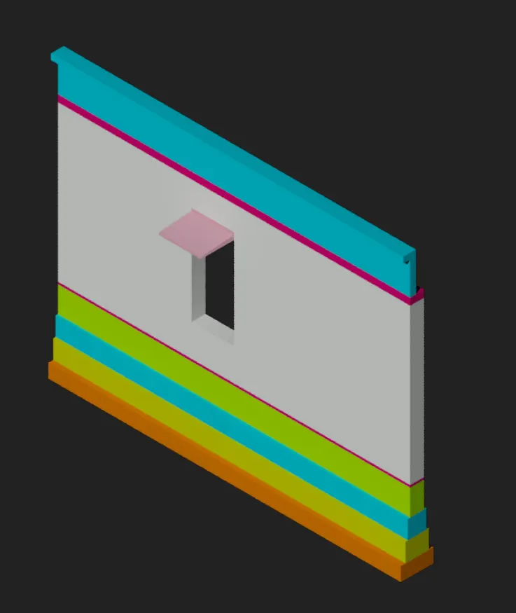
4. Create the 3D view of a Wall with spread footing. Create the Door opening only.
Aim
Create the 3D view of a Wall with spread footing using Autocad.
Procedure
STEP-1 opening to the AutoCAD software and entering the workspace.
STEP-2 Setting limits >specify lower-left corner:0,0
STEP-3 specify upper-left corner:100,100
STEP-4 Set>units>Demical>intersectional scale>mm
STEP-5 Limmax>100,100
STEP-6 makes the 2-D plan as per the given requirements.
STEP-7use the extrude command> to create the 3-D wall for the surrounding.
STEP-8 subtract command> boolean command helps as to cut the hole on the object
STEP-9 box command> helps to make the window in the defined format.
STEP-10 3Dface command> helps to make the surface of the object.
STEP-11 3Dorbit command> helps to rotate the view in our format.
STEP-12 render command > help to render the object in the 3-D form.
STEP-13 Material command> helps to apply the materials to the selected object.
STEP-14 Cylinder command> help to Create the cylindrical shape in the Format.
STEP-15 3Drotate command> help to rotate in the different plane.
STEP-16 close the entire object
STEP-17 and save the file for feature use.